independence, programming languages, implementation techniques. CR CATEGORIES: ... posed as a base for implementing a mobile programming system.
Programming Techniques
The Mobile Programming System: STAGE2 W. iVL WAITE
University of Colorado,* Boulder, Colorado STAGE2 is the second level of a bootstrap sequence which is easily implemented on any computer. It is a flexible, powerful macro processor designed specifically as a tool for constructing machine-independent software. In this paper the features provided by STAGE2 are summarized, and the implementation techniques which have made it possible to have STAGE2 running on a new machine with less than one man-week of effort are discussed. The approach has been successful on over 15 machines of widely varying characteristics. KEY WORDS AND PHRASES. bootstrapping, macro processing, machine
independence, programming languages, implementation techniques CR CATEGORIES: 4.12, 4.22
1.
Introduction
In an earlier paper [1] R. J. Orgass and I presented a trivial macro processor called SIMCMP, which we proposed as a base for implementing a mobile programming system. The design criterion for SIMCMP was simplicity of implementation, and it was severely limited in the source code which it could accept. Its sole function was to translate a more complex processor. This paper describes STAGE2, the second level of the bootstrap. STAGE2 is a flexible, powerful macro processor written in a language which can be translated by SIMCMP. It is designed specifically for the task of implementing machine-independent software, although it can also serve other purposes. Some features normally associated with a generalized macro processor have been omitted (for example, all macro definitions must be presented before any source code is read). These omissions are required because of restrictions imposed by SIMCMP on the number of program labels. They do not affect the primary function of STAGE2, and hence I feel that they do not represent design flaws. To be effective as a tool for creating machine-independent software, STAGE2 itself must be highly mobile. For this reason, the support which the system requires from existing software on the target computer should be * Department of Electrical Engineering Volume 13 / Number 7 / July, 1970
R. MORRIS, Editor
minimal. A generalized I/O package [2] provides the I/O interface for both SIMC1VIP and STAGE2. It assumes that the following operations on sequential files are provided by the operating system available on the target machine: (1) read one line, (2) detect end-of-file, (3) write one line, (4) write end-of-file, (5) rewind. These operations need only be available on those devices for which they are meaningful. The generalized I/O package carries flags which specify the legal operation on each device and will intercept any illegal requests. In a minimal configuration, only three devices are required by STAGE2. Conceptually, they are a "card reader," "card punch," and "printer," but they may be implemented by any physical devices. It must be possible to perform operations (1) and (2) on the "card reader," and operation (3) on the "card punch" and "printer." Operation (4) can be used to clear the last buffer if the output is blocked. As described in Section 2, STAGE2 can use secondary storage (tape or disk) to advantage. A total of nine files, including the three just mentioned, would be the maximum. The six additional files can be used as secondary storage devices, additional inputs, or additional outputs. Generally all five operations would be possible on each, although this is not strictly necessary. Implementation of STAGE2 on a new computer requires less than one man-week of effort. An existing version is unnecessary; the bootstrap process is carried out from a source deck, tape, or listing. The system has been tested in over 15 implementations, several completed by inexperienced personnel. The basic design philosophy of the system [3, 4] indicates a possible solution to the "software crisis" which is plaguing the computer industry today. The remainder of this paper gives a brief overview of the facilities provided by STAGE2, and the programming techniques used in its construction. A comprehensive user's manual [5] is available for those interested in further details. 2.
User's View
In many ways, STAGE2 is similar to LiMP [6]. It employs a scanning mechanism to recognize macro calls and isolate parameter strings, and the ability to perform different parameter conversions has been retained and extended. The code body does not include the "grouping" concept, nor LIMP'S SNOBOL interpreter. Free use of I/O devices is permitted. Each macro definition has two parts: a template and a code body. The template is used as a pattern for recognition of macro calls, and the code body directs the expansion of the macro. Both the template and the code body Communications of the ACM
415
use special characters which are specified on the first line of the definitions (the flag line). Table I summarizes these characters. Template matching is carried out by a scanner which compares the input line with the templates. Characters in the template which are not parameter flags (Table I) must match the corresponding characters of the input line exactly. A parameter flag will match any substring of the input line which is balanced with respect to the parentheses specified by the flag line (a null string is considered to be balanced). B y requiring that a parameter flag match a balanced substring of the input line, STAGE2 allows grouping b y parentheses. This is a useful feature when structures such as arithmetic expressions or lists of operands are being analyzed.
ALPHA = (BETA + GAMMA) • DELTA (a) A typical input line ALPHA = (') * DELTA ALPHA = ' . ' ALPHA
,
=
=
'
(').,
(b) Several templates which could match the input line given in Figure l(a) FIG. 1. Template matching
Figures l(a) and l(b) show an input line and several templates which would match it. The flag characters are those of Table I. Ambiguity in the template match is resolved by five rules (see Appendix). Together they have the effect of maximizing the number of literal characters matched. In Figure 1, for example, the rules force the input fine to match the first template. The actual parameters of a macro call are the substrings which match the parameter flags of the template. Within the code body, these actual parameters are referred to by number: the string matched to the leftmost flag is parameter 1, the one matched to the next flag is parameter 2, and so forth. A maximum of nine flags is allowed in a single template. The first template of Figure l(b) has a single parameter flag. If the input line of Figure l(a) were matched to this template, actual parameter 1 would be B E T A + GAMMA. Actual parameters 2-9 would not be defined by the template match. Associated with each template is a code body which specifies the text to be constructed by the macro. Each line of the code body is used to construct a line which is then either output (by means of a processor function, see 416
Communications of the ACM
TABLE Character Position
1 2 3 4 5 6 7 8 9 10 11 12
I.
CHARACTERS DEFINED BY THE FLAG LINE Meaning
End of source language line Parameter flag for template End of target language line Escape character for target language Zero Filler for fixed fields in the target language Left parenthesis Addition operator Subtraction operator Multiplication operator Division operator Right parenthesis
Character
$ # 0 space ( -+ * / )
(3) below) or else is resubmitted to the scanner for recognition. To construct the line, characters are copied from the code body line until the end-of-line (Table I) is recognized. The line is then terminated and passed to the scanner. If an escape character (Table I) is recognized during this process, it is not copied, and the next character of the line is examined to determine what action should be taken. There are three possibilities: (1) If the next character is an escape or an end-of-line, then it is copied into the line being constructed. (2) If the next character is a digit, then some transformation of the corresponding actual parameter is copied into the line being constructed. The particular transformation applied is determined by the character following the digit (see Table II). A transformation applied to parameter 0 is interpreted as a request for an arbitrary symbol which is unique within the current macro. Up to ten such symbols can be generated in any one macro. The second character following the escape specifies which symbol should be copied into the line being constructed. (3) If the next character is F, then a special processor function is executed. The particular function is determined b y the character following the F (see Table III). S T A G E 2 provides three levels of storage: parameters, an associative memory, and up to six I / O files. The parameters can be used for working storage within a single macro. Information can be made accessible to all macros via the associative memory. Intermediate text can be written on any of the I / O files and later recovered. Each macro call has storage space for nine parameters associated with it. The template match may establish initial values for some of these parameters. Parameter values may also be established b y the code body, using transformation 6 (see Table II). The scope of the parameters is the code body of the macro in which they were established. T h e y are not accessible to macros called by the code body. Their values are, however, preserved during such calls. On completion of a call, all parameters associated with that call disappear. Volume 13 / Number 7 / July, 1970
T A B L E II.
PARAMETER CONVERSION DIGITS
Conversion Digit
A cllon
0 1, 2 3 4
Copy the parameter to the constructed line Copy a string from memory to the constructed line Copy the break character to the constructed line Copy the value of a parameter, treated as an arithmetic expression, into the constructed line Copy a parameter length to the constructed line Reset the value of a parameter Initiate a context-controlled iteration Copy an integer equivalent to a single character into the constructed line
5 6 7 8
T A B L E III. Function Digit
7 8 9
E
PROCESSOR FUNCTION DIGITS A c/ion
Terminate processing Output a line without rescanning Change I/O channels and copy text Store information into memory Set skip counter unconditionally Set skip counter conditionally on string equality Set skip counter conditionally on the relative values of two expressions Initiate a count-controlled iteration Advance an iteration Escape from the current macro Generate error traceback
The associative memory is addressed by character strings, and its contents are also character strings. No restriction is placed on the format of either addresses or contents. Information is entered into m e m o r y b y a processor function, and accessed by parameter transformations. Because it is global to all macro calls, the m e m o r y can be used to pass information between macros. Typical uses of the memory are to hold a symbol table, a pushdown stack for translating expressions, and information about the current contents of various registers for use in "peephole" optimization [7]. A m a x i m u m of nine I / O files can be made accessible to STAGE2. At least three (the "reader," " p u n c h , " and "printer") will always be available. By suitable processor functions, the user can direct output generated b y S T A G E 2 to any file on which writing is allowed. The input m a y be switched to any file on which reading is allowed. Any file m a y be rewound if rewinding is allowed by its implementation. The main use of I / O files is to permit multipass operation. For example, complex code optimization, such as register allocation [8, 9], can be performed using the available I / O files for t e m p o r a r y storage of intermediate text. Information about register contents can be accumulated in the memory between labels, while intermediate Volume 13 / Number 7 / July, 1970
text is written on one or more files. At the next label, this information is examined and a register assignment made. The intermediate text is then read back and the final code is generated. S T A G E 2 can evaluate integer arithmetic expressions involving addition, subtraction, multiplication, and division. Parentheses m a y be used to any depth (subject to storage availability). The operands m a y be either explicit integers or symbols. A symbol is looked up in the associative memory, where it must have an integer value. Conditional operations are available for testing the equality of two strings and the relative magnitude of two expressions. I f the condition is satisfied, an expression is evaluated to determine how m a n y lines should be skipped. A skip is not restricted to the macro in which the conditional operation appeared. I t is possible to loop within a code body. The loop is controlled either b y a counter or b y a string and a set of delimiters. Using the latter, known as context controlled iteration, it is possible to analyze complex parameters such as lists of operands and arithmetic expressions. The context controlled iteration is, in effect, a token breakout routine similar to t h a t found in a compiler. No particular delimiters are assumed; they are provided when the iteration is initiated. Tables I I and I I I summarize the parameter transformations and special processor functions available to the user of STAGE2. The brief discussion presented in this section is intended to emphasize the main features of the processor and sketch the broad outlines of its operation. For full details, the interested reader is referred to the user's manual [5]. 3.
Implementation
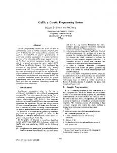
The programming techniques used in writing S T A G E 2 were chosen to make it easy to implement on virtually any machine. I t is coded in the assembly language of a special purpose computer, called FLUS, which was designed to handle the data structures relevant to macro processing: trees, strings, and integers. FLUB does not exist; it is an abstract machine [3] conceived solely for the purpose of coding STAGE2. (A complete description of FLus, giving details of the rationale behind the design, can be found in [10].) To implement S T A G E 2 on a real computer, the FLUB operations are realized as macros which can be expanded b y SIMCS~P [1]. FLus has 28 machine operations and 2 pseudo operations, so t h a t a total of 30 macros must be written. The general organization of the F L u s computer is shown in Figure 2. Each register is made up of three fields, as described in Table IV. The instruction set is given in Table V. Note t h a t m a n y instructions which are commonplace on computers t o d a y are not included. Shift instructions and Boolean operations, for example, are conspicuous b y their absence, the reason being t h a t S T A G E 2 does not require such operations. I t is i m p o r t a n t to keep the purpose Communications of t h e ACM
417
T A B L E IV. Field
BREAKDOWN OF THE FLUB WORD
Minimum Rangeo/Values
Purpose
MEMORY 0, 3
FLG
0,
VAL
PTR
36 general registers
Line Buffer
I
I / 0 Channels
I
I
Indicator bits To hold a single character or the length max(C, L) + 1 of a string. C is the largest integer which represents a character, L is the maximum string length --A, A To address FLUS memory, and act as a general integer accumulator. A is the largest address of the target machine's memory
TABLE V. FLUB MACHINE INSTRUCTIONS I. Data Transfer Operations (a) Register to Register (b) Register to Memory FLG' = ' GET' = '
Processor
VAL'
FIG. 2. Organization of the FLUB cemputer
of this abstract machine firmly in mind when criticizing omissions in the instruction set. FLVB makes no pretense about being a computer for general problems; it is specifically tailored to run STAGE2. All FLVB operands are register names, except target locations for j u m p instructions and the first operand of M E S S A G E " TO '. Each of these consists of two digits. ( G E T and STO each specify a register which contains the desired m e m o r y address.) Each apostrophe in Table V thus represents a single letter or digit• This conforms to the restriction on parameters which is imposed b y S I M C M P , and in fact the lines listed in Table V are exactly the templates for the S I M C M P macros used to translate STAGE2. An advantage of performing all FLVB operations on registers is t h a t it is possible to make a realization of S T A G E 2 more efficient b y using different storage techniques for registers and memory. On one computer, the T i t a n at Cambridge, it was possible to assign flip-flop registers to all of the FL'UB registers. E v e n if the FLUB registers are stored in core, their fields can be left unpacked for rapid access• The fields of the m e m o r y words would be packed to conserve space. All FLUB I / 0 is handled through a generalized I / 0 interface [2] which provides access to a number of channels via a line buffer• Information is transmitted one character at a time between the line buffer and the general registers. Full lines are transmitted between the line buffer and the channels. This view of I / O is quite similar to t h a t proposed for ALGOL 60 [11, 12] and being implemented for ALGOL 6S [13]. T h e code bodies of the macros whose templates are shown in Table V, the I / O interface, and S I M C M P are machine-dependent. T h e y must be hand-coded for each implementation, a task which requires about 8 man-hours. W e have a set of macros whose code bodies are written 418
Communications
of the ACM
PTR
= '
PTR'. VAL
STO'
=
'
'
2. Integer Arithmetic Operations (a) VAL field arithmetic (b) PTR Field arithmetic VAL' VAL
= ' =
' q- '.
PTR'
' -- '
PTR
' =
=
' -- '
' q- '.
PTR
' =
'
PTR
'
' / '
* '.
3. Input~Output Operations (a) Character I/O (b) Line I / 0 VAL ! = CHAR. READ NEXT ! CHAR = VAL ! WRITE NEXT r REWIND ! MESSAGE 'lw TO v ~. Control Operations (b) Conditional TO " IF FLG STOP. TO " TO " IF FLG TO ' " B Y ' TO " IF VAL RETURN BY ' TO " IF VAL TO " IF PTR TO " IF PTR TO " IF PTR
(a) Unconditional
!
NE
' !
NE
' !
NE
'
GE
'
in ASA FORTRAN, and an ASA FORTRAN version of t h e I / O package. S I M C M P is also described in ASA FORTRAN [1]. Thus, if FORTI~AN is available on the target computer, initial implementation of S T A G E 2 is trivial. The initial implementation of S T A G E 2 is via S I M C M P . Because of the inherent weakness of S I M C M P , this implementation will generally not be extremely efficient. To improve the efficiency, one would rewrite the 30 macros to take advantage of the powerful facilities which S T A G E 2 provides for optimization. Then, using these macros and the initial implementation of STAGE2, it is possible t e retranslate STAGE2. Still further improvements in efficiency can be obtained b y hand-coding certain critical routines. W h e n S T A G E 2 is translated b y either S I M C M P or STAGE2, the result Volume 13 / Number 7 / July, 197@
is an assembly code program. It is possible to make measurements on the performance of this program to determine where it is spending most of its time. The critical routines can then be recoded, taking advantage of all available programming tricks. The effort involved in this recoding is miniscule compared with that involved in hand-coding the entire processor. 4.
Conclusions
The purpose of STAGE2 is to provide a tool for constructing machine-independent software. STAGE2 itself is machine-independent, and was designed in such a way that it could be moved to a new machine with virtually no effort and without relying on existing software. I believe that these objectives have been met. As noted in the Introduction, the mobility of STAGE2 has been proved in over 15 implementations. In Pact, in some cases we have found
TABLE VI. IMPLEMENTATIONFOR CDC 6000 SERIES I. Environment
Generalized I/O package I/O buffers System routine Data space
495 words 3019 1622 12000 Total: 17136 words II. STAGE2
FLUBsource code Unoptimized version Optimized version
977 statements 2373 words 1667 words
III. Running time to translate STAGE2 (6400)
Unoptimized version Optimized version
42.254 7.781 36.360 7.233
seconds CP seconds PP seconds CP seconds PP
that reimplementation from scratch was simpler than trying to bring up an existing version for the same machine from a different installation! One of the major questions which arises with a machineindependent implementation such as that described in this paper is how much it costs. What penalty is assessed in terms of reduced efficiency in both time and space? Unfortunately, I cannot answer that question conclusively. To do so would require an implementation of STAGE2 " b y hand" for comparison purposes. As an indication, however, consider the statistics of Table VI. These numbers were obtained from STAGE2, version 2, as implemented on the CDC 6400 at the University of Colorado. At the time the runs were made, we were operating under the standard release of ScoPE 3.1.6. The generalized I/O package was tailored to ScoPE and the 6400, and the system routines were unmodified. I/O buffers were V o l u m e 13 / N u m b e r 7 / J u l y , 1970
provided for nine channels, using the minimum number of words to allow double buffering with the device type assigned to the channel (129 words for disk flies, 1025. words for tape files). Note that with this environment, STAGE2 itself represents less than 13 percent of the total core requirement. In the unoptimized version, each FLUB instruction was translated to COMPASS in the most straightforward way. No attempt was made to take advantage of specia[ operands or to minimize instruction length by retaining frequently used constants in registers. For example, the FLUB statement PTR
A=0-b0
was translated into a fetch of the PTR field of register 0, fetch and add of the same field, and finally a store into the PTR field of A. The optimizing macros took advantage of such operands. In the case noted above, a zero was stored in PTR A (the FLUB register 0 contains 0 in all of its fields). They provide for certain frequently used constants (such as 0 and 1) to be held in registers at all times, and recognize other machine-dependent situations where 15-bit instructions can be used instead of 30-bit instructions. No global optimization is performed; only information derived from a single macro call is examined. Note that although the optimization provided a significant 30 percent reduction in the size of STAGE2, the total length of the optimized version was still 97 percent of that of the unoptimized version. Optimization also provided somewhat faster code--the optimized version required only about 86 percent of the time used by the unoptimized version. Both programs were given the same task: translating STAGE2 to COMPASSusing the optimizing macros. Since the FL~ZB source code for STAGE2 is 977 statements long, STAGE2 translates at roughly 1600 cards per minute with these macros. To date, STAGE2 has been used to translate a comprehensive text processor known as MITEM [14], and a small, interactive editor called MICE. Both of these programs have been implemented on several computers with less than one man-week of effort. We are currently writing a page layout and printing program similar to Text/360 [15] and FORMAW[16], and an interactive BAsic [17] system. I believe that the techniques used in implementing STAGE2, and STAGE2 itself, can help to alleviate the software crisis in which we find ourselves today. By now, most people have learned the value of higher level languages for machine independence. The difficult areas are those in which no high level language is quite suited to the problem. There are two possible tacks to take: (1) twist the problem to fit some existing language; (2) design another language. The major objection to (2) has been the difficulty of implementing a new language, and the realization that the processor will be useless on any other machine. STAGE2 removes the latter constraint. A processor is still difficult to construct, but once done it can be used almost anywhere. C o m m u n i c a t i o n s o f t h e ACM
419
Appendix.
Template
Matching
The templates are organized into a tree, with each pattern element (single character or parameter flag) corresponding to a branch. An example of a template tree is shown in Figures 3(a) and 3(b). Uppercase letters and special characters denote themselves. (A space appears as no character at all.) A lowercase c denotes the end-ofline marker, and a lowercase p the parameter flag. The reason for using c and p is that these branches are not normal characters. As the templates are being read in, each end-of-line flag (or carriage return, if the end-of-line flag is absent) is replaced by a special marker. Each parameter flag is likewise replaced by a marker of another type. If an input line has no end-of-line flag, then the carriage return is replaced by the c marker. Thus there is no internal distinction between an end-of-line flag and a carriage return. Dashed lines in Figure 3(b) represent nodes of the tree. Each branch (character) has a direction associated with it--left to right in Figure 3(b). A given node may have any number of branches directed away from it, but not more than one directed toward it. One node, known as the root, has no branches directed toward it. Several other nodes have no branches directed away from them. These are the leaves of the tree, and are numbered to correspond with the templates. When an input line matches the tree from the root to some leaf, it is recognized as an instance of the template corresponding to that leaf. In Figure 3(b), the branches leaving a node are arranged vertically. Thus the root has two branches leaving it, an S and a parameter flag. The node toward which S is directed has only one branch leaving i t - - t h e character A. We say that one node can be reached from another by a branch if the branch is directed from the first node to the second. Hence the node between S and A can be reached from the root by S.
(1) (2) (3) (4) (5) (6)
SAM = SAM = ' = ' ' = h. ' = ' = SAM =
A. ' ' JOE.
FIG. 3(a). A set of templates Root
S --- A --- M
[_
-J---O---E-
-
[-A---c-FiG. 3(b).
420
--
.
.
.
.
.
.
c--(6)
e-
(5)
(4)
The tree built from the templates of Figure 3(a)
Communications of the ACM
When an input line is read, the end-of-line flag is replaced by a termination element. If there is no end-ofline flag, then the carriage return is replaced. Parameter flag characters are not recognized when input lines are being read; they are only significant in definitions. The input line is matched against the template tree according to the following rules. Rule 1. Rule 2 is applied to the root of the tree and the first character of the input line. Rule 2. If one of the branches leaving the current node of the tree is identical to the current input character, then that branch matches the current input character. Otherwise, Rule 3 is applied to the current node and input character. If the branch matched is an end-of-line marker, the input line is recognized. Otherwise Rule 2 is applied to the node reached from the current node by that branch and the next character of the input line. Rule 3. If one of the branches leaving the current node of the tree is a parameter flag, then Rule 2 is applied to the node reached from the current node by that branch, and the current input character. The branch matches a null string. Otherwise, Rule 4 is applied to the current node. Rule 4. If the current node is the root, the match fails. Otherwise, if the branch entering the current node is not a parameter flag, then Rule 3 is applied to the previous node and the input character which matched the entering branch. Otherwise Rule 5 is applied to the current node and current input character. Rule 5. The substring matched by the branch entering the current node is lengthened by appending the shortest balanced substring of the input line which begins at the current input character. Rule 2 is then applied to the current node and the input character following the new substring. If no such substring can be found, Rule 4 is applied to the previous node and the first input character matched by the parameter flag. If the parameter flag matched the null string, the current input character is used.
If the match fails, the input line is written out. Otherwise the substring which matched the leftmost parameter flag is made parameter 1, the substring which matched the next parameter flag becomes parameter 2, and so forth. (A maximum of nine parameter flags is allowed in one template.) When the parameters have been set, interpretation of the code body begins. As an example of the matching process, consider the set of templates of Figure 3(a) and the corresponding tree of Figure 3(b). The input line SAM = A will obviously match template 1. I t could also match template 2, with A the value of parameter 1, template 3 with SAM and A as parameters, or template 4 with SAM matching the parameter flag. Let us see how the rules operate to determine which of these possibilities will actually occur. Rule Volume 13 / Number 7 / July, 1970
1 gets the whole process started b y calling for application of Rule 2 to the root and the first character of the input string. T h e first character of the input string is S, and there is an S branch directed away from the root of the tree. Thus Rule 2 matches S to this branch. The branch matched is not an end-of-line marker. Hence Rule 2 is applied to the node reached b y t h a t branch, and the next character of the input string. I n our case the next input character happens to be A, and there is an A branch directed away from the node reached b y S from the root. Since this branch is not an end-of-line marker, Rule 2 is applied again. The process continues, with Rule 2 finding a match at each node. Finally, it matches the terminating element of the line to the c branch, and recognizes an instance of template 1. At first glance, one might assume t h a t the input line B = C = A would match template 4 with B = C as the value of the actual parameter. This is not true, however, as an analysis of the scan will show. Rule 1 starts us off as above, but this time Rule 2 does not produce a m a t c h and we must apply Rule 3. There is a parameter marker. Rule 2 is applied to the node reached b y this branch and the current input character (B). Rule 2 fails to produce a m a t c h here also, so Rule 3 is tried. Unfortunately, there is no parameter marker leaving this node, so t h a t Rule 3 sends us on to Rule 4. The current node is not the root b u t the branch entering the current node is a p a r a m e t e r flag. Rule 5 is therefore used to extend the null string which originally matched this flag. B is a balanced substring, so t h a t we now apply Rule 2 to the current node and the space character which follows B. This time Rule 2 produces a match, and we can proceed. The = and the second space are also matched b y Rule 2, but then Rule 2 cannot find a m a t c h for C. Thus Rule 3 is used to advance along the parameter branch, matching the p a r a m e t e r to the null string. We will now have the same situation which occurred at the first parameter m a r k e r - - R u l e s 2 and 3 will be unable to cope with the following node, and eventually Rule 5 will be called upon to extend the substring matched b y the parameter flag. Rule 2 will then find a match for the space following the C, and the whole process will repeat itself. The A will finally be matched to the last parameter flag, and the matching of the terminator will complete the process. The line will thus be recognized as an instance of template 5 rather t h a n template 4. Let us now consider the input line (B = C) = A. This is the same as t h a t of the previous example, except t h a t parentheses have been added to group the characters B = C together. The scan of this line will begin in exactly the same way as the scan of B = C = A. This time, however, when Rule 5 is applied to extend the substring of the input which begins at the first input character is (B = C). We now apply Rule 2 to the node following the p a r a m e t e r marker and a space character from the input string. There is a match, so Rule 2 is applied to the next node and the = character. This matches also, as does the space. We must now apply Rule 2 to the node reached b y the space and Volume 13 / Number 7 / July, 1970
the input character A. Notice here t h a t there is a branch leaving the node which matches A. Thus Rule 2 is applied again to the node reached b y t h a t branch and the terminating element of the input line. We have a m a t c h here, too, and Rule 2 therefore states t h a t the m a t c h is successful. Because of the fact t h a t a p a r a m e t e r flag must match a balanced substring of the input line, (B = C) = A is recognized as an instance of template 4, and (B = C) will be the value of the first actual parameter. If the line were (B = C) = D = A, the reasoning of the previous paragraph shows t h a t it would m a t c h template 5. The template-matching scheme described in this Appendix permits flexibility in the format of a macro call. I t accommodates varying language styles but does require t h a t only one statement be written per line. Spaces are significant. The fact t h a t each p a r a m e t e r flag matches a balanced substring of the input line allows for grouping of text b y parentheses. RECEIVED DECEMBER, 1969
REFERENCES
1. ORGASS,R. J., AND WAITE, W.M. A base for a mobile programming system. Comm. A C M 12, 9 (Sept. 1969), 507-510. 2. POOLE, P. C., ANDWAITE,W.M. I/O for a mobile programming system. Tech. Rep. 69-1, Graduate School Computing Center, U. of Colorado, Boulder, Colo. 3. POOLE, P. C., AND WAITE, W. M. Machine independent software. Proc. ACM Second Symp. on Operating Systems Principles. Dep. of Elec. Eng., Princeton U., Princeton, N. J., Oct. 1969. 4. WAITE, W. M. Building a mobile programming system. Comput. J. 13, (Feb. 1970), 28-31. 5. WAITE, W. M. The STAGE2 macro processor. Tech. Rep. 69-3, Graduate School Computing Center, U. of Colorado, Boulder, Colo. 6. WAITE, W. M. A language independent macro processor. Comm. A C M 10, 7 (July 1967), 433--440. 7. McKEEMAN, W.M. Peephole optimization. Comm. A C M 8, 7 (July 1965), 443--444. 8. HORWITZ,L. P., KARP, R. M., MILLER,R. E., ANDWINOGRAD, S. Index register allocation. J. A C M 18, 1 (Jan. 1966), 4361. 9. LowRY, E. S., .ANDMEDLOCK,C.W. Object code optimization. Comm. A C M 12, 1 (Jan. 1969), 13-22. 10. WAITE,W.M. Building a mobile programming system. Tech. Rep. 69-2, Graduate School Computing Center, U. of Colorado, Boulder, Colo. 11. IFIP/WG 2.1. Report on input-output procedures for ALGOL 60. Comm. A C M 7, 10 (Oct. 1904), 628-630. 12. DEVOGELAERE, R. A set of basic input-output procedures. Comm. A C M 11, 8 (Aug. 1968), 567-573. 13. MAILLOUX,B . J . Private communication. 14. POOLE, P. C., .AND WAITE, W. M. A machine independent program for the manipulation of text (User manual). Tech. Rep. 69-4, Graduate School Computing Center, U. of Colorado, Boulder, Colo. 15. REED, S.L. TEXT360. 360D 29.5.002, IBM Program Library, Aug. 1967. 16. BERNS, G. M. Description of FORMAT, a text processing program. Comm. A C M 12, 3 (Mar. 1969), 141-146. 17. Dartmouth College Computer Center. B A S I C (3rd ed.). Dartmouth CCC, Hanover, N. H., 1966. Communications of the ACM
421