Behavioral simulation is used in our constraint-driven, top-down hierarchical design methodology 1] to verify the design early. In digital domain, the behavior of a ...
Behavioral Representations for VCO and Detectors in Phase-Lock Systems Edward Liu and Alberto L. Sangiovanni-Vincentelli Department of Electrical Engineering & Computer Sciences University of California Berkeley, California 94720
Abstract This paper presents behavioral representations for detectors and voltage-controlled oscillators that are independent of circuit architectures. Parameter extraction techniques are described. Finally, parameter extraction for a VCO is demonstrated, and an example PLL constructed using the models is simulated and veri ed against actual chip measurements.
1 Introduction Behavioral simulation is used in our constraint-driven, top-down hierarchical design methodology[1] to verify the design early. In digital domain, the behavior of a circuit is de ned to be the function to be implemented independent of the architecture and/or schematics. Behavioral simulation in digital circuits can reduce substantially the design cycle. In the analog domain, behavioral simulation is often confused with macromodeling where an approximate model is built with components that are typical circuit components such as capacitors, controlled sources, and resistors. The notion of behavior as given for digital circuits could be extended to the analog domain. However, since the high-level analog functions are very simple, the power of behavioral simulation to uncover potential problems is greatly reduced. In analog circuits, malfunctioning is mostly due to the non-ideal behavior of the components. Thus, an e�ective behavioral simulation strategy has to be based on high-level models of second order e�ects. We have developed models for A/D converters that are based on these principles[2][3][4]. To have a useful behavioral simulation environment, we need to develop models for most of the high-level analog functions. In this paper, we propose behavioral representations for voltagecontrolled oscillators (VCO) and detectors that are essential circuit components in any phase-lock system. The representations include su�cient second order e�ects for realism, are independent of the circuit component architectures, and are general for use in many diverse phase-lock system modeling applications. The paper is organized as follows: Behavioral models for sinusoidal and square wave VCO's are presented in Section 2 and 3, respectively. In Section 2.3, results of parameter extraction for a VCO are compared with SPICE and macromodeling results. A behavioral model for detectors and parameter extraction techniques are presented in Section 4. Finally, in Section 5, a phase-locked loop application is presented with simulation results compared with actual measurements.
2 Sinusoidal VCO A sinusoidal voltage-controlled oscillator (VCO) ideally accepts as input a voltage, v , and outputs a sinusoidal signal whose
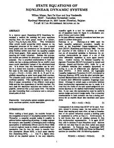
frequency is linearly proportional to the input voltage. In a practical VCO, the frequency is nonlinearly related to the input voltage, the output contains harmonic components (distortion), and the phase has random variations (phase noise). Previous work[5] [6] includes macromodels for SPICE which do not model distortion or noise e�ects. In our model, non-ideal behaviors can be captured by a two stage model shown in Figure 1, where stage
v Stage1 Ideal VCO
x
Stage2 Nonlinear Dynamic Element
(fundamental)
Figure 1: Two stage VCO model
(fundamental and harmonics)
1 is an ideal VCO to generate a signal, x, followed by a nonlinear dynamic stage 2 whose output, y , contains fundamental and harmonic frequencies. Given the input v , the output of stage 1, x, is given by f = g (v ) (1) �(t) = 2�
Z t f (� )d� + (t) 0
(2)
x(t) = cos(�(t)) (3) where g is the nonlinear relationship between the frequency f and v , � is the instantaneous phase, and is any stationary random process to represent phase noise (usually Gaussian with mean 0 and variance � 2). Since f and are in general timevarying, x is not sinusoidal. When such a signal is fed into the nonlinear dynamic stage 2, the output y is given by y=
X1 Z � � � Z hn(�1; : : :; �n)x(t ? �1) : : :x(t ? �n)d�1 : : :d�n
n=1
(4) where hn are the Volterra kernels[7] of stage 2. To solve (4), we make the quasi-static approximation.
2.1 Quasi-static approximation
In a practical sinusoidal VCO, the phase noise is small, the control range is small, and the control voltage varies much slowlier than the frequency f . Therefore, we propose to determine VCO model parameters for a range of constant values of v using (4). The quasi-static approximation means that during simulation for time-varying v (t), we use the model parameters corresponding to instantaneous values of v . If v is a constant, then x is a pure sinusoidal, and (4) has solution,
y=
XN jAn(!)jcos(n�(t) + 6 An(!))
n=0
y
(5)
2.2 VCO parameter extraction
Parameters g , , and coe�cients An can be estimated from VCO outputs y (t; v ) for di�erent xed values of v obtained from SPICE simulations or laboratory measurements. The following steps are followed: (a) For a constant input v , estimate from output y the fundamental frequency, f , using the sinusoidal minimum error method[8] or the complex demodulation method[9]. In the latter case, the idea is to multiply y (t; v ) with ej 2�ft^ , followed by low pass ltering to get z (t), where f^ is our guess of f . If f^ = f , the phase of z(t) is constant; otherwise, it is slowly time-varying for f^ � f . Using NewtonRaphson[10], solve for f such that the phase of z (t) is constant. (b) With f known, the magnitude and phase of the fundamental and harmonics can be similarly calculated using demodulation. Speci cally, magnitude is the average of 2jz (t)j and phase is the average of ?6 z (t). (c) Repeat (a) and (b) for di�erent v to estimate the nonlinear function g for equation (1), as well as for more data points on An (! ) in (5). (d) Estimate � for (2) from laboratory measurements or by hand analysis[11]. (Notice that SPICE does not simulate noise in the time domain.) (e) Assign value for 0, which is the only initial condition.
v n 1 2 3 4 5
0 (gain,phase) (2.88V, -3.72) (1.63mV, -0.89) (78.2mV, -3.02) (30.2� V, -1.90) (6.65mV, -1.37)
1 (gain,phase) (2.88V, -4.10) (2.00mV, -1.29) (78.0mV, -4.17) (45.6� V, -0.92) (6.63mV, -3.29)
2 (gain,phase) (2.88V, -4.47) (2.02mV, -1.77) (78.2mV, -5.27) (36.3� V,-1.08) (6.69mV, -5.12)
Figure 3: Behavioral parameters for Pierce oscillator macromodels in [5] do not model harmonics, so the lower error bound is given by the rst order residual error shown in Figure 5. Thus, the behavioral model is more accurate than macromodels, as well as faster since evaluating the behavioral model only involves evaluating the function in (5). 3 2 1
volts
where N is the order of approximation, ! = ddt� is the constant frequency, and An are complex coe�cients given by A0 (!) = 12 H2 (!; ?!)ej ; A1(!) = (H1(!)+ 43 H3(!; !; ?!))ej ; A2 (!) = 21 H2(!; !)ej ; A3(!) = 14 H3(!; !; !)ej ; etc Summarizing, the VCO model consists of stage 1 described by (1), (2), and (3), and stage 2 described by (5). The model parameters are the function g , the phase noise , and the complex coe�cients An .
0E+0 -1 -2
-3 Figure 4: SPICE simulations and residual error in behavioral 70 90 110 130 approximation 50 Time(ns)
150
0.2
2.3 Example VCO parameter extraction volts
0.1
6V
M2
0E+0
-0.1
CC V(out)
L RX
Figure 5:-0.2 Residual errors in rst and fth order approximation 50
M1
C2
RL
C1
Figure 2: Pierce oscillator -6V
Shown in Figure 2 is a schematic of a Pierce oscillator with varactor tuning that consists of circuit elements M 1 = 15�m=1�m, M 2 = 35�m=1�m, L = 129:75nH , C 1 = C 2 = 20pF , RL = 100 , RX = 1M , and voltage-controlled capacitor CC = 2pF=V . Its behavioral model parameters (Figure 3) were extracted from three SPICE transient simulations for three different control voltage v . Figure 4 shows the SPICE output for v = 0 and the residual error in the 5th order (N=5) behavioral approximation used in this case. In contrast, the SPICE
70
90
110 time(ns)
130
2.4 Error analysis
To estimate the error of the quasi-static approximation when the control input is not constant, we let the frequency, f , be modulated by a sinusoidal signal with small amplitude (narrow band frequency modulation). For instance,
f = g(v) = fc + fm cos(2�fm t) where is the modulation index, and fm is the modulation frequency. Assuming the phase noise is negligible, it can be shown that the error of the quasi-static approximation is bounded by an error term proportional to . As a result, when the modulation index is su�ciently small, the error becomes negligible.
150
3 Square wave VCO v delay 1
b1
delay 2
b2
delay 3
b3
Figure 6: Square wave VCO with m = 3 delays In addition to oscillators with sinusoidal outputs, there are oscillators with square wave outputs. In contrast to the sinusoidal VCO where the waveform is represented by (5), the waveform of a square wave is represented by the zero crossings (low-to-high and high-to-low transition times). In general, a VCO consists of m delay elements connected in a ring structure (Figure 6). 1 seconds, where Each of the m outputs are phased shifted by 2mf f is the frequency of the VCO. We represent the j th transition time of output i with yi (j ) as shown in Figure 7. Similar to b1
b2
b3
state y1(1)
y1(2)
y2(2) Figurey2(1) 7: VCO square waveforms y3(1)
y3(2)
y1(3)
0 1 2
y2(3) y3(3)
the sinusoidal VCO, the frequency is controlled by the input v using equation fi = gi(v) (6) where gi represents control relationship for element i, and fi represents the e�ective frequency of delay element i. Unfortunately, v varies considerably in a square wave VCO; therefore, the quasi-static approximation is not appropriate in this case. The transition times are determined by the delay between adjacent delay elements. For example, yi (j ) for i 6= 1 is equal to yi?1(j ) plus the delay of element i. Because of this relationship, it is convenient to use a recursive de nition for yi (j ),
Z y (j) f (� )d� + (y (j)) ? (y (j)); i 6= 1 (7) i i i i i? 1 y ? (j ) Z y (j) f (� )d� + (y (j)) ? (y (j ? 1)); i = 1 (8) � = 2�m � = 2�m
de ned only when the input waveform and the VCO waveform have the same frequency. As a result, this approach cannot be used during phase-locked loop acquisition. Another problem is that the phase characteristic depends on the shape of the waveforms, so the characteristic is not de ned until input signals are applied. As a result, the phase characteristic is not appropriate as a behavioral representation. Detectors are classi ed into two broad categories[12]: multipliers (zero memory circuits) and sequential circuits (with memory). In this paper, sequential circuits are represented by state machines with analog inputs, a and b, analog outputs g (a; b), and clock triggered by zero crossings of a and b. Moreover, the same representation can be used for multipliers if they are considered as state machines with a single state and no clock. In general, all detectors can be conveniently represented by a state transition table such as the one shown in Figure 8 for a phasefrequency detector. Signals a, b, and c are the input, VCO, and output waveforms, respectively. The rst column is the state number; the second column is the next state if a crosses zero; the third column is the next state if b crosses zero; td are gate delays of next state logic; the last column is the output g (a; b) for each state. State transition tables for common detectors are shown in Figure 9. Since all known detectors can be written in this representation, this representation is general and independent of the circuit architecture.
Figure 8: Behavioral model for phase frequency detector Phase Detector
1
i
ym (j ?1)
i
i i
i m
where i is the random phase noise of element i. Summarizing, the model consists of (6), (7), and (8). Model parameters are the number of delay elements m, the voltage-control relationship gi , the phase noise i , and the initial condition y1 (1).
4 Detectors A detector compares two signals (input waveform and VCO waveform). Traditionally, circuit designers represent a detector by its phase characteristic which plots the average product of the input waveform and the VCO waveform as a function of the phase di�erence between the two waveforms. One problem with this modeling approach is that the phase characteristic is
Sampling Detector
Chopping Detector
g(a,b) 0 a * b
XOR Detector
-1
x
i
i
a crosses b crosses c (next, delay) (next, delay) g(a,b) (1, td ) (2, td ) 0.0 (1, td ) (0, td ) Iup (0, td ) (2, td ) Idown
cross zero b g(a,b)
XOR
cross zero b g(a,b)
0 1
a
0 1
1 0
a (when 1 0
Figure 9: Common switch detectors opens)
4.1 Detector parameter extraction
a -a
cross zero a b g(a,b) 2 3
1 0
2 0 3 1
3 2
0 1
For a given detector type, the next state logic is xed. Nonidealities are the transition delays, td , and deviations of the output function. td is computed by measuring the total gate delays in the next state logic. Typically, g (a; b) is very simple; for instance, g (a; b) = c0 + c1 a + c2 b + c3ab. Its non-idealities include constant o�set error in c0 and multiplier gain error in c3. All four coe�cients c0 : : :c3 can be extracted using four DC SPICE simulations with di�erent a0 s and b0s, and solving for the coe�cients in a system of four equations.
Iup Idown Iup Idown
5 Phase-lock loop simulation Using the models presented, we constructed a high-level model of a real phase-lock loop[13]. The loop lters are modeled with di�erential equations, the VCO is modeled with a square wave VCO with one delay element (m = 1, output fed directly back to input), and the phase-frequency detector is modeled as in Figure 8 with td = 0. Relevant system parameters, such as acquisition time and jitter gain function, are computed from transient simulations. In our prototype, the VCO output, b, is modeled as a switching function, which is completely characterized by the transition points, y1 (j ). Traditional integration algorithm for di�erential equations cannot handle this type of system because b is non-di�erentiable. However, the problem is much easier because the di�erential equation solver needs only determine the transition time points, y1 (j ), which are de ned by (8). For example, in (8), we need to nd the upper integration limit, y1 (j ), to satisfy the equation. As a result, we solve for y1 (j ) by using an iterative solver on top of an integration algorithm. For prototyping, we implemented the iterative false position method[10] on top of the trapezoidal integration algorithm to search for the points. Using this algorithm, the simulation speed is dramatically increased, while preserving numerical stability. A prototype simulator has been implemented using the C++ language on a DECstation 5000. Figure 10 shows the output frequency as the input frequency is stepped from 120MHz to 138.5MHz, compared with the output frequency measured from an experimental chip. From Figure 11, measured overshoot (34%) and settling (8�s) agree with simulation (33%, 7�s). Next, the input frequency is varied to probe the system for the jitter gain function. From the data, -3db cross-over frequency is estimated to be 470KHz which agrees with the theoretical value of 410KHz. For both examples, the circuit was simulated from time zero to 40�s (using DEC5000 CPU time 17 minutes), corresponding to 5165 VCO cycles. If the same analysis is done with SPICE, the time step size should be about 100ps since the VCO period is 8:3ns. So, assuming SPICE takes 0:5s to compute a time point, SPICE would take at least 2 days for each of the examples.
130e6
Figure 11: Measured PLL acquisition
110e6
20e-6 Time(sec)
SPICE simulation time, and the simulation results agree with measured chip data. Finally, because our models are independent of circuit architecture, we can model and simulate a wide range of PLL circuits. We have presented a way to model and simulate PLL's in a reasonable amount of time with minimal loss of accuracy.
Acknowledgements
The authors acknowledge the many helpful discussions by the members of CAD and IC groups at U. C. Berkeley. We especially thank Prof. P. R. Gray for his helpful advice on the square wave VCO model. This project is supported by the Semiconductor Research Corporation. Its support is gratefully acknowledged.
References [1] H. Chang, et al. \A top-down, Constraint-Driven Design Methodology for Analog Integrated Circuits", Proc. IEEE CICC, May 1992 [2] E. Liu, et al. \A Behavioral Representation for Nyquist Rate A/D Converters", Proc. IEEE ICCAD, Nov 1991 [3] E. Liu, et al. \Behavioral Modeling and Simulation of Data Converters", Proc. IEEE ISCAS, May 1992 [4] G. Gielen, et al. \Analog Behavioral Models for Simulation and Synthesis of Mixed Signal Systems", Proc. EDAC, March 1992 [5] Mark Sitkowski, \The Macro Modeling of Phase Locked Loops for the Spice Simulator", IEEE Circuits and Devices Magazine, v7 n2 March 1991 p. 11-15 [6] E. Tan, Phase-Locked Loop Macromodels, Master's Thesis, (Call no. T7.49 1990 T283) U.C. Berkeley, August 1990. [7] D. Weiner, J. Spina Sinusoidal Analysis and Modeling of Weakly Nonlinear Circuits, pages 274-278, Van Nostrand Reinhold Company, New York, 1980
150E+6
VCO Frequency
Differential voltage control (Frequency)
150e6
[8] B. Boser, et al. \Simulating and testing oversampled analog-to-digital converters", IEEE Trans. Computer-Aided Design, vol. 7, pp. 668-674, June 1988
130E+6
[9] D. Brillinger Time Series Data Analysis and Theory, Expanded Edition McGraw-Hill, New York, 1981
Figure 10: Simulated PLL acquisition 10E-6 20E-6
110E+6 0E+0
[10] W. Press, et al. Numerical Recipes The Art of Scienti c Computing, pages 263-266, Cambridge University Press, 1988. 30E-6
Time (sec)
6 Summary We have presented behavioral models for VCO and detectors in phase-lock systems. Parameter extraction techniques to identify the models have been described, and the techniques were used to extract parameters for an actual VCO. Furthermore, we used these models to model and simulate an actual PLL. The simulation time is signi cantly lower than an estimated
[11] 40E-6 A. Abidi, R. Meyer, \Noise in Relaxation Oscillators", IEEE Jornal of SolidState Circuits, vol. SC-18, No. 6, December 1983 [12] F. M. Gardner, Phase-lock Techniques John Wiley & Sons, Inc., New York, 1979 [13] K. M. Ware \A High-Frequency Integrated CMOS Phase-Locked Loop", IEEE Journal of Solid-State Circuits, vol. 24, No. 6, December 1989
40e-6