Jun 10, 2005 - register. I-type instructions are also used for memory load and stores and some ... Table 4.0 â Register names and assignments (adapted from ...
Paper submitted to: 2nd UK Embedded Forum 2005 (Last edited: 10 June 2005 - ZMH - UK embedded forum 2005 - MIPS v09.doc)
The PH Processor: A soft embedded core for use in university research and teaching Zemian M. Hughes, Michael J. Pont and Royan H. L. Ong
Embedded Systems Laboratory, University of Leicester, University Road, LEICESTER LE1 7RH, UK. http://www.le.ac.uk/eg/embedded/
Abstract For the developer of embedded systems, the division between “software” and “hardware” is becoming rather blurred. With the rapid expansion in the availability of FPGAs, design software (using VHDL and related languages) and various “soft” processor cores, it is now becoming possible to create “custom processor” which matches the needs of a particular application. In addition to have numerous commercial applications, such processors are core components of many university research and teaching programmes. In this paper we describe the “PH Processor”, which is freely available for use in university research and teaching.
Acknowledgements The processor described in this paper is based on a design by David A. Patterson and John L. Hennessy which is presented in their book “Computer Organization and Design” (Patterson and Hennessy, 2004). We are grateful to Prof Patterson and Prof. Hennessy - and their publishers - for granting us permission to release details of what we refer to here as the “PH Processor”. The project described in this paper was supported by the UK Government (EPSRC DTA award). Work on this paper was completed while MJP was on Study Leave from the University of Leicester.
1. Introduction Over recent years, we have considered various ways in which time-triggered software architectures can be employed in embedded systems where reliability is a key design consideration (e.g. Pont. 2001; Pont, 2003; Pont and Banner, 2004). The techniques described in these studies have involved creating software for industry-standard hardware platforms, such as the 8051 microcontroller (Pont, 2001), ARM processor (Pont and Mwelwa, 2003) or PC platform (Pont et al., 2003).
Developing reliable applications using this approach can be effective, but there is a mismatch between generic processor architectures and time-triggered software designs. For example, most processors support a wide range of interrupts, while the use of a (pure) time-triggered software architecture generally requires that only a single interrupt is active on each processor.
This leads to design
“guidelines”, such as the “one interrupt per microcontroller rule” (Pont, 2001). Such guidelines can be supported when appropriate tools are used for software creation (e.g. see Mwelwa et al., 2003; Mwelwa et al., 2004). However, it is still possible for changes to be made (for example, during software maintenance or upgrades) that lead to the creation of unreliable systems.
The present paper represents the first step in a new research programme in which we are exploring an alternative solution to this problem. Specifically, we are seeking to develop a novel processor, which is designed to support only time-triggered software. This approach has become possible since the advent of reduced cost of FPGA chips with increasing gate numbers (Gray, 2000). With VHDL and related hardware descriptive languages reaching higher levels of abstraction, the production of radiation hardened FPGA chips (e.g. Atmel AT40KEL040), and Fault tolerant techniques (e.g. Sinha et al., 2000; Hammarberg et al., 2003), such as TMR (triple modular redundancy) (Jasinski and Pedroni, 2004), FPGA-based designs are being used in safety-critical applications, such as the aerospace industries. In the present paper we describe the conventional processor platform which we have assembled in order to support our research in this area.
Since 32-bit processors are becoming more widely used
within embedded systems, it was decided that a well documented 32-bit RISC architecture would be an appropriate platform for our work in this area. The specific platform chosen was what we will refer to here as the “PH processor”: we have based this design on that described by (Patterson and Hennessy, 2004), with a number of extensions.
Page 2
The paper is organised as follows. In Section 2 we outline origins of the MIPS microprocessor which the PH processor is based. Section 3 gives a brief overview of the PH processor whilst Section 4 describes the in depth specifications which the processor is design to. Section 5 introduces the hardware platform with which the PH processor was created followed by Section 6 giving more in depth discussion of key implementation details. Section 7 then describes the process of taking C programs and loading them to the hardware and the features of the PH processor debug application. This is then followed Section 8 with a conclusion for all the details describe within this report.
2. The origins of the PH processor The MIPS (Microprocessor without Interlocked Pipeline Stages) processor was the product of a team led by by John Hennessy at Stanford University in 1981 (Stanford, 2003). The aim was to dramaticaly increase the speed of a processor by the use of deep instruction pipelining. However pipeline designs of that era required interlocks for multi-cycle instructions to pause the processor from loading new data whilst the current instruction was executing. The hardware required to setup these locks where generaly large and complicated which had a significant impact on the speed of processors (Hennessy, 1982). Hennessy’s aproach was to create a simple RISC instruction set by eliminating a number of useful complex instructions such as multiply and divide that take multiple clock cycles to execute, and create an instruction set where all instructions take only one clock cycle (Hennessy, 1981). In doing so the pipeline no longer required the complex interlock mechanisms and formed an effcient procesor design which is at the heart of many modern MIPS and RISC processors designs used in research and many devices such as Sony Playstations, PDA’s and large physics processing computers (MIPS Technologies, 2005).
3. The PH Processor There are a range of MIPS processors available. Our intention was to create a cut-down version of a R2000 processor which would be compatible with the MIPS I ISA (Instruction Set Architecture) (Kane and Heinrich, 1992), excluding patented instructions. Our design followed the outline provided by Patterson and Hennessy (2004) and therefore called it the “PH Processor”. Briefly, this is a 32-bit processor with 32 registers and a 5-stage pipeline. The processor also includes the system coprocessor CP0, to support precise exceptions (see Section 6.9).
Page 3
4. PH Processor specifications We describe the processor specification in this section. Except where otherwise stated, much of the information presented here is adapted from Patterson and Hennessy (2004). 4.1 Instructions There are three main instruction categories, R-type (register format) I-type (immediate format) and Jtype (Jump format), all of which are 32 bits wide.
Figure 4.1 – R-type instruction format (adapted from Patterson and Hennessy, 2004)
R-type instructions have two source registers and one destination register: the function applied to the source registers is defined in the ‘funct’ field. R-type instructions are easily identifiable because they have an ‘opcode’ value equal to zero.
Figure 4.2 – I-type instruction format (adapted from Patterson and Hennessy, 2004)
I-type instructions have one source register, one 16bit immediate source value and one destination register. I-type instructions are also used for memory load and stores and some conditional branches.
Figure 4.3 – J-type instruction format (adapted from Patterson and Hennessy, 2004)
J-type instruction is primarily used for a jump instruction where the program counter is loaded with the program counters top most significant bits and the lower 26-bit immediate address value. There are also a number of “pseudo instructions” which are not implemented directly in the processor hardware but are represented as a combination of (hardware) instructions when code is compiled.
4.2 Registers The register bank contains 32 x 32-bit registers, where register ‘r0’ is unique in that it is always held equal to zero and write instructions to it are ignored. Register ‘r31’ is a general purpose register but is Page 4
used specifically for holding the return address across function calls. Details of the registers in the register bank and there assignments are shown in Table 4.0. Name
Number
Use
Preserved across Call
$zero
0
Constant Value 0
$at
1
Assembler Temporary
$v0-$v1
2-3
N.A. No
Values for Function Results
No
and Expression Evaluation
$a0-$a3
4-7
Arguments
No
$t0-$t7
8-15
Temporaries
No
$s0-$s7
16-23
Saved Temporaries
Yes
$t8-$t9
24-25
Temporaries
No
$k0-$k1
26-27
Reserved for OS Kernel
No
$gp
28
Global Pointer
Yes
$sp
29
Stack Pointer
Yes
$fp
30
Frame Pointer
Yes
$ra
31
Return Address
Yes
Table 4.0 – Register names and assignments (adapted from Patterson and Hennessy, 2004)
The program counter ‘PC’ is separate to the register bank and is not directly accessible, only through jump and branch instructions for writing and jump and link for reading. The 2 least significant bits of the PC are always zero as each instruction is 32 bits wide, word aligned and separated by an address of 4. 4.3 Branch Conditions The processor does not contain condition flags but uses conditional branch instructions to make decisions. There are two branch instructions, BEQ (Branch Equal) and BNE (Branch Not Equal) which if combined with SLT (Set Less Than) or SLTI (Set Less Than Immediate), provides the necessary conditions required to satisfy ‘C’ whilst keeping the number of instructions to be implemented to a minimum. Name
Mnemonic Pseudo
Compiled to
Branch Equal
BEQ
-
BEQ
Branch Not Equal
BNE
-
BNE
Branch Less Than
BLT
Pseudo
Branch Greater Than
BGT
Pseudo
Branch Less Than or Equal
BLE
Pseudo
Branch Greater Than or Equal
BGE
Pseudo
Logic
SLT $t0, $s0, $s1
if ($s0 < $s1) $t0 = 1
BNE $t0, $0, Less
if ($t0 != 0) goto Less
SLT $t0, $s1, $s0
if ($s0 > $s1) $t0 = 1
BNE $t0, $0, Greater
if ($t0 != 0) goto Greater
SLT $t0, $s1, $s0
if ($s0 > $s1) $t0 = 1
BEQ $t0, $0, LEqual
if ($t0 = 0) goto LEqual
SLT $t0, $s0, $s1
if ($s0 < $s1) $t0 = 1
BEQ $t0, $0, GEqual
if ($t0 = 0) goto GEqual
Table 4.1 – Conditional branches (adapted from Patterson and Hennessy, 2004)
Page 5
4.4 Load and Store Memory load and store instructions follow the I-type instruction format where the pointer in the base register ‘rs’ is added to the immediate offset value to from an address where a value is loaded or stored to the destination register ‘rt’.
Figure 4.4 – I-type instruction format (adapted from Patterson and Hennessy, 2004)
The RAM is 32 bits wide but byte addressable and requires that 32-bit words are word aligned as are 16-bit half words aligned to half-word boundaries as shown in Figure 4.5. There are instructions in the MIPS I ISA to support unaligned word load and stores such as LWL (Load Word Left) and LWR (Load Word Right) but these are patented by MIPS Technologies and are not implemented here.
Figure 4.5 – Data alignment (adapted from Patterson and Hennessy, 2004)
4.5 Pipelining Pipelining is a technique which split up the instruction path into stages, to allow multiple instructions to “execute” simultaneously. We provide brief overview of the pipeline used in the PH Processor in this section, then go on to consider the mechanisms used to deal with control and data hazards. a) Overview
The PH Processor has a 5-stage pipeline (Figure 4.6), where there are two separate ports to memory, one for instruction fetch and one for data access: this is often referred to as a “Harvard” architecture.
Figure 4.6 - MIPS 5-stage pipeline (adapted from Patterson and Hennessy, 2004)
Page 6
Each pipeline stage takes one clock cycle. Between each stage we require pipeline registers to store the outcome of the previous stage. b) Control Hazard When making a conditional decision - such as a branch command where the decision is not taken until the command is executed - the pipeline stages will already have been loaded with the “next” instructions before the decision is made. If care is not taken, we will execute the “next” instructions, regardless of the result of the conditional decision: this possibility is known as a control hazard.
To avoid control hazards, it is best to identify the outcome of conditional decisions as early as possible in the pipeline. For example, if we identify the results of a branch command in the ID (Instruction Decode) stage, there will only be one (possibly) unwanted instruction in the pipeline.
One method to remove this unwanted instruction is to detect and stall the pipeline after the branch instruction by forcing a ‘nop’ command directly after the branch. However, a more efficient solution is to have the compiler reorder its output in such a way that an instruction which must (always) be executed regardless of the branch decision is placed directly after the branch instruction: this is known as the branch delay slot. Note that - if no suitable instruction can be identified - then the compiler can place a ‘nop’ command in the delay slot.
In the PH Processor, we include no hardware features to deal with control hazards and assume that a suitable compiler is employed (see Section 7.2). c) Data Hazard When a “current” instruction is dependant on results of a “preceding” instruction we may have what is known as a “data hazard”. Such a situation arises when the preceding instruction has not reached the write-back stage (and updated the register file) when the current instruction requires the register value.
To deal with data hazards, a forwarding unit can be used to check if a register to be read in the EX (Execution) stage is to be written to in the MEM (Memory) or WB (Write Back) stages. If this “read before write” situation arises then the forwarding unit routes the register value from either the MEM or WB stage to the EX stage. If both the WB and MEM stage have there own copy of the register then the MEM stage value is forwarded to the EX stage (as it is the most recent copy). Page 7
Note that there is one condition when a value cannot be forwarded: this is when an instruction following a load instruction is dependant on the value to be loaded from memory for the register in use. This is because there is no way to force the value out of the data memory any faster than its read time (which is after the MEM stage). The solution to this is similar to that described for control hazards in Section 4.5b: in the case of data hazards, we can use a load delay slot to place a ‘nop’ instruction directly after a load instruction in situations where the following instruction is dependant on the output of the current instruction. This solution may not always be ideal as it will increase code size, so a data hazard unit can be used to stall the IF (Instruction Fetch) stage to force hardware ‘nop’ command instead.
The present implementation of the PH Processor follows Patterson and Hennessy (2004) and uses a hardware data-hazard unit.
Page 8
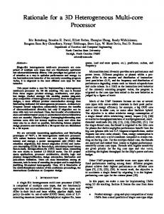
5. Hardware platform used To test the design outlined in the previous sections, the processor was set up on an FPGA as shown in Figure 5.0. Implemented in this way, the core contains its own instruction and data memories and the device can be programmed and debugged through the serial UART, which connects to a PC application that can monitor everything down to the control and data paths.
Figure 5.0 – Layout of the PH core and supporting systems
The BL (Buttons and Lights) block uses memory map IO to interface to the onboard led’s and IO pins. The timer is attached on the data bus where the necessary registers are easily addressed through normal memory load and store instructions.
Our current implementation of the PH processor was created using VHDL with Xilinx ISE tools targeting a Xilinx 200K gate Spartan 3 FPGA chip on a Digilent Spartan 3 development board. There are 216KBits of block RAM on the chip and 1MB of SRAM on-board. The board contains a serial port, led’s, seven segment display, buttons and switches and costs about £60 (UK pounds).
Figure 5.1 – Digilent Spartan 3 development board (Digilent, 2004)
Page 9
6. Implementation Details The core was implemented to run all (non patented) integer instructions in order to create a simple processor core base. Note that co-processor devices, extra instructions and peripherals may be easily added to the design. 6.1 Pipeline The details of the 5-stage pipeline used closely resembles the setup describe by Patterson and Hennessy (2004), with one exception. As discussed by Brej (2002), the branch instructions as in the Patterson and Hennessy design require a conditional test on two registers in the ID stage: the values required are obtained from the register file, not from the most recent forwarded value from the consecutive stages. The forwarding unit makes available the most recent value to the EX stage and - since we wish to keep the branch execution in the ID stage to minimise the number of delay slots after a branch instruction we could add an extra separate forwarding unit. This would work but would complicate the design. Brej (2002) describes a modification which shrinks the ID stage to half a clock cycle: this means that the condition branch instructions can use the forwarded values in the EX stage and update the PC before the next clock cycle, thereby maintaining the one-branch delay slot. This is an efficient solution and the Brej implementation was used in the present PH Processor design.
Figure 6.0 – Modified 5-stage pipeline (Brej, 2002)
Reducing the WB stage to half a cycle also aids with synchronous RAM register descriptions where load and stores are not simultaneous. 6.2 Register Bank Two implementations of the register file were created, one synchronous (using block RAM) and one asynchronous (using distributed RAM).
In many circumstances the synchronous block RAM
implementation is preferable in that it is faster and does not use a large amount of logic. However, while the distributed RAM is created directly from logic and look up tables (which might be scarce once a system design is complete) it does have the advantage that the RAM can be read and written at the same time. In the PH Processor implementation, the choice of register-file implementation can be Page 10
made when compiling the design. Since the synchronous block RAM must be clocked for both read and writes, one half of the clock cycle is used for writing whilst the other half is used for reading. In order to generate the register file which contains one write port and two read ports, two dual-ported RAMs with identical copies of the register values are used (Figure 6.1). This allows simultaneous reads of two registers as required. Also if the register to be read is ‘r0’ then the output must be zero, which is achieved by blocking any writes to ‘r0’ where only the initialised unaltered RAM value of zero is read.
Figure 6.1 – Block RAM register file configuration
6.3 Control As with the Patterson and Hennessy (2004) design there are two control units in the PH Processor, the main control unit in the ID stage for non R-type instructions and an R-type controller in the EX stage which not only controls the ALU but also the Shifter and R-type jump commands. It is thought that splitting the control unit into two increases the instruction decoding speed which is useful since – as discussed in Section 6.1 - the ID stage has been shrunk to half a clock cycle. 6.4 ALU The ALU is made up of combinational logic where the two input values are run through each of the logic operations (AND, OR, NOR and XOR) and a selectable adder/subtract unit where the required value is selected through a multiplexer. This solution was chosen purely for simplicity. The ALU also detects overflows which are used to generate exceptions for certain instructions and the SLT instructions are also implemented in the ALU.
Page 11
6.5 Shifter Barrel shifters (as used in processors such as ARM: (Furber, 2000), are very fast in ASICs, but in FPGA they require 32 x 32-bit multiplexers which take up a large amount of FPGA logic. A solution to this problem and to maintain a variable shift amount left or right in one clock cycle is to implement a funnel shifter (Brej, 2002). The funnel shifter passes the value to be shifted through 5 multiplexers which are wired to give the corresponding shift amounts (1, 2, 4, 8 and 16). The bits in the ‘shamt’ field of R-type instructions select the individual multiplexers to get the overall required shift amount. To keep things simple, the values pass through two sets of 5 multiplexers, one for shift right and one for shift left, with a multiplexer to select the required shift direction. 6.6 Memory The data memory is 32 bits wide but needs to be byte addressable, so that instructions LW, LH, LB can load 32-bit, 16-bit and 8-bit values respectively. To implement this a 32-bit wide memory can be used with the 2 least significant bits selecting a multiplexer to give the required aligned value out. However this solution presents a problem with the store instructions such as SB (which writes a selected byte to a word without affecting the rest of values in that word). Since the on-board RAM does not have byte select pins, the 32-bit RAM was made up of four 8-bit RAMs connected in parallel so that the SB command can enable the write enable pin of the individual RAM block to which the byte must be written. Note that synchronous block RAM was used as the logic required to generate a large amount of distributed RAM would use a large portion of Spartan 3 chip used in this test implementation (which contains only 256K bits of on-board RAM)1. 6.7 Branch The input to the PC is selectable through 3 multiplexers. The first multiplexer is used to select the interrupt/exception vector address, the second selects input from PC+4 (branch address or a jump address) and the third multiplexer selects the jump address from the forwarding general purpose register path or the four most significant PC+4 bits and lower immediate 26bit value. The registers used for the branch decision are taken from the forwarding paths and compared if equal which if the conditions are met, sets the branch multiplexer. The branch address is calculated from the
1
If more RAM is required the Digilent board has 1MByte of asynchronous 10ns SRAM arranged as two 256 x 16bit chips with individual byte select pins which is ideal for MIPS implementations and can be used to expand either the data or instruction RAM.
Page 12
old PC+4 address plus the 16bit sign extended immediate value. If the instruction is jump and link then the PC+4 value is multiplexed into ALU result path to be written to the register file and the write register path is made equal to ‘r31’ the return address register. 6.8 Forwarding Unit If a register number to be used in the EX stage is equal to the register to be written in the MEM or WB stage and the destination register is not ‘r0’, then the most recent value is multiplexed in as inputs to the ALU. The forwarding unit performs the following equations as detailed by Patterson and Hennessy (2004).
MEM Forwarding Equations if (MEM.RegWrite and (MEM.RegisterRd ≠ 0) and (MEM.RegisterRd = EX.RegisterRs)) ForwardA = 10
WB Forwarding Equations if (WB.RegWrite and (WB.RegisterRd ≠ 0) and (ForwardA ≠ MEM) and (WB.RegisterRd = EX.RegisterRs)) ForwardA = 01
if (MEM.RegWrite and (MEM.RegisterRd ≠ 0) and (MEM.RegisterRd = EX.RegisterRt)) ForwardB = 10
if (WB.RegWrite and (WB.RegisterRd ≠ 0) and (ForwardB ≠ MEM) and (WB.RegisterRd = EX.RegisterRt)) ForwardB = 01
Table 6.0 – Forwarding unit equations (adapted from Patterson and Hennessy, 2004)
6.9 Exceptions The MIPS processor has the capability for four tightly coupled coprocessors with 32 general registers and 32 control registers (Kane and Heinrich, 1992). One of these coprocessors, CP0 (Coprocessor Zero) which is known as the system control coprocessor contains special purpose registers for use with memory management and exception handling. In particular it contains the EPC (Exception Program Counter), Cause register and SR (Status Register). The SR register is important as it contains flags to enable and mask interrupts however on our system we only implement the IE (Interrupt Enable) flag as we only have one interrupt source.
When an interrupt occurs the pipeline is flushed and the EPC register is automatically loaded with address of the currently executing instruction unless the instruction is a branch delay slot as would be indicated by the BD (Branch Delay) flag in the cause register, in which case the EPC is loaded with the previously executing instruction address. The coprocessor registers are accessed by instructions MTC0 and MFC0 which are very similar to load and store instructions and hence the coprocessor is implemented within the MEM stage of the pipeline.
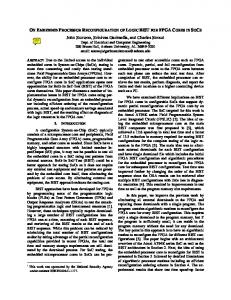
Page 13
Figure 6.2 – Data and control paths of the PH processor
Page 14
7. Programming and debugging tool A simple (programming and) debug tool was created using Visual Basic. The tool, and the process of programming the PH Processor are described in this section. 7.1Overview The debug program executes on a PC and is connected the FPGA board via the UART. The debug control unit was created to interface deeply with the processor core. The transmissions are sent in 64bit data packets with room left for user added debug functions.
Figure 7.0 – PH debug controller data packets
7.2 Compiler Programs are compiled and assembled using a MIPS port of GNU GCC and Binutils. The output of the assembled, compiled and linked process is an ELF 32 format object file, so a program was written to extract the binary data of the text and data segments into two binary files called ‘code.bin’ and ‘data.bin’. 7.3 Programming The two files created from the compilation process above are loaded into the onboard instruction and data RAMs at address zero via the debug program (using the serial port). The instruction memory window is updated with a (disassembled) view of the program loaded into the instruction RAM. The data memory window is updated with the contents of the data RAM. Once loaded the processor must be reset by clicking the reset button before trying to run or single step the code.
Page 15
Figure 7.1 – PH main control debug form
7.4 Control and Data path Debugging By clicking Pipe Control on the above form, opens a new form which allows the loaded program to be single stepped whilst monitoring the instructions data and control paths as they filter through the pipeline stages. The contents of the register file and the data memory are also displayed. This system is useful to check modifications and new instructions added to the processor are operating as intended.
Page 16
Figure 7.2 –PH single step control and data paths debug form
8. Conclusion The PH processor has been tested both by simulations and testing with the debugger running some test programs and a co-operative scheduler with multiple tasks flashing the onboard LEDs. The Core plus the additional Timer, UART, Debugger Control Unit and BL controller utilizes about 79% of the 200K Spartan chip. This includes the large distributed RAM register file implementation, 2KB of instruction RAM and 8KB of data RAM, and has only tested running at a safe 25MHz, however it is thought it can run at least 50MHz (this is still to be tested). The core is simple and well documented as it follows the details described in the Patterson and Hennessy book used in many universities for teaching of computer organization and design and therefore familiar to many students: it provides a good foundation for further research on processor design.
Page 17
References Brej, C. (2002) “A MIPS R3000 microprocessor on an FPGA”, Yellow Star. Manchester University, UK. http://brej.org/yellow_star/ Callahan, T.J. (2002) “Automatic Compilation of C for Hybrid Reconfigurable Architectures”, A dissertation submitted in partial satisfaction of the requirements for the degree of Doctor of Philosophy, University Of California, Berkeley Digilent Inc. (2004) “Spartan 3 Board”, USA. http://www.digilentinc.com/info/S3Board.cfm Fuber, S. (2002) “ARM System-on-Chip Architecture”, 2nd Edition, Addison Wesley, ISBN: 0 20167 519 6
Gray, J. (2000) “Designing a Simple FPGA-Optimized RISC CPU and System-on-a-Chip”, Gray Research LLC, http://www.fpgacpu.org Hammarberg, J. Nadjm-Tehrani, S. (2003) “Development of Safety-Critical Reconfigurable Hardware with Esterel”, Linköping University, Sweden. Hennessy, J. (1982) “Code Generation and Reorganization in the Presence of Pipeline Constraints”, Technical Report No. CSL-TR-81-224, Proceedings of the 9th ACM SIGPLAN-SIGACT symposium on Principles of programming languages. Mexico. Hennessy, J. (1981) “MIPS: a VLSI processor architecture”, Technical Report: CSL-TR-81-223, Stanford University. Jasinski, R. Pedroni, V.A. (2004) “Evaluating Logic Resources Utilization in an FPGA-Based TMR CPU”, Federal Center of Technological Education of Parna, Brazil. Kane, G. and Heinrich, J. (1992) “MIPS RISC Architecture – Introducing the R4000 Technology”, Prentice Hall, New Jersey. Mei, B. Schaumont, P. Vernalde, S. (2000) “A Hardware-Software Partitioning and Scheduling Algorithm for Dynamically Reconfigurable Embedded Systems”, IMEC vzw, 11th ProRISC workshop on Circuits, Systems and Signal Processing Veldhoven, Netherlands. Mei, B. Vernalde, S. Verkest, D. Lauwereins. (2004) “Design methodology for a tightly coupled VLIW/Reconfigurable Matrix Architecture: A Case Study”, IMEC vzw, Proceedings of the Design, Automation and Test in Europe Conference and Exhibition (DATE’04) MIPS Technologies, (2005) “Markets Overview” MIPS Technologies, Inc. http://www.mips.com/content/Markets/Overview/content_html Mwelwa, C., Pont, M.J. and Ward, D. (2004) "Using patterns to support the development and maintenance of software for reliable embedded systems: A case study", Proceedings of the IEE Page 18
/ ACM Postgraduate Seminar on "System-On-Chip Design, Test and Technology", Loughborough, UK, 15 September 2004. Published by IEE. ISBN: 0 86341 460 5 (ISSN: 0537-9989) Mwelwa, C., Pont, M.J. and Ward, D. (2003) "Towards a CASE tool to support the development of reliable embedded systems using design patterns", paper presented at the workshop "Quality of Service in Component-Based Software Engineering", June 20th, 2003, Toulouse, France. Patterson, D.A.. and Hennessy, J. L. (1998), Computer Organization and Design: The Hardware/Software Interface, (Second Edition). Morgan-Kaufmann, San Francisco Patterson, D.A.. and Hennessy, J. L. (2004), “Computer Organization and Design: The Hardware/Software Interface”, (Third Edition). Morgan-Kaufmann, San Francisco Pont, M.J. (2001), "Patterns for time-triggered embedded systems: Building reliable applications with the 8051 family of micro controllers", Addison-Wesley / ACM Press. Pont, M.J. (2003) "Supporting the development of time-triggered co-operatively scheduled (TTCS) embedded software using design patterns", Informatica, 27: 81-88. Pont, M.J. and Banner, M.P. (2004) “Designing embedded systems using patterns: A case study”, Journal of Systems and Software, 71(3): 201-213. Pont, M.J. and Mwelwa, C. (2003) "Developing reliable embedded systems using 8051 and ARM processors: Towards a new pattern language" Paper presented at VikingPLoP 2003 (Bergen, Norway, September 2003). Pont, M.J., Norman, A.J., Mwelwa, C. and Edwards, T. (2003) "Prototyping time-triggered embedded systems using PC hardware”. Paper presented at EuroPLoP 2003 (Germany, June 2003). Singleterry Jr, R.C. Sobieszczanski-Sobieski, J. Brown, S. (2002) “Field-Programmable gate array computer in structural analysis: An Initial Exploration”, NASA Langley Research Center. Virginia. Sinha, S.K. Kamarchik, P.M. Goldstein, S.C. (2000) “Tuneable Fault Tolerance for Runtime Reconfigurable Architectures”, Carnegie Mellon University, Pittsburgh. Wolf, T. Franklin, M. (2000) “Commbench – A Telecommunications Benchmark For Network Processors”, In IEEE intl. Symp. On Performance Analysis of Systems and Software
Page 19
9. Appendix 9.1Instructions Set of PH Processor
Instructions taken from MIPS 1 ISA, (Kane and Heinrich, 1992)
a) Non R-type instructions
Mnemonic
Name
Opcode
LW
Load Word
100011
SW
Store Word
101011
LB
Load Byte
100000
LBU
Load Byte Unsigned
100100
LH
Load Halfword
100001
LHU
Load Halfword Unsigned
100101
SB
Store Byte
101000
SH
Store Halfword
101001
BEQ
Branch On Equal
000100
BNE
Branch On Not Equal
000101
ADDI
Add Immediate
001000
ADDIU
Add Immediate Unsigned
001001
ANDI
And Immediate
001100
J
Jump
000010
JAL
Jump And Link
000011
LUI
Load Upper Immediate
001111
ORI
Or Immediate
001101
XORI
Exclusive Or Immediate
001110
SLTI
Set Less Than Immediate
001010
SLTIU
Set Less Than Immediate Unsigned
001011
Page 20
b) R TYPE
Mnemonic
Name
Funct
JR
Jump Register
001000
JALR
Jump And Link Register
001001
ADD
Add
100000
ADDU
Add Unsigned
100001
SUB
Subtract
100010
SUBU
Subtract Unsigned
100011
AND
And
100100
OR
Or
100101
SLT
Set Less Than
101010
SLTU
Set Less Than Unsigned
101011
NOR
Nor
100111
XOR
Exclusive Or
100110
SLL
Shift Left Logical
000000
SLLV
Shift Left Logical Variable
000100
SRA
Shift Right Arithmetic
000011
SRAV
Shift Right Arithmetic Variable
000111
SRL
Shift Right Logical
000010
SRLV
Shift Right Logical Variable
000110
c) Special Coprocessor instructions
Mnemonic MTC0 MFC0
Name Move To System Control Coprocessor Move From System Control Coprocessor
Opcode
MT/MF
010000
00100
010000
00000
Page 21