RAY J. KING, SENIOR MEMBER, IEEE, DAVID v . THIEL, MEMBER, IEEE, AND KWANG s. PARK, MEMBER, IEEE. Abstract--A thin artificial dielectric layer ...
IEEE TRANSACTIONS ANTENNAS ONAND
47 1
PROPAGATION, VOL. AP-31, NO. 3, MAY 1983
The Synthesis of Surface Reactance Using an Artificial Dielectric RAY J.
K I N G , SENIOR MEMBER, IEEE, DAVID v .
THIEL,
MEMBER,IEEE,AND
KWANG
s. PARK, MEMBER, IEEE
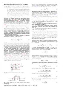
ical realization should, of course, correspond as closely as possible to the assumed mathematical model. Examples where idealized mathematical models are solved using assumed profiles of surface reactance over a plane are shown in [2] and [3], but the equally important question regarding the physical realization of the reactances is not addressed. The purpose of this paper is to describe how any value of surface reactance Z , = j X , can be synthesized which is 1) independent of the angle of incidence for plane waves, 2) prohibits ducting of energy beneath the surface, and3) is a function only of the local structure beneath the surface, e.g., the refractive index and I. INTRODUCTION nonhomogenieties encountered for a wave propagating normal to HEN FORMULATING boundary value problems it Is often the surface. The angular independenceproperty 1) is useful when repreexpedient to assume that the boundary conditions at a surface can be represented by a prescribed distribution of the surface senting source or scattered fields as angular spectrums of plane impedance 2, over the surface. While such assumptions may ease waves. The nonducting property 2 ) does not permitleakage of enthe analytical/numerical calculations and their interpretation, one ergy from within the surface to the outer region(e.g., air), alshould be aware of the practicaldifficulties in physically realizing though radiation and scattering from changes in X, are possible. the assumed surface impedance and recognize pitfalls in ascribing Property 3) permits the synthesis ofreactances X,which can vary impedance values to general surfaces. This is particularly import- arbitrarily in anydirectiontangenttothesurface,including ant when a surface can support multiple wave species, as in the slowly varying curved surfaces. This feature makes the technique attractive for aerodynamic applications. case of multilayeredmedia [ I ] . Such species may exist in the To theseends, we consider thetheory, design? andexperivicinity of a source since the source emits a wide angular specreactances synthesized using trum of plane waves, or where scattering occurs in ducts or at mental verification of surface grounded uniaxially anisotropic slabs. These slabs have the form curved portions of the surface. To offer some examples, the surface impedance can vary with of a “fakir’s bed of nails,” consisting of a rectangular array of the angle of incidence for plane waves, even if the medium de- short conducting pins of height t oriented normal to a conducting scribed by 2, is plane andhomogeneous. This angular depen- ground plane(Fig. 1). With proper choicesin the diameter and dence disappears as the index of refraction becomes large, such as spacing of the pins, lateral (x or y ) propagation within the slab can be made to be below cutoff permitting only vertical ( z ) propthe case of the earth at low frequencies. In multilayered media containing ducts, trapping of energy can occur resulting in mul- agation within the slab. Simultaneously, the vertical wavenumber within the slab k,, becomes essentially independent of the lateral tiple surface and leaky wave modes, especiallyif the ducts are nonuniform or contain nonhomogeneties [ 11 . In general, the sur- wavenumber k, which is the same for the fields in the air and in face impedances differ for each mode within each species. so the theslab.The reactanceseen atthesurface is thereforeonlya use of a surface impedance to describe the total field becomes function of the slab thickness and kil. which in turn is only a functionofthe dielectric constantoftheembeddingmedium. ambiguous. Thus care must be exercised when using the surface impedance Sinceenergy flow within the slab is not possible, the localpin height and/or dielectric constant can be varied to synthesize nonto set up a mathematical model of a particular physical problem. uniform reactances. It should also be apparent that the sameconConversely after having obtainedasolutionfor anidealized mathematical model using an assumed surface impedance distri- clusions are reached if the slab is gradually curved. Kay [4] apparently was the first to measure the reactance of a bution,one is faced withthe task ofactuallyconstructinga fakir’s bed over 20 years ago. He recognized that a true reactance physicalrealizationin the laboratory, and perhaps ultimately a manufacturered end product. In this synthesis problem, the phys- surface should have a reactance which is independent of the incidence angle, but the surfaces which were constructed and tested showed some slight angular dependence for reasons which will be klanuscript received June 2,1981; revised November 8, 1982. This apparentlater.Querido [5] conductedexperiments on square work was supported in part by the University of Wisconsin Engineering Experiment Station and Research Committee. andcircularpinstructureshadngoftheorderof 50 percent R. J. King is with the Lauwence Livermore National Laboratory, Livermetal and developedanempiricalexpression for predicting the more, CA 94550, on leave from the Electrical Engineering Department, reactance. Up to this time, the theory and experimental results University of LVisconsin, Madison, W . have been too inconclusive to explain completely how the strucD. V. Thiel is with the School of Science, Griffith University, Nathon, ture works and how optimal designs can be made. A preliminary 441 11, Australia. K. S. Park is with Bcll Laboratories, IIolmdel, NJ 07733. r e p o r t of this work was recently published [ 6 ] . Abstract--A thin artificial dielectric layer consisting of a rectangular array of closely spaced,thin conductive cylinders (pins), was constructed above a perfectly conducting ground plane. The reactance of the surface wasmeasuredat 4.8 GHz for a varietyofpinheightsanddielectric embedding material by measuring the height-gain profile of a transverse magnetic (TM) surface wave launched across it. Design equations using the theories of artifical dielectrics and propagation in anisotropic media are given. These can be used to predict the surface reactance providing a correction factor accounting for fringing fields at the tops of the pins is included.Usinganembedding dielectrictendstoreducethisfringing effect.
w
0018-926X/83/0500~471$01.000 1983 IEEE
.
.. _
472
IEEE TRANSACTIONS ON ANTENNAS AND PROPAGATION, VOL. AP-31, NO. 3, MAY 1 9 8 3
Thus for 0 < 8 < 0, (or 0 1. Conversely the y-directed H-fieldlines tend to diverge away from the pins, so p,,/pd < 1 (see Fig. I(b)). Determining k,, : When a two-dimensional transverse magnetic (TMX) wave is propagating in air (z >0) over an anisotropic medium (z < 0) having its axes of anisotropy in t h e x , y , and z-directions, the z-component of the wavenumber in the anisotropic medium is [ l o ]
where k, is the x-directed wavenumber of the incident wave in the air and is the same in the anisotropic medium.In view of the preceeding definitions, ( 6 ) can be simplified to 2
k,,
1/2
=(kg+$)
assuming the medium is below cutoff so that p is real. It is important to note that if p 2 > 1, k,, becomes independent of the longitudinal wavenumber k , and hence independent of the wave
473
KING e t al.: SYNTHESIS O F SURFACE REACTANCE
species in the air. As applied to a half-space of an array of z-directedconducting cylinders, and also to the pin-bed structure shown in Fig. 1 this means that unattenuated propagation is only permitted in thef z-direction along theaxes of the conductors. For example, if the incident T M x field in the air is a uniform plane wave, then k, = k, sin p! where (1 is the angle of incidence measured from the surface normal. For a trapped surface wave grazing along the surface, as might exist over a pin-bed slab k, = ko (1 X 2 ) l l 2 where X (=Xs/qo) is the surface reactance normalized by qo = 1 2 0 ~ In . eithercase, (7) showsthatifthe medium is well below cutoff such that p 2 5 1, then k,, s kd, i.e., k,, is independent of q for a plane wave and independent of X for a surface wave, The Surface Reactance: We are now in a position to determine X for the structure shown inFig. 1 . The magnetic field of a twodimensional TMX trapped surface wave has the form ~
+
exp [-(m + jk,x)] , for z
> tl
and cos (k, ,z)e-jkXX,
for o < z < t ,
where k, = ko (1 4- X2)1'2,u = k,X, and tl is the apparent thickness of the artificial dielectric. Applying the boundary conditions EXo/Hy0 = E,, /Hy = -jqoX at z = t l , we obtain
This same form is also obtained for a plane wave at oblique incidence. For a given pin configuration, calculation of X ( t , ) is simple if p 2 S= 1 in (7). It is also easy to calculate ~ ( p t ,l ) for an incident plane wave using k, = k, sin p in (7), even if p is not large. The situation is more complicated if p is not large in the case of a surface wave. The difficulty arises from the fact k,, in (7) is a function of X . Solving (7) for X and equating the result to (8) gives the transcendental equation XkOtl
= [(kz 1 t l p ) 2
2 2 2 112 - (kiikdp It11
-- k, 1 t l tan (kz 1 t l ) .
(9)
Ex
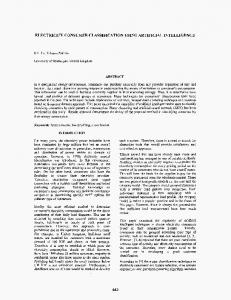
Considering u(=k, t l ) as theindependent variable, Xkotl is plotted in Fig. 2 versus the two equalities in (9) for E , = 1.081 kd = k, (air dielectric), t , = 0.1 &, and several values o f p . The first equality is a hyperbola, Xkot, = [(up)2- c 2 ] 1 / 2 where ~
c = (ki
+ kip2)'/2tl
(10)
and the second qualityis of the form E;'U tan u . Clearly, an infinite number of solutions for X are obtained, as was predicted by Bolljahn [ l l ] 20 yearsago.Heproved that a finite group of trapped surfacewaves could not be supported bya plane surface through which there is no energy transport. However, from apracticalviewpoint the surface can be designed so thatonlyoneortwomodesaredominant.Forexample:the smallest positive value of X gives a surface wave mode which is easiest to excite andto measure experimentally.It has been known for some time that for a given X , there exists an optimum nonzerosource height wherethesurface wave launching e f f ciency is maximum [12], [13]. As one might expect, this optimum height decreases with increasing X because the surface wave field is trapped closer to the surface. Thus, for a mode haling very large X , little power would be coupled into that mode by a
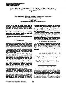
source which is situated t o launch maximum power into a mode having much smaller X value. For the pin structure where multiple solutions for X are possible, it is therefore desirable to choose the pin diameter and electrical spacing 0 so t h a t p is sufficiently large t o make X large for all but the lowest mode. For the dimensions shown in Fig. 1, p = 7.30 at 4.8 GHz using air as the dielectric, Then, from Fig. 2 , k,X(')t, 0.436 or$') = 0.694 for the lowest mode (compared t o X = 0.672 using (8) with k z l s k,). Forthesecondmode koX(2)tl = 9.36or = 14.9. Excitation of the second and higher modes would therefore be unlikely. When the electricalspacing 0 (=kda) increases, p decreases. For a given tl /A,,, the major effect ofreducing p is to reduce the reactance of the higher modes noticeably while that of the lowest mode is increased slightly. As p continues to decrease, a point is reached where $*) is nearly the same as $ I ) (e.g., f o r p S 2 in Fig. 2); in this case, both modes would be excited with comparableefficiencies.Moreoversmall imperfections in the structure would cause coupling between the modes and the reactances for both modes would be highly unstable. Finally, i f p decreases still more, the lowest solution skips from the first to the second tangent curve (e.g., for p = 1 S),giving a considerably larger reactance. A similar family of hyperbolas can be drawnusing t , /Ao as the parameter for a constant value of p . The major effect of increasing t , / h , is to shiftthehyperbolastothe right such that the intercept is k z l t l = c/p where c is given by (10). 111. EXPERIMENTAL RESULTS An open-ended C-band waveguide was laid flat on the topof a pin bed structure (Fig. 1 ) having dimensions 33 cm X 55 cm (51 A,, X 8.8 A,) as shown in Fig. 3. A .1.2 cm long z-directed dipole,
.~
474
IEEE TRANSACTIONS ON ANTENNAS AND PROPAGATION, VOL. AP-31, NO. 3 , MAY 1983
0-
-2-
-
-4
0-
Iu
.
-2-
w -
-
w -4-p
Fig. 3.
Experimental configuration for measuring E , versus height h.
2
0-
a
.
-I
;- 2 center loaded with a p-i-n diode and suspended by nylon lines at height h was electrically modulated at 10 kHz via AWG no. 26 enameled leads oriented parallel to themagnetic field vector. This created a modulated scattered signal proportional to Ei(h). The amplitude and phase of the backscattered signal were then measured using a homodyne detection system, as described by King
1 1 . .
0
1
0
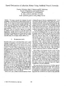
1141. as a The relative signal amplitude and phaseweremeasured function of h for four different pin heights and four different embedding media. Using alinear regression program, the mean slope S (in dB/cm) of I E,@) I was calculated and used to determine the reactance X = S/(8 .686 ko).Results for the smallest pin height o f t = 0.25 cm (0.04 &) are plotted in Figs. 4(a) and 4(b), taken at a distance of 41.5 cm (6.64 io)from the source. The linear portions of the curves are clearly evident. Deviations for linearity at small heights are the result of changes in the scattering diode's self-impedance in the proximity of the surface. Deviations from linearity atlarge heights are the result of interference by direct radiation from the source and scattering from the end a n d edges of the structure. The phase shows little variation with height above about 0.2 b:giving strong evidence that a true surface wave is dominant in this region. The experimentally determined X values for four different pin heights and four different dielectrics are presented in Table I . An increase in pin height and/or dielectric constant of the embedding medium results in an increase in the surface reactance, but these values differ somewhat from the results predicted by (8). We conclude that the effective thickness of the artificial dielectric tl is less than the actual height of the pins t , due to fringing at the tops of the pins. These fringing fields have the effect of adding capacitive loading to what is basically an inductive piece oftransmission line. This reduces the effective depthofthe structure. Such an effect shouldbeindependent ofpinheight butdependentonthe dielectric constant of theembedding medium. In fact, one of thechief reasons for testing several thicknesses and dielectric constants was to check this hypothesis. Inverting (8),
which was used to calculate the apparent thickness t l from the measured X values. Included in Table I are values of Af/ho = (t - tl)/ho. Note that At is positive, indicating that the slab appears to be thinner than the actual pin structure as expected. Such a phenomenon is also predicted in the case of TMx surface waves propagating normal to the conductingaxes of an array of thin conducting strips oriented normal to a ground plane [9]. In this case, fringing between the tops of the strips is expected to
2
02
I
3
,
4
0.4
PROBE
(a)
5
~~..ooo.ooD.ooQ..o
)
6
116 0.8 HEIGHT
C
m
LOA0
O L
0
1 .
2 l 02
.
3 I 0.4
4 ,
PROBE
5 : 0.6
.
6 , 0.8
c ,
m l 1.0
A.
HEIGHT
(b)
Fig. 4 . Typicalprofiles of the magnitude (a) andrelativephase (%)of E,(h) for various ~d using the slab design shown in Fig. 1. Frequency = 4.8 GHz, r = 0.04 ho, and distance from source = 6.64 ho.
give At=-
a In 2
4G
for dielectric-fded corrugations, where a is the spacing between thestrips. While the pin structure is two-ratherthan one-dimensional, it is encouraging to note that the At calculated using (12) is quite similar to the meanvalue of that determined experimentally using thepinstructure, especiaUy when ed > 1 (see Table I). A corresponding two-dimensional analysis is required to determine the exact solution. Using (9), we can show that for large p the reactance of the lowestmode is proportional to tz;i2tl, i.e., 3') is less dependent on ed than on the slab thickness. The data in Table I confirm this relationship. The major effectof increasing f d is that At is substantially reduced, e.g., for t = 0.53 cm. the meanvalue of At is 29 percent o f t for Ed = 1, compared t o 15 percent for ed = 1.5, I 3 percentfor ed = 2.5 and 11 percentfor ed = 3. Thus, by making Ed > 1.5 the apparent thickness tl = t - At can be calculated with reasonable accuracy using (12). In turn, can be calculated more precisely than in the case where f d = 1. Moreover, in a practical sense it is usually preferable to frll the space between the pins with a solid dielectric for strength and aerodynamic reasons, and to avoid accumuIated water or other foreign matter. Kay 141 observed some angular dependence of X(0) on a pinbed structurewhere a = b = 0 2 and d = 0.24 b. Since the condition d Q b i s minimally satisfied, (1) and ( 2 ) are not expected to give precise results. Nevertheless, the use of (2) shows that the frequency Kay used is only about half of the cutoff frequency.Consequently p z is not large,making k,, in (6) and hence X in (8) dependent of the incidence angle 0 . Similar experiments on a corrugatedmetalstructure showed less angular dependence, presumablybecause thecorrugations werespaced nearly half as far apart as were the pins. Querido [5] made relative velocity c/v [=(I + X2)1/2]meas-
47 5
KING et at.: SYNTHESIS O F SURFACE REACTANCE TABLE I EXPERIMENTALLY OBTAINED VALUES O F AND At/Ao USING FOUR VALUES O F Ed AND FOUR PIN HEIGHTS
x
urements on square andcircular cylindrical post structures.Based onan emprically extendedtheoryforpropagation over corrugated metal surfaces, the best fit with the experimental data was obtained by taking k,, = 1.05 kd. The factor of 1.05 supposedly accounted for the fact that €,/Ed is slightly greater than unity because of the metal pins. However, no account was made for the fact that fly/,& < 1, that k,, is a function ofk, andp (see (7)), or that fringing nccurs a t the t o p s of the cylinders. Itappears that the combined effect of all of these factors was included in the empirical constant 1.05. Also, a weighmg factor F equal to the cross-sectional area of the metal per unit area of surface was used in place of the factor kz,/(e,ko) in (8). In Querido’s structures, the pins constituted 50 percent of the surface area so (1) and the rest of the theory presented here cannot be checked against his results.
IV. DISCUSSION From the theory in Section I1 it is apparent that if a = b the surface reactance is the same for propagation in t h e x o r ydirections. More generally, X is isotropic in any direction tangent t o the surface if the ZocaE value o f p 2 S 1 in that direction. This permits some degree of variance in the density and diameter of the pins, and eases construction constraints.As noted earlier, the condition p z % 1 assures the designer that propagation inside the slab is well below cutoff. Then X is almost totally a function of the localslab thicknessandembeddingmedium,with a slight dependence on the local pindensityanddiameterthrough e, as given in (5). The effective pin height t l , is equal to the true height t , less a small correction AI as given approximately by (12) which accounts for the capacitive fringing of the electric field in the air above the pins. These properties permit variable reactance X(x, y ) profiles to be synthesized in two dimensions, wherex andy are the local coordinates tangent to the surface. This amounts t o prescribing desired boundary conditions, and implies control over the guiding, radiating and scattering properties of surfaces.Field distributions on the surface can then be prescribed, as can radiation patterns. For example, nonuniform reactance surfaces synthesized in this manner would be useful in the design of the main body, reflectionless tapersand reflectionless terminationson guided wave structures [3], [I51 and in the design ofabsorbers andreflectors. The reactance can also be varied periodically to induce radiation in preferred directions [2] .Plane pin-bed surfaces on which thereactance changes abruptly have recentlybeensynthesized
and the behavior of the fields near the surface have been studied experimentally [ 161 . Because (9) has multiple solutions as shown in Fig. 2, some consideration should be given to the type of sourceused to excite only the lowest mode. Excitation of the higher modes can also be avoided by choosing the dimensions so as to make p large. Although probably obvious from Fig. 2, note that for sufficiently large t l and p , it is possible to achievc a wide range of negative (capacitive) reactances as the first solution. At the same time, the second solution can be a very large inductive reactance, the mode of which would be difficult to excite.This may be useful in the design of horns and closed waveguides, as is now done using corrugated metal surfaces. The advantage is that capacitive surfaces repel TMX fields away from the metal, thereby reducing the losses. Such capacitive surfaces may also be of value for terminating an inductive surface wave structure so as to cause the radiation field to decrease much more rapidly along the surface thanwhenthestructure is terminatedby a conductingplane [15]. As in the case of inductive surfaces, a nonuniform capacitive reactance profde can be synthesized. Finally, it is also feasible to introduce a defined loss component into the surface impedance (Z, = R , + jX,) by mixinga lossy material with the embedding dielectric. This would be useful formodeling groundwave propagation over a nonhomogeneous flat or curved earth [ 161. ACKNOWLEDGMENT Our appreciation goes t o Dr. C. J. Teng who constructed the pin beds, andW. S. Park who assisted in these experiments. REFERENCES S. J . Maurer and L. B. Felsen, “Ray methods for trapped and slightly leakymodes in multilayeredormultiwave regions,” IEEE Trans. MicrowaveTheoryTech., vol. MTT-18, no. 9, pp. 584-595, Sept. 1970.
S. H. Cho and R . J . King, “Radiationfromfinitesinusoidally modulatedreactancesurfaces ( S M R S ) , ” Radio Sci., vol. 11, no. 6 , pp. 561-570, June 1976. -, “Numericalsolution of nonuniformsurfacewaveantennas,” IEEE Trans.AntennasPropagat.. vol. AP-24, no. 4, pp. 483-490, July 1976. A. F. Kay, “Applied problems in electromagnetic theory,” Tech. Res. Group, contract AF 19(604)-3476, AD 261 286, Apr. 1961. H . B. Querido, in C. H. Walter, TravellingWaveAntennas. New York: Dover, 1965, p. 266. R. J. King and K . S. Park, “Synthesis of surface reactances using a grounded pin bed structure,” Elecrron. Letr., vol. 17, pp. 52-53, Jan. 8, 1981. J. Brown, “Artificial dielectrics,” Prog.Dielect., vol. 2 , pp. 195225, 1960.
47 6
TRANSACTIONS IEEE
J. Brown,“Artificialdielectricshavingrefractiveindiceslessthan unity,” Proc. Znst. Elec. Eng.. vol. 100, pt, IV, pp. 51-62, 1953. R. E. Collin, Field Theory of Guided Waves. New York:McGrawHill, 1960, p. 467. R. I. King, “Ground wave propagation over horizontally layered anisotropic media,” Appl. Phys., vol. 5 , pp. 187-196, 1974. J. T.Bolljahn,“Synthesis of modulatedcorrugatedsurface wave structures,” IRE Trans. Antennas Propagat., vol. AP-9, no. 3, pp. 236-241, May 1961. D. HemmendingerandF. J. Zucker, “A forgottentheorem and its application to surface wave excitation,”ZEEE Trans. Antennas Propagat., vol. AP-18, no. 1, pp. 132-133, Jan. 1970. S . H. Cho, “Electromagnetic wave propagation over nonuniform surface impedance planes,” Ph.D. dissertation, Univ. Wisconsin, Madison, WI, 1975. R. J . King, Microwave Homodyne Systems. Peter Peregrimus, 1978, p. 148. K. S . Park, Reflection Transmission and radiation of anEM surface wave incicent on a transition of surface reactance, Ph.D. dissertation, Univ. Wisconsin, Madison, WI, 1980. R. J. King,“Physicalmodeling of EM wavepropagationoverthe earth,” Radio Sci., vol. 17, no. 5 , pp. 1103-1116, Sept.-Oct. 1982.
ON ANTENNAS AND PROPAGATION, VOL. AP-31, NO. 3, MAY 1983 tems, traveling wave propagation over nonuniform surfaces, elecbomagnetic modeling,andmicrowavenondesmctive evaluation. Hehas lecturedand consulted at various universities, government laboratories, and commercial industries in Europe, England, New Zealand, and the United States. Dr. King is a member of Sigma Xi, Sigma Phi Delta, Iota Tau Kappa, the IEEEMicrowaveTheoryandTechniquesandAntennas and Propagation Societies, the American Societies for Engineering Education, the University Professors for Academic Order, and USNC/URSI Commissions B and F.
David V. Thiel (”81) received the B.Sc. (Hons) degree from the Universityof Adelaide, Australia, in 1971 and the M.Sc. and Ph.D. degrees in radio physics from James Cook University, Townsville, Australia. He is currently a Senior Teaching Fellow in the School of Science at Griffith University, Nathan, Australia. In 1981 he was a Visiting Fellow at the Department of Electrical and Computer Engineering at the University of Wisconsin, Madison. His currentresearchinterestsrelatetosurface impedance measurements over nonuniform media. Dr. Thiel is a senior member of the Institution of Radio and Electronics of the Australian Instituteof Physics. Engineers of Australia, and a member
KrangS. Park (S’73-M’744’78-M’80) was born in Kaecheon, Pyeong-Nam, Korea, on July 17, 1948. He received the B.S. and M.S. degrees 1970 and fromthe Seoul NationalUniversityin 1974, respectively, and the Ph.D. degree from the University of Wisconsin, Madison, in 1980. From 1970 to 1972, he taught as an officer at the Signal School of the Korean Army. From 1974 to 1975, he was an engineer at the Korean Instituteof Science and Technology.From 1981 to 1982, he was a Research Associate in the Propagation Laboratory in the University of Wisconsin. He is currently a Member of Technical Staff in the Satellite Technology Groupat Bell Laboratories,Holmdel,NJ.Hisareasofresearchincludeelectromagnetic wave propagation, antennas, and microwave devices. Dr. Park is a member of Sigma XI and Phi Kappa Phi.
>