Speed Estimation of Induction Motor Using Artificial Neural Networks. Prashant Mehrotra, John E. Quaicoe and R. Venkatesan. Faculty of Engineering and ...
Speed Estimation of Induction Motor Using Artificial Neural Networks Prashant Mehrotra, John E. Quaicoe and R. Venkatesan Faculty of Engineering and Applied Science Memorial University of Newfoundland St. John’s, NFLD, A1B 3x5, CANADA email: { prashant ,jquaicoe,venky } @engr.mun.ca
-
Abstract This paper proposes two techniques for speed estimation of induction motors using artificial neural networks. The techniques are based on speed expressions obtained from the induction motor dynamic equations. Two of the equations obtained have singularities, and hence direct speed estimation from these is not possible. The paper proposes a scheme using two ANNs to recover the speed from these two equations. However, it is possible to combine these two equations in a way that removes the singularities. Another method, based on this equation, is presented for obtaining the speed directly from the output of an ANN. These methods are general and easily implementable using commercially available ANN devices.
I.
INTRODUCTION
widespread usage in function approximation [5]. It has been shown that theoretically a three layer ANN can a p proximate arbitrarily closely, any nonlinear function, provided the function is continuous and non-singular [6].This property has been exploited by a few researchers working in the induction motor drives area. Toh et al. [7]developed a flux estimator for use in vector controlled induction motor drives using ANNs. Two ANNs are used in this method - one for obtaining the magnitude of the rotor flux and the other for obtaining the sine of its space phase angle. In another study by S i m k and Bose [8], four feedback signals for a direct vector controlled induction motor drive have been estimated using ANNs. A small sized ANN is used in this work to estimate the rotor flux magnitude, the electromagnetic torque and the sine and cosine of the rotor flux angle. Wishart and Harley [9] used the basic principles outlined in [5] to identify and control induction motors. They performed closed loop speed control using speed feedback. Although the scheme gives excellent performance comparable to the vector control scheme, the simulation study shows that there is a risk of saturation since there is no control over the flux. Also, the scheme utilizes a speed sensor which is considered undesirable.
Induction motor speed control has always posed a great challenge t o researchers in the drives area because of the non-linear dynamic nature of the induction motor. In addition many of its parameters vary with time and operating condition. Because of this, its applications in the area of speed control have traditionally been limited. The advent of Field Oriented Control or Vector Control [2] was a major Even though a lot of research has been carried out into breakthrough in the area of induction motor control. With developing ANN techniques to control induction motors this technique, the induction motor is transformed, for the and estimate some of the parameters like flux and torque, purpose of control, into a separately excited DC motor. not much work has gone into speed estimation of induction Independent control of flux and torque is possible, resultmotors using ANNs. In a recent work, Ben-Brahim [lo] has ing in servo like performance. Although, vector controlled used linear ANN technique to estimate induction motor drives are quite popular, they suffer from some drawbacks speed. Though the technique gives a fairly good estimate like incorrect measurement of flux at low speeds, lack of of the speed, it lies more in the realm of adaptive control robustness against parameter variation and so on. A mathan neural networks. The speed value is not obtained at jor drawback of a lot of such schemes is that they require the output. Instead, the magnitude of one of the weights a speed sensor. Speed sensors cannot be mounted in some corresponds to the speed magnitude. cases, such as motor drives in hostile environments, high speed motor drives and drilling applications. Also, they The main objective of this work is to develop a general are usually expensive, bulky and reduce the advantage of purpose induction motor speed estimator based on the dyan induction motor drive. Because of these drawbacks re- namic equations of the induction motor. Two techniques searchers have put in a lot of effort in developing speed are presented for estimating the speed of an induction mosensorless induction motor drives [3], [4]. tor using ANNs. As opposed to some methods for estimatIn the recent past, artificial neural networks have found ing speed, these schemes do not depend on any particular
0-7803-2775-6/96 $4.000 1996 I E E E
881
control technique like vector control or some form of a d a p tive control. Instead, these schemes can be used quite independently of the control algorithm, like a shaft encoder. Standard multilayer feedforward networks and the popular backpropagotion algorithm are used to recover the speed. This paper is structured as follows. The induction m e tor equations are presented in section I1 and expressions for the rotor speed are derived from these. A discussion of speed estimation is presented in section 111. Section A outlines speed recovery using functions having singularities and section B outlines the same for a function without singularities. Simulation results for these two cases are also presented in these two subsections. Some concluding remarks are presented in section IV.
wr
-
2 dim,
+ &'
&L$i,q
[U dt
SvZqdt
+ LrvZq]
(8) 4-Lr f , vvzq= K q - R 8 & , and u2 = L L -
U2isd
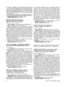
where, V z d = V S d - R , i 8 d L r L , . The induction motor speed can be recovered from either of (7) or (8). However, both these equations have singularities for regular induction motor operation. This can be seen by plotting the numerator and denominator of either equation. Figure 1 shows a plot of the numerator and denominator for (7).
4,
Numerator Function I
I
0.16
0.17
I
1
0.19
0.2
11. INDUCTION MOTOREQUATIONS The d-q axis dynamic equations for the squirrel cage induction motor are given by [l]
V = AI
(1)
where,
v =[
A=
and,
i
K d
Rs + P A , PLm -wrLm O
Vsq
0
Rs+pLs wr Lm
0
0
-4
0.15
0.01 r
1'
0.18
Denominator Function I
I
I
(2)
PLm 0 R, PLr
+
PLm
0 wrLr
+
R,pLmPLr
1
(3)
I'
I = [ i s d i,, i,d i,, (4) In the above equations, subscript s denotes stator quantities, r denotes rotor quantities, q and d refer to the quadrature and direct axis quantities respectively and L , is the magnetizing inductance. We can see that in (l),if the stator voltages and stator currents are known along with the machine parameters, we have only 3 unknowns, viz. W r , ird and i,. We can thus solve for wr in terms of the stator quantities only. First, we obtain the rotor currents as functions of the stator quantities and wrr from the first two rows of (l),since the rotor currents are not accessible in a squirrel cage induction motor. The expressions for i r d and i, are obtained as ird
=
-[/(Kd
1 Lrn
- &isd)dt
irq
=
-[J(%q
1 L,
-~sisq)dt ~aiaq]
- Lsisd]
(5)
-
(6)
We can substitute (5) and (6) in the last two rows of (1) and obtain two expressions for the rotor speed wt as
882
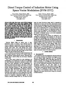
Time (sec) Figure 1: Numerator and denominator functions in the speed expression of equation (7) It can be seen from Fig. 1 that both waveforms are in phase, resulting in simultaneous zero-crossings, and hence, singular points. Equation (8) also produces a similar plot, but both the waveforms are phase shifted by goo. A comparison of the numerators and denominators of equations (7) and (8) is shown in Fig. 2. From Fig. 2 we can see that both the numerator and denominator for equation (8) lead those for equation (7) by 90°. This suggests that we can treat them like d and q components of a vector or space phasor quantity. Thus equations (7)and (8) can be combined by treating one as the direct axis component and the other as the quadrature axis component. The final expression for speed thus obtained is given by
~
Numerator Functions
4,
1
I
-4 0.15
0.16
0.17
I
0.18
I
1
0.19
0.2
This problem does not exist in (9), but it is a more complex function compared to the other two. This paper proposes two types of schemes -one for the singular functions given in (7) and (8),and the other for the function given in (9). The parameters of the induction motor used in the methods described below are given in the Appendix. The basic problem in training an ANN to recognize induction motor speed is that the functional relationship between the speed and the stator parameters is quite complex with the result that the number of training vectors required is very large. Thus, it becomes difficult for the commercially available ANN softwares to handle the large data files involved. Also, the training times involved on a PC become quite substantial. To circumvent the problems of large data files and substantial training times, the whole drive system with the ANN was simulated in C++ on a SUN SPARGlO workstation. A multilayer backpropagation neural network was used in the simulation, and the sigmoid function was used as the non-linear element. The structure of the ANN can be defined in an external parameter file. The generalized delta rule given by,
Time (sec) Denominator Functions
0.02 I
-0.02
'
15
I
I
0.16
0.17
I
I
I
I
0.18
I
I
0.19
I
I
+
0.2
Time (sec) Figure 2: Comparison of the two speed expressions where is and vs represent the stator current vector and stator voltage vector respectively. These are given by
Awjj(n) = aAwji(n - 1) $ j ( n ) y i ( n ) (12) was used for updating the weights, and both the learning rate (7) and the momentum parameter (a)can be defined in the external parameter file. The training vectors were generated online, obviating any need for storing training data on the disk.
A. Method 1: Using Singular Functions
Note that the R.H.S. of equation (9) is complex and the speed would be given as the modulus of the equation. It is possible to obtain the speed of an induction motor in another fashion by solving the induction motor dynamic equations simultaneously to obtain wr and &. However, both the numerator and denominator in the expression obtained will go to zero if sinusoidal currents and voltages are assumed. On the other hand, non-zero values are obtained for non-sinusoidal currents and voltages, as in inverter operation [ll]. Thus, this technique is limited in its usefulness and is not very general.
111. SPEED ESTIMATION One of the necessary conditions for an ANN to approximate a function is that the function be square integrable in the n-dimensional unit hypercube [12]. This condition is obviously not satisfied by either (7) or (8) because both equations have singularities. Thus, it would be futile to expect to train the ANN to recognize speed using the quantities on the right hand side of either of these equations.
883
The basic idea in this method is to partition the main function having singularities (or poles) into smaller functions which do not have any singularities, and to train small ANNs to identify these smaller functions. The desired output can be obtained from the outputs of these ANNs by avoiding the singular points or poles of the main function. In this case, one of the simplest ways to partition the functions is to consider their numerators and denominators separately. The numerators and denominators of equations (7) and (8), can be expressed respectively as
ANNs can be trained to approximate either N1 and D1 (equation 7 ) or N2 and Da (equation 8). The output of these ANNs can then be passed through a filter which performs the required division at points where both the numerator and denominator are non zero. A block diagram of the speed recovery scheme is shown in Fig. 3.
2000 I
Load Step (10%-150%) I
I
I
I
0.5
1
1
I 1.5
Time(sec) Figure 4: Actual and ANN Recovered Speed (Method 1) determined. Thus this technique would require very high performance A/D converters and dedicated ANN hardware to implement it in real time. Another problem with this technique is that it requires some form of a zero-crossing filter. This would pose a problem if this scheme has to be implemented on an ANN chip. Figure 3: Block Diagram of ANN Speed Recovery (Method 1)
B. Method 2: Using Non-Singular Function
In the simulation study performed, both the ANNs have 2 hidden layers each. Inputs given to the numerator ANN were i b q ( k ) , v s q ( k ) ,Jvsqdt and Sisq&. Inputs given to the denominator ANN were v , d ( k ) , Jv,ddt and J i s d d t . Training was initiated by giving random inputs to the ANNs. The same random inputs were also given to the numerator and denominator functions and the desired outputs for training the ANNs was obtained from these functions. The learning rate parameter was maintained at 0.25 and the value of the momentum parameter was fixed at 0.2 throughout the training. After giving 5 million (5 x lo6) vectors of random inputs, 1 million vectors of direct online start with step variations in load were given. After this ofline training, the ANNs were able to mimic the numerator and denominator functions quite accurately. For the actual speed recovery, a positive-negative peak detector was used as the filter in the block diagram. This detects the positive and negative peaks of the sinusoidal outputs of the two ANNs. The actual and ANN recovered speeds for direct-on-line start and step change in load torque are shown in Fig. 4. As can be seen from Fig. 4, the performance of the speed estimator is fairly accurate. However, since this scheme requires the computation of the numerator and denominator functions, a very small sampling time is required even though the speed feedback need not be computed very frequently. In the simulation study, the two ANNs compute their output every 50 psec and further increase in the sampling time results in loss of performance because the peaks of the ANN outputs cannot be accurately
As seen in equation (9), there exists a non-singular function between the induction motor rotor speed and the stator quantities. Thus, if all the quantities which comprise the R.H.S. of (9) are given as inputs to an ANN, it should be able to estimate the speed given sufficient training examples. A 2-hidden layer, single output ANN is used to estimate the speed in this example. The inputs given to the ANN are i s q ( k ) , i s d ( k ) , &q(k - 11, i s d ( k - 11, J i s q d t , Jibddt, v s q ( k ) ,v , d ( k ) , J v s q d t , and Jv,ddt. Here, random training is not given as before, but the network is trained repeatedly on 16000 data vectors comprising of the starting response and step changes in load torque, frequency, etc. This set is given repeatedly 450 times resulting in a total of 7.5 million (7.5 x lo6) iterations. Both the learning rate parameter and the momentum parameter were maintained at 0.2. The response of the ANN to a direct-on-line start and step change in load torque is shown in Fig. 5. It can be seen that this response is not as good as the response obtained in Method 1 (section A.), even though there is a larger number of training examples. One of the main reasons for this is that training with random inputs was not performed in this case. Such a training spans a much larger area in the input space, with the effect that the ANN is able to generalize more effectively. However, if the training data is to be obtained from induction motor operation, giving absolutely random inputs to the motor would not be very effective, since the motor would not pick up speed. Thus the ANN would be unable to generalize effectively. The advantage of using inputs from regular
%,
884
2000
"0
Load Step (10%-150%) I
I
0.5
1
2000 I
Load Step (10%-150%) I
I
I
1.j
Time (sec)
Time (sec) Figure 5: Actual and ANN Recovered Speed (Method 2)
Figure 7: Speed Recovery using modification of Method 2
induction motor operation is that if this method is used in real time with fast enough hardware, the training examples can be obtained by running the induction motor in exactly the same way as the simulation. Another reason for the poorer performance is that the function to be estimated is more complex than the previous case. The performance of this is shown in the block diagram of Fig. 6. In this figure, the term T.D.L. represents a Tapped Delay Line which is used for obtaining the previous values of the inputs.
However, the response to torque variations is not as good as before. For a high performance drive, fast response to torque variations is a must. From this point of view the earlier scheme using method 2 is preferrable. The large ripples during startup can fortunately be removed to an acceptably low level with a simple first order digital filter. In the simulation study, a first order Low Pass filter with the following transfer function was used 60 H(s) = s 60
+
(17)
This was converted into an Infinite Impulse Response (IIR) digital filter using the bilinear transformation. This is given by 2 1-z-1 s = -Tl-tz-' The resulting estimated speed with the low pass filter in series with the peak detector circuit is shown in Fig. 8. It can be seen that this simple filter has resulted in the
2000 1
Load Step (10%-150%) I
I
z 1500-
-
1000 -
-
500-
-
n
-2
Figure 6: Block Diagram of ANN Speed Estimator (Method 2)
2 i3 v3
, The speed response of the ANN speed estimator using method 2, can be improved if the magnitudes and phase angles of all the quantities are given instead of their d-q components. This seems logical, because speed is obtained as the modulus of equation (9). The response of the ANN in this case is shown in Fig. 7. As can be seen from the figure, the ripples in the ANN output have diminished even though it is still somewhat poorer than the estimation using two ANNs in section A.
885
1
Time (sec) Figure 8: Actual and ANN Recovered Speed with a Series Filter removal of most of the ripples during the starting period.
However, there is a deviation from the actual speed at the start of the motor run, and there is a small steady state
error during the speed build-up. Since this is of a small magnitude, it should not cause any major concern considering the benefits that this scheme offers as compared to method 1. It should be noted that the filtered ANN output follows the actual speed after this period and during load transients. Another point of importance is the fact that this response by no means represents the best possible ANN output. Giving better training examples and experimenting with different ANN architectures could result in much superior performance.
IV.
CONCLUSION
This paper outlines two techniques for speed estimation of induction motor using artificial neural networks. The mathematical model of the induction motor is considered and expressions for the rotor speed are obtained. Two of the expressions obtained have singularities and thus, ANNs cannot be used to obtain the speed directly. A method is proposed in this paper, in which two ANNs are trained to approximate the numerator and denominator functions in the speed expression. By training such ANNs and using a filter to avoid singular points, the speed can be recovered with a high degree of accuracy. In a second method, the two expressions having singularities are combined to obtain a single expression which does not have singularities for regular induction motor operation. A single ANN is trained to obtain the speed in this case by giving it all the quantities which act as input to the single speed expression. Both methods do not depend on any control technique for producing an output. With suitable ANN hardware, both methods can be implemented in real time.
APPENDIX
f.
Parameter Stator Resistance Rotor Resistance Stator Inductance Rotor Inductance
Damping Coefficient Pole Pairs
Symbol
R, &
I
L. L,
I I
D
I
P
REFERENCES P. Vas. Vector Control of A C Machines. Clarendon Press - Oxford, 1990. F. Blaschke.
“The Principle of Field Orientation
as Applied to the new TRANSVECTOR Closed
Loop Control System for Rotating-Field Machines”, Siemens Review, vol. 34, pp. 217-220, May 1972. T . Ohtani, N. Takada, and K . Tanaka. “Vector Control of Induction Motor without Shaft Encoder”. IEEE trans. Ind. Applicat., vol. 28, no. 1, pp. 157-164, Jan/Feb 1992.
C. Schauder. “Adaptive Speed Identification for Vector Control of Induction Motors without Rotational Transducers”. IEEE trans. Ind. Applicat., vol. 28, no. 5, pp. 1054-1061, Sep/Oct 1992.
K. S. Narendra and K. Parthasarthy. “Identification and Control of Dynamical Systems using Neural Networks”. IEEE trans. Neurcil Networks, vol. 1, no. 1, pp. 4-27, Mar 1990. Cybenko. “Approximations by Superpositions of a Sigmoidal Function”. Mathematics of Contr., Signals and Syst., vol. 2, pp. 303-314, 1989.
A. K. Toh, E. P. Nowicki, and F. Ashrafzadeh. “A Flux Estimator for Field Oriented Control of an Induction Motor using an Artificial Neural Network”. In Conf. Rec. IEEE Irad. Applicat. Soc. Ann. Meeting, vol. 1, pp. 585-592, 1994.
M. G. S i m k and B. K. Bose. “Neural Network Based Estimation of Feedback Signals for a Vector Controlled Induction Motor Drive”. IEEE trans. Ind. Applicat., vol. 31, no. 3, pp. 620-629, May/Jun 1995. M. T. Wishart and R. G. Harley. “Identification and Control of Induction Machines using Neural Networks”. IEEE trans. Ind. Applicat., vol. 31, no. 3, pp. 612-619, May/Jun 1995.
Value
0.49 s1 0.45 R 0.0388 m H I 0.0354 mH
r
n
L. Ben-Brahim. “Motor Speed Identification via Neural Networks”. IEEE Ind. Applicat. Magazine, pp. 28-32, Jan/Feb 1995. T. Kanmachi and I. Takahashi. “Sensor-Less Speed Control of an Induction Motor”. IEEE Ind. Apphcat. Magazine, pp. 22-27, Jan/Feb 1995.
R. H. Nielsen. “Theory of Backpropogation Neural Network”. In International Joint Conf. on Neural
IO.0011 N - m 2 / s 12
Networks, pp. 1585-1592, 1989.
886