the applications' requested Quality of Service (QoS). Unfortunately, wireless .... Figure 2: Typical wireless network setup with WaveVideo codecs, error-control ...
The WaveVideo System and Network Architecture: Design and Implementation George Fankhauser, Marcel Dasen, Nathalie Weiler, Bernhard Plattner, Burkhard Stiller Computer Engineering and Networks Laboratory (TIK), ETH Zürich Gloriastrasse 35, CH – 8092 Zürich, Switzerland, Phone: +41 1 632 7017 E-Mail: [gfa, dasen, weiler, plattner, stiller] @ tik.ee.ethz.ch
TIK Technical Report No. 44 June 1998
Abstract Wireless video in acceptable quality is only possible by following an end-to-end approach. WaveVideo is an integrated, adaptive video coding architecture designed for heterogeneous wireless networks. It includes basic video compression algorithms based on wavelet transformations, an efficient channel coding, a filter architecture for receiver-based media scaling, and error-control methods to adapt video transmissions to the wireless environment. Using a joint source/channel coding approach, WaveVideo offers a high degree of error tolerance on noisy channels, still being competitive in terms of compression. Adaptation to channel conditions and user requirements is implemented on three levels. The coding itself features spatial and temporal measures to conceal transmission errors. Additionally, the amount of introduced error-control information is controlled by feedback. The video stream coding, applied to multicast capable networks, can serve different user needs efficiently at the same time by scaling the video stream in the network according to receivers’ quality requirements. The WaveVideo architecture is unique in terms of its capability to use QoS mapping and adaptation functions across all network nodes providing the same uniform interface. Keywords: Video compression, joint source/channel coding, wireless video, mobile and wireless networks, error-control, QoS mapping, QoS adaptation, media scaling, filtering, multicast.
A short version of this technical report is published in ACM Monet, Mobile Networks and Applications, Special Issue on Adaptive Mobile Networking and Computing.
2
1
QoS adaptation needs to cooperate with users, too. QoS adaptation mechanisms operating only on network feedback are not good enough. Users must be able to specify their quality requirements through simple and exemplarily QoS parameters, which are translated to the video coder’s detailed parameters. If the video coding provides high elasticity, a dynamic QoS mapping mechanism can react to resource availability and hide even major changes in wireless network QoS from the user.
Introduction
Wireless and mobile networks have to be considered hostile environments for applications. Especially multimedia applications, such as voice and video, which depend on the timely delivery of data, suffer from the high variance of bandwidth and bit error rate (BER). Unlike tethered networks which support constant transmission rates and typical, predictable values for BER, wireless networks must cope with physical layer errors induced by path-loss, fading, channel interference, and shadowing. They can correct these errors only to a minor extent.
1.1
Design Goals
Designing a video transmission system for wireless networks requires the coding method to be robust. Although the physical and data link layer of wireless networks already feature channel codes that can correct typical errors, it is not acceptable that bursty errors, which cause loss of packets, are immediately visible. Fortunately, images and video signals offer many places to conceal other signals that are not part of the original source, because of their inherent high redundancy and the fact that the human visual system (HVS) is more sensible to features, like sharp edges or changes in brightness, than to gradients or colors. For WaveVideo, it was a clear design goal to conceal such errors and to distribute them among large areas of the video to make these changes almost invisible. Another goal is efficient channel coding. It is simple to add channel codes that help to improve transmission quality, but it is also costly. WaveVideo adds redundancy to the coded signal only, where absolutely necessary in order to keep a good compression ratio and an accepted video quality. At high compression ratios similar requirements hold. The compression must not produce any disturbing artifacts, like blocks or wrongly reproduced brightness values. It is also desirable that the decoder does not need to post-process a signal to get rid of artifacts. If transmission conditions change dramatically in networks (e.g., handover in wireless networks or congestion situations in fixed networks), and error concealment is no longer a solution, control mechanisms should be applicable to react to the new situation. Besides providing the control mechanism and a feedback protocol the coder must be able to fulfill the requested adaptations by scaling the video stream accordingly. For wireless high-speed networks (20 Mbit/s and faster) this means that scalability over almost three orders of magnitude should be achieved. Heterogeneous networks with different wireless cells (e.g., different radio systems and geographical scope), featuring different bandwidth, different typical BER and error distribution, require a wireless video network architecture to operate error-control and QoS adaptation as close to the wireless link as possible. Fur-
Using traditional video compression methods which were designed for reliable media or reliable network transmission lead to several problems in wireless environments. Firstly, the channel coding has to provide reliability for the full bandwidth of the video stream which is very expensive. Separating compression (source coding) and channel coding means wasting resources, because the channel coder cannot exploit the fact that not all of the stream data is of equal importance. For most lossy video coding algorithms, a combined source and channel coding offers a higher performance than a separated approach [7], [12], [18], [37]. Secondly, these traditional video coding methods do not offer the elasticity to adapt to frequent changes of channel conditions. For interactive video transmissions over networks with wireless links, not only a certain minimum bandwidth of correctly transmitted data has to be provided, but also a delay limit has to be met in order to provide the applications’ requested Quality of Service (QoS). Unfortunately, wireless and mobile networks cannot provide strict QoS guarantees [48]. QoS provided by such networks should rather be divided into different mobility QoS-levels like wired-, wireless-, and handover-QoS [57] or controlled-QoS (for wireless and mobile operations in general) [9]. These large and frequent fluctuations in QoS have to be partly absorbed by the application. In order to do so, wireless applications in general, and video coding and transmission systems in particular must be elastic, i.e. they must be able to scale quality over a wide range when the available resources (bandwidth, reliable transmission) are changing. This elasticity (scalability) property can be offered in a discrete or continuous form. It is also desirable that video coders are able to conceal bursty errors and fast changes in QoS (e.g., fast moving mobile terminals (MT)) without further changes of sender parameters. For large scale changes that can be expected to last over a reasonable period of time (e.g., after a handover), feedback and QoS adaptation mechanisms must be provided to find a new working point for the system.
3
thermore, when many receivers subscribe to transmissions from the same sender (e.g., live video), all receivers in such a multicast group should be able to get the QoS they request. To implement this goal efficiently, each link of a distribution tree in the network should never transport a better quality than the maximum required in the following sub-tree. To adapt the video stream at switches for these particular needs of subbranches, it has to be filtered or down-scaled. For WaveVideo, this procedure should be as efficient as possible in order to be able to build filters into access points (AP) or base transmission stations without a huge computational complexity. Considered application scenarios focus on video conferencing. This translates into the requirement of producing a symmetric codec (coder/decoder), i.e. coder and decoder should run at about the same speed. Furthermore, targeting mobile devices can restrict the capabilities which favors software-only solutions. Power and performance limitations require a low-complexity codec.
1.2
6
Coder
Data Path
Error Control
F
D
D
D
4
E AP
D F Switch
F
3
D
D Radio Cell F D
F
7
D
Switch
Fixed Network
E AP F
D
1
C
Switch
2
D
D
Terminal Mobile Terminal
C Video Coder E Error Control Module D Video Decoder F Video Filter Module
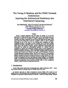
Figure 2: Typical wireless network setup with WaveVideo codecs, error-control modules and filters.
tantly, filters are used on APs where MTs with different channel conditions must be served. In fact, switches and APs use instances of filters and error-control modules for each connection to a receiver. Scalability is ensured by using efficient filters and error-control modules that perform most operations by selection and replication of tagged network frames (packets).
The WaveVideo network and application architecture assumes a large, heterogeneous network with wireless and wired subnetworks, involving different technologies and protocols. Transport interfaces chosen to develop and test the system on are ATM (Asynchronous Transfer Mode) and AAL 5 (ATM Adaptation Layer 5) on one hand, and IP (Internet Protocol) and UDP (User Datagram Protocol) on the other hand. Wireless links are build around the wireless ATM network developed within the European ACTS project Magic WAND [39]. Filter Module
Radio Cell 5
E AP
Architecture and Environment
Filter Module
D
Radio Cell
As an example (cf. Figure 2), consider Terminal 1 (video coder) which sends a high quality video stream to the switch it is attached to. Other terminals in the local subnetwork (e.g., Terminal 2) may receive the same high quality video stream via multicast transmission. Other terminals and MTs in the network do not request as much quality (e.g., for access link bandwidth or cost reasons). Therefore, a filter is located on the outgoing link of this switch towards the network cloud. The same filter mechanism is applied in the other two switches and to APs for each connected MT. These filters are controlled by receivers depending on current channel conditions and user settings. There are crowded radio cells with many MTs (e.g. MT 7) offering less bandwidth to each receiver, while there are MTs being offered the full capacity (e.g., MT 4). MT 5 for example suffers from bad radio conditions at the border of the cell which requires filter settings that produce very low bandwidth. In addition all APs host error-control modules can insert redundant information about the most critical parts of the video stream. This information is generated locally on demand by exploiting the fact that these critical parts can be identified in the video stream.
Video Decoder
Feedback Path
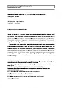
Figure 1: Architectural components of WaveVideo.
As shown in Figure 1, the four software components used in the WaveVideo architecture are coders, decoders, error-control modules, and filters. Coder and decoder modules are located in end-systems which comprise terminals and MTs. Error-control modules are placed directly in APs and MTs and receive feedback on channel conditions by their peers. Filters are used to scale video streams to links with different bandwidth and can be placed wherever diverse qualities must be served. This holds for switches in networks that are connected to more than one subnetwork. But most impor-
By using network filtering to reduce bandwidth and error-control modules to add robustness at every node in the network, it is possible to adapt to various channel conditions and receiver requirements without creating different connections with different layers for quality and error protection levels. While the initiation of error-
4
pensation. Motion compensation allows to exploit the temporal redundancy in video frame sequences. Block matching algorithms (BMA) are most popular in forward motion compensated video coding, because of their compact motion field representation. However, they produce severe blocking artifacts which give an unnatural impression to the viewer. The goal of any video coding algorithm should be to reduce both spatial and temporal redundancy. In this case the video sequence can be represented with fewer bits and can be transmitted in an acceptable quality over wireless channels. Newly emerging coding algorithms deal with the reduction of spatial and temporal redundancy without using any motion compensation, because of its annoying blocking artifacts. Therefore, the WaveVideo approach uses a wavelet-based image compression with extension to the temporal axis (cf. Section 3). Horn and Girod [22] use spatio-temporal resolution pyramids to transmit video robustly and scalable over wireless channels. They combine pyramid coders with multiscale motion compensation, i.e. with an independent motion compensation in each resolution layer. Therefore they are able to decode partial bit-streams and to compress efficiently at different bit rates. Alike, they achieve decoding performance similar to H.263 for their lowpass and bandpass implementations. A similar approach based on the wavelet representation and multiresolution motion compensation can be found in [51] and in [64]. Krishnamurthy et al. [32] developed an advanced motion estimation algorithm which compactly encodes motion fields and recovers from errors even at coarse resolution levels. In contrast to the popular BMA, it does not produce any blocking artifacts. A hybrid motion-compensated wavelet transform coder for very low bit rates has been proposed by Martucci et al. [35] for the MPEG-4 standard. It uses an overlapping block motion compensation combined with a discrete wavelet transform and the zerotree concept for encoding the wavelet coefficients. Its main advantages are its scalability and the good performance, especially on I-frames. Another example of such an hybrid strategy can be found in [53]. The coding algorithm of Belzer et al. [7] is based on the subband decomposition using integer coefficient filters. They adaptively deliver video at rates between 60 and 600 kbit/s as per available bandwidth. The compression is performed on a frame by frame basis without any motion compensation. Cheung and Zakhor [12] suggest a bit allocation approach for a joint source/channel video codec specifically tailored to noisy channels. The source and channel bits are partitioned in such a way that the expected distortion is minimized. The source coding algorithm is
control feedback is provided automatically by the decoder, the specification of the desired quality for each receiver is made by the user. This interaction with users is performed by mapping simple and understandable user-level QoS definitions to codec and transport-level QoS parameters. This report is organized as follows. Section 2 discusses related work in wireless video coding, media scaling including layered and stream based methods, and QoS mapping and adaptation for wireless video. Section 3 and 4 describe the wavelet-based compression algorithms and channel coding, respectively. Filtering, QoS mapping and QoS adaptation are discussed in Sections 5 and 6. Quantitative results for the presented methods are given in Section 7 and the final Section draws conclusions and discusses future work.
2
Related Work
Research in the wireless network area typically focuses either on physical layers issues, such as CDMA versus TDMA, and multiple access protocols, or on higher layer control issues, such as call handoff, hierarchical cell design, and dynamic channel allocation. New wireless networks must cope with the need to carry multimedia traffic, such as video data. Several control issues must be faced, e.g. admission control, dynamic bandwidth control, flow control, resource allocation. A variety of compression algorithms and transmission approaches have been tuned to scale video to different network requirements (bandwidth, error characteristics) which are not traditionally tailored to this purpose, such as ATM networks, the Internet, and wireless channels. Because of their susceptibility to errors, methods for error resilience are needed. In case of video streams, a variety of different coding techniques exist. The most popular of standardized methods encompass ISO’s Motion Picture Experts Group Version 2 (MPEG-2) [25] for video transmission, ITU H.261 [26] and H.263 [27] for low-bit-rate video telephony, respectively. Aravind et al. [4] analyze the behavior of MPEG-2 in presence of packet loss. It is concluded that non-layered MPEG-2 provides an unacceptable quality in wireless networks. Within layered versions of MPEG-2 including dual-priority transmission the scalable, spatial encoding provides best video quality, but the SNR (Signal-to-Noise Ratio) scalable encoding is preferable despite of its worse quality, because of its implementation simplicity. On one hand several 3-D subband coding algorithms have been proposed which focus on the reduction of temporal redundancy [55]. On the other hand, standards as MPEG and H.261 try to reduce spatial redundancy and address the temporal redundancy by motion com-
5
rely on a combination of application and network issues. Yeadon et al. [62] propose to filter hierarchically encoded streams to ease network fluctuations.
based on 3-D subband coding with multirate quantization. The compression efficiency is claimed to be comparable to standards such as MPEG. Wireless links are prone to errors. Unlike wired transport media, they suffer from limited and changing bandwidth. Different error-control mechanisms deal with frame losses and delay jitter due to channel degradation. In a one-way communication the only possibility is forward error-control (FEC). In many wireless channels a feedback channel is provided. Several enhancements to FEC have been proposed [42]. Automatic Repeat reQuest (ARQ) is the mechanism of choice [23], [30]. Different hybrid combinations of ARQ and FEC have been proposed, especially for wireless channels [13], [19]. Source based adaptation schemes suffer from inherent drawbacks. The network-assisted bandwidth adaptation burdens the network with supplementary computations (cf. Section 5). Therefore many researchers proposed a receiver based rate adaptation. Layered compression and transmission allows the receiver to filter the appropriate layer to meet the local capacity of the network. The Heidelberg Transport System (HeiTS) [16] uses a discrete scaling mechanism to allow the receiver to adapt to the delivered bandwidth. Hoffman and Speer [21] describe a video distribution system based on a layered multicast infrastructure. Their temporal hierarchy is created by using multiple rates of a MJPEG (Motion Joint Photographic Expert Group) video. On one hand, the receiver can negotiate with the network to obtain the highest level of available video quality with respect to the network using, e.g., RSVP (Resource ReServation Protocol) [63]. On the other hand it can apply an aggressive adaptation strategy by subscribing to all layers and dropping layers afterwards. This system’s drawbacks are its lack of scalability to larger groups and its inability to deal with bandwidth fluctuations. A similar approach was taken by McCanne et al. [37] in the receiver-driven layer multicast (RLM) scheme. RLM uses IP multicast and an RTP implementation. However it handles subscriptions by performing a set of test joins and by measuring the consecutively workload in the network. This system’s asset is that no changes to the network infrastructure are needed. Quality of Service support is a well studied field in wired networks. Delivering QoS guarantees in multimedia systems is an end-to-end issue, concerning both sender and receiver applications. By admitting a connection, the network must meet the contract it agreed on with the application in terms of service quality. To enable the network to deal with network congestion, different solutions have been proposed. Fixed network based schemes try to provide absolute guarantees on resource availability [2], [31], whereas other designs
In wireless and mobile networks, QoS guarantees are even harder to comply with. Wireless channel fading and mobility have not been considered in traditional QoS architectures for wired networks. Lately, several frameworks have been developed to meet these requirements in wireless and/or mobile environments. Campbell’s and Coulson’s receiver-oriented video delivery system relies on layered compression [10]. Receivers signal reservation messages. The network returns the level of congestion. Then the receiver reacts to congestion by reducing the resource reservation request. The assembly and distribution of reservation messages assumes an ATM network and is based on network filters. A similar approach for wireless networks called Mobiware is described in [9]. Lee [33] proposes two new models: an application model, which couples adaptive applications to the adaptive network resource control, and a service model which introduces a new network service class. This adaptive reserved service provides performance guarantees to adaptive applications on a best effort basis in mobile networks. The framework is still under development. A mobile QoS framework considering both network and application adaptation is investigated in [57]. The application specifies a desired and a minimum needed QoS, which allows QoS degradation and upgrade to meet congestion fluctuations in mobile networks. Furthermore, the delivered QoS moves with the user in the mobile network. The shadow cluster concept [34] uses a predictive resource estimation scheme to cope with QoS reservations on the network layer. A similar approach is taken by Oliveira et al. [43]. They both do not consider any application adaptation possibilities. Naghshineh and Willebeek-LeMair [41] propose a framework that bridges multimedia application and network needs. The multimedia stream is divided in several substreams with different QoS requirements. All components of the framework, i.e. network switches, access points, services and signaling, routing and control protocols, try to monitor the required QoS. Only few researchers proposed a truly integrated, adaptive video coding architecture. Campbell is working towards such an integrated approach. In this report, an end-to-end architecture for this purpose is presented. The WaveVideo prototype includes joint source/channel video coding algorithms, a filter architecture for receiver-based media scaling and error-control methods to cope with a wireless environment.
6
3
WaveVideo Compression Algorithms
On the receiving side, tagged packets are directly decoded into an empty wavelet tree, thus adding significant coefficients to it. Whenever the tree is completed or an external event occurs, such as a deadline is reached to play a video frame, the wavelet tree is processed by the inverse WT (IWT) and a YCbCr image is produced which may be converted to RGB, depending on the video hardware used. An additional step is the estimation of the quality which is approximated by the completeness of the reconstructed wavelet tree (cf. Section 4.2 and 6.5).
The developed WaveVideo coding method is a lossy compression based on the wavelet transformation (WT) and temporal redundancy elimination. It was first described in [14] and has undergone a major revision and many enhancements since. The outline of both the coding and decoding method is presented in Figure 3. Video is fed into the coder either in RGB or YC bCr color space. The color-separated signal is transformed into frequency space yielding a multiresolution representation or wavelet tree of the video image with different levels of detail (cf. Figure 4). This transformed YCbCr Video Input RGB Video Input Buffer Allocation
Inverse Wavelet Transformation
Compression Ratio Feedback
Wavelet Transformation
LL-Cache
Delta-Buffer Delta-Quantizer
Quantizer RLZ-Coder LL-Interleaving
Error Estimation RLZ-Decoder and Re-assembly
Tagging, Headers, Segmentation
Tag/Header Decoder
Wireless Network
Wireless Network
Spatial Compression
Spatial compression attempts to eliminate as much redundancy from single video frames as possible without introducing a perceptible degradation of quality. This is done by firstly transforming the image from the spatial to the frequency domain and secondly by quantizing and compressing the decorrelated output. A twodimensional discrete wavelet transformation (DWT) is applied to the image. The DWT is implemented and approximated using iterated discrete-time filters [58] which are applied recursively as shown in Figure 4. For luminance (Y) and color difference (CbCr) channels a similar tree of low- and high-frequency subbands is generated. More precisely, a 2-D transformation step from one level to the next is assembled by a horizontal and a vertical 1-D transformation performed in series. Implemented as low- and high-pass filters with subsampling, this procedure yields four subbands of a quarter of the original size. LL-subbands are recursively passed to the next lower level for further transformation, while subbands containing high frequency signals (HL, LH, HH) are subject to quantization and compression. The LL-subband of the lowest level is also needed for recon-
RGB Video Output
Color Conversion and Up-sampling
Color Conversion and Sub-sampling
I/∆Frame
3.1
Figure 3: Video coder and decoder connected by a wireless network.
RGB
image is compared to a previously recorded one and it is decided, whether a new intra-frame (I-frame) or difference-frame (∆-frame) is sent to the quantizer and RLZcoder (Run-Length Zero coder). The RLZ-coder is a simple and lossless run-length coder which is optimized for the coefficient distribution of the wavelet transforms. The last two stages of the coder produce the channel format which is sent over the network. Based on feedback from the receiver, the placement and degree of redundancy of low-frequency (LL) subbands and the segment size is selected. Finally, tags and headers describing the semantics of each packet are added. These packets contain a compressed coefficient representation separated by subband, by quantizer range and by color channel.
Cb Y
LL LL
LL
HL
LH
HL
Cr LH
HH
LL
HL
LH
HH
HH
HL LH HH LL HL LH HH
Low-frequency subbands; only smallest size is encoded Quantized and encoded high-frequency subbands
Figure 4: Schematic of wavelet decomposition of luminance channel and subsampled color channels.
7
As variants of Daubechies’ filters, psycho-visually tuned versions were integrated, too [40].
struction, since it is the root of the reconstruction tree. All non-redundant subbands needed for decoding are grouped by shadowed boxes in Figure 4. The maximum number of transformation levels depends on the size of the original video frames and is limited to 8 levels for large formats, such as High Definition TV. If a color subsampling scheme is used, as shown in the example, the luminance channel can be transformed one level deeper than the color channels. Transforming full images instead of small blocks has several advantages. Larger images can be processed more often which increases the number of high-frequency coefficients and, thus, more redundancy can be removed. Compared to standard DCT-blocks of 8 by 8 pixels, which corresponds to a three-level transformation, the common video formats can be transformed from 4 (QCIF) to 6 (PAL) levels using the WT. Generating these multiresolution representations and coding them grouped by level-of-detail rather than locality allows decoders and network stream filters to extract only the desired information. For random loss occurring in wireless networks, the multiresolution representation can produce partial reconstructions that spread loss of information over the whole image. Since the HL and LH subbands contain information about edges, such incomplete images lack sharpness, but never fall short by whole image areas, such as blocks. The choice of a wavelet basis for video compression was based on reconstruction properties and runtime complexity. Since many suitable candidates were found, the wavelet basis has been included as a coder and stream parameter with a preset default value. Generally, complexity for wavelet filters is O(n), where n is the number of filter taps. The one-dimensional n-tap filterpair is applied as follows: n–1
l k = ∑ L˜ i x 2k –i0 + i i=0
An interesting class of integer-based reversible wavelet filters and a general method to develop them was described by Chao and Fisher in [11]. Filter coefficients are represented by multiples of the power of 2 which eliminates rounding and loss of arithmetic precision completely. The CF53 type, using a 5-tap low- and 3-tap high-pass filter, was found to have both required capabilities: good image reconstruction properties comparable to Daubechies’ 6-tap filter and very efficient implementations. Due to its shortness it cannot produce as optimal results as typical filters used for image processing which are usually longer (7 to 9 taps). Such wavelet filters, as discussed in [1] and [3], try to achieve optimal reconstruction results. The CF53 filter is as a compromise of reconstruction image quality and low runtime cost. The algorithm to calculate lk and hk needs only 4 add and 2 shift operations and by limiting the transformation depth to 5 levels (this is equivalent to 10 1-D wavelet filter iterations), coefficients can be represented as 16 bit integers without loss of precision. Furthermore, this compact integer representation allows to use modern SIMD-type (Single Instruction Multiple Data) instructions which are surfacing on many processor architectures recently (they are also known as “multimedia”-instructions). Such instructions execute the same arithmetic operation in parallel on small integer values in large registers, i.e. on four 16 bit values in a 64 bit register. For wavelet filters used in WaveVideo this means that in theory four pixels can be read and processed in parallel and four coefficients can be written back. In practice however, several issues had to be handled. The iterative subsampling leads to small pixel rows and columns which are no longer divisible by four requiring special border treatment. This happens in addition to the well known border treatment for the WT itself which was solved by wrapping the images both vertically and horizontally around (modulo). 1-D filters work differently for horizontal and vertical filters. While horizontal filters parallelize the algorithm for each filter step, vertical filters can process four columns at a time and achieve near optimal speedup (see Section 7.3 for a specific processor example and speedup results).
n–1
and
hk =
∑ H˜ i x2k –i
0
+i
.
i=0
L˜
and H˜ are the low- and high-pass filters, x the pixel values with row- or column-index i, and k is the index of the filter output. Iterating with steps of 2k automatically introduces the desired downsampling by 2. Filter coefficients are real numbers in the range [-1,1]. Using a fixed-point format for these filter coefficients, the algorithm can be implemented for arbitrary wavelets by multiplication-free table lookups. Depending on the number of taps and filter coefficients, this method offers only a limited number of transformation levels within a given precision. For common video formats and some short wavelet filters a precision of 16 bit has proven to be sufficient. Using this approach, Daubechies 4- and 6-tap filters were employed [15]. Having 2 and 3 zero moments, respectively, they are suitable to reconstruct natural images and offer a good compromise between image quality and filter length.
Once an image has been transformed into frequency space, the correlation contained in typical natural pictures is dissolved and the actual compression step introducing loss is performed. Theoretically, the multiresolution representation given by the WT is reversible without any loss. In practice, this is only possible, if no loss of arithmetic precision occurs (i.e. the CF-type wavelets are used). For effective compression however, it is more interesting to introduce controlled loss by quantization of the high frequency coefficients.
8
c, c > q t cq = , 0, c ≤ q t
a)
where c and cq are coefficients and quantized coefficients, q is the quantization factor and t is the current transformation level (higher indices indicate lower resolution), produce a better peak signal-to-noise ratio (PSNR) at the same output size. For quantization of color difference channels a parameter was added to the coder to allow for quantization in favor of the luminance channel which is more important to the HVS. Another special case for quantization is the motion difference frame of videos which is discussed in Section 3.2. For the reconstruction of video streams it is desirable to have a fine grained control over the image quality in network video distribution. Consider for example a hospital, where the same ultrasonic video is shown to experts and patients, or it is displayed on screens with different spatial resolution or color/grayscale depth. Reconstructing images from different subband levels is too coarse. It is better to offer a video representation which allows the extraction of different quantization levels for each subband. In WaveVideo the hard-thresholding quantizer was enhanced to extract ranges as shown exemplary in Figure 7 to code and transmit different q-ranges in different network frames. Up to 8
b)
Figure 5: Five-level decomposition of the Y-channel from Akiyo; a) No quantization applied; b) Same image at q = 25. Different subbands are visually enhanced according to their coefficient distribution.
Distribution
Usually, transformed images have already a large part of zero-coefficients and only decorrelated features are represented by nonzero values (cf. Figure 5). Statistical analysis of the coefficient distribution shows that not only zero values, but small values in general dominate the transformed image. An example of the coefficient distribution of the first frame of the test sequence Akiyo is depicted in Figure 6. These small coefficients are a premier target for elimination, since they correspond to small, barely visible features of the original.It is even possible that the quality of noisy images is improved by removing such coefficients. Note that only the logarithmic scale of the distribution makes it visible. A linear scale would only show a single peak at zero.
cq
cq
10000 100
-20 -5
c 5
1 -200
qt = q ⁄ t ,
-100
0
100
20
-20
c 20
200
Coefficient Value
1st quantizer
2nd quantizer
Figure 6: Wavelet coefficient distribution of an unquantized video frame.
Figure 7: Multirange quantizers example setup: Coefficients from |5| to |20| are coded into the first range and values above |20| fill a second range which is filled into separate packets.
Due to complexity restrictions only scalar quantizers were considered in WaveVideo. Uniform quantizers, which map a region around the origin of the distribution to zero, have proven to be nearly optimal [54] and very simple. Additionally, efficient implementations exist. Several variants of soft-, hard-, and step-thresholding functions were tested with typical videos and are part of the coder. They can be selected by the video stream coding (cf. Section 4). The default quantizer is set to a variant of the hard-thresholding function. The tricky part with quantizers is to find the optimal choice of quantization factors for different resolution levels and luminance/color channels. Quantizing wavelet transforms of all resolution levels with the same factor has the disadvantage of removing details from images that are needed for further recursive reconstruction steps. We have found that quantization functions of the form
ranges can be defined and coded which gives in combination with the subband information a very fine grained control over quality extraction (cf. Section 6.4). This coding characteristic offers more flexibility, when a network stream is filtered or a video is decoded. It does not decrease compression efficiency, but increases channel coding overhead slightly (cf. Section 5.1). It is noteworthy that the quantization function is integrated into the output-stage of the vertical forward WT to reduce unnecessary memory accesses. The function itself is implemented as lookups into pre-calculated tables. A visual example for the compression of single video frames using CF53 filters and the multilevel hardthresholding quantizer is given in Figure 8. The first frame from the test sequence Akiyo in CIF resolution (352 by 288 pixels) is used and a smaller area (a quarter of the CIF frame) is enlarged to demonstrate the result
9
let-based codecs, this fact could be exploited to approximate motion vectors by searching in low-resolution images first and refining these vectors afterwards. The basics of finding motion vectors in frequency space has been described in [64]. For motion compensation in frequency space, block matching algorithms that find these vectors must be modified to account for the shift-variant behavior of wavelets. It was shown for WaveVideo that such a method, besides its complexity, does not improve the speed of finding motion vectors and is roughly comparable to fast search algorithms [17] working on blocks in the spatial domain. Not only the higher coding complexity was a reason for not applying MC in WaveVideo, but also the difficulty of transmitting this information over a lossy channel. Motion vectors, when lost, can lead to very annoying artifacts, because they are crucial for the decoding process. Although there has been recent work [59] in the context of H.263+ to protect MVs from errors, it is still a critical issue in wireless networks with bursty errors.
of the reconstructed images. In Figure 8b), c), and d) weak, medium, and strong quantization values are used, respectively. While the weak and medium quantization only softens edges slightly, strong quantization blurs the image significantly. However, even at a compression ratio of 40:1, no hard artifacts like blocks, as in DCTbased compression methods like JPEG, are introduced. For aggressive quantization typical filter effects, like total loss of edges and over-oscillation near small objects, occur. The compression is given as the ratio of the size of the 12 bit YCbCr image and the size of the compressed output image; additionally, the bitrate in bits per pixel (bpp) is given.
a)
b)
c)
d)
A simpler and more robust approach based on motion detection was followed in WaveVideo (cf. Figure 3). It is a compromise between methods working on a frame by frame basis (e.g., [7] which was also targeted to wireless video) and schemes applying MC. An earlier version of WaveVideo [14] started out by segmenting spatial difference images into regular quadtrees. This method has the advantage that non-moving areas do not need be transformed, thus saving substantial computing resources. However, in terms of compression performance, this method produced a higher bandwidth stream than transformation of full difference images would, because small blocks of an image can be compressed with no or only few transformation steps. Furthermore, the choice of motion-blocks can lead to blocking artifacts. One could correct this drawback by overlapping block schemes. Surprisingly, the best solution is to extend the overlap to the complete image area. Since non-motion areas produce zeroes for the delta, they can be compressed optimally and do not increase the size. The only drawback of increased computational complexity has been accepted and could be compensated with parallel implementations of the WT. Furthermore, the difference is calculated in frequency space which produces better results.
Figure 8: Example of still images. a) Detail from original video frame; b) Compressed image at 34.9 dB PSNR, 20:1 (0.60 bpp); c) 30.8 dB PSNR 40:1, (0.30 bpp); d) 29.2 dB PSNR, 57:1 (0.21 bpp).
3.2
Temporal Compression
Many algorithms for video compression based on wavelets were proposed [58]. Some of them have been evaluated and tested in the context of wireless video. In principle, a video stream is a 3-D data structure that is highly correlated. The wavelet-based approach described for image compression can be extended to the temporal axis by decomposing multiple video frames into spatio-temporal pyramids. Others have shown that this can be very effective in terms of compression [55]. But this method has also several drawbacks. Firstly, it requires too much computational power for real-time codecs and, secondly, it adds a considerable coding delay, since a minimum of 4, 8, or more frames must be transformed together which is not acceptable for interactive communication. Next, the well-known method of motion compensation (MC) was evaluated. The procedure to find motion vectors (MV) in blocks of an image in order to make two frames ti and ti+1 similar, is usually applied to the image data itself. If there is already a multiresolution decomposition as in the case of wave-
An example from Akiyo, comparing ∆-frames in the spatial and frequency domain is shown in Figure 9. For better visibility, the difference between frame number 16 and 19 is shown and the output images are amplified. The operating mode for wireless transmissions builds these differences on the basis of the last I-frame. An adaptive algorithm, which compares the floating average compression ratio with the current output produced by the RLZ-coder (compression ratio feedback, cf. Figure 3), decides, whether a new I-frame is needed or not.
10
a)
targeted to zero runs, which dominate the wavelet coefficient distribution (cf. Figure 6), it also allocates bits optimally to symbols representing different lengths of zero-runs and formats of coefficients. Experiments with test videos have shown that short runs having less then 64 consecutive zeros make up the most occurrences and are encoded together with the symbol code in 8 bit. Longer runs are coded using 8 or 16 additional bits. The same method is applied to the significant coefficients to distinguish small and large values. These assumptions about the coefficients hold reasonably well for the range of common quantization values. Using the selected quantization factor to control dynamic bit allocation could be used as an enhancement without additional runtime cost but is not applied in the current coder.
b)
Figure 9: ∆-frames in spatial and frequency domain.
For video contents increasing motion over time, this method produces optimal compression values. For a typical test video this is generally true (cf. example shown in Figure 10). For applications with very little motion (e.g., surveillance cameras) a limit can be set on the length of runs of ∆-frames. Setting this parameter to zero even allows to emulate a frame by frame behavior of the coder (similar to systems such as MJPEG (Motion JPEG) or the one described in [7]). An additional mode called archive-mode was integrated into the coder to adapt to very good channel conditions, too. ∆frames are calculated with reference to the last video frame and not the last I-frame. Since I-frames are inserted at regular intervals (typically every 1 to 10 seconds), errors accumulate only over these periods permitting very little loss. Applying this scheme doubles the compression ratio for typical low-motion test videos. Finally, ∆-frames are quantized differently. The distribution has even more coefficients around zero than I-frames (cf. Figure 6) for typical low- and mediummotion videos.
4
Channel coding presents the structure of WaveVideo data streams. It includes stream format, transport encoding, error control and recovery, and synchronization of the sender and receivers in a multicast scenario.
4.1
[Bytes]
5000
100
50
0
0
Network Frame Tagging
Adapting QoS of the video stream in the network required a hierarchical stream data format. The network packets belonging to certain quality set need to identifiable. This can be accomplished by labeling the individual network frames with a tag, describing the frame’s contents with respect to the video stream. There are several advantages of such a label. It makes the stream immune to packet reordering in the network, loss of packets does not render the remaining of the stream undecodable, and most importantly it allows for reduction of the stream by selectively dropping packets belonging to a particular quality set. The possibility to reorder the packets is exploited to distribute the errors of an typical bursty error wireless network more evenly over the packets making up a video frame. Having the errors distributed makes them less visible. The tag is interpreted in the receiver to associate the received data to individual video frames and within a single video-frame to correctly place it into the applicable leaf of the wavelet tree. To enable filtering of the video-stream in the network by selectively dropping network-frames the tag has to contain fields identifying the subband and level of the hierarchical WT, quantization layer, the color channel and a (sequence-) number uniquely identifying packets belonging to one videoframe (Table 1). Computing - and network bandwidth efficiency require the tag to be short and a multiple of common computer word sizes (e.g. 32 bit). The various fields are aligned such that filtering can be performed with a two stage table lookup in tables of less than 64K boolean entries (cf. Section 7.4).
10000
[Frame #]
Figure 10: Adaptive insertion of I-frames.
3.3
Channel Coding
Entropy Coding
As a last step, I- and ∆-frames have to be compressed to a more compact representation. Due to the long runs of zeroes or small values most transform coders apply run-length encoders (RLE) followed by an additional lossless stage (e.g., a Huffman coder). Advanced techniques designed for wavelet transforms, notably EZW (embedded zero wavelet) [50], exploit furthermore the fact, that there are still dependencies left between resolution levels. Although EZW produces attractive compression results, it would be difficult to apply them to WaveVideo since a design goal was to produce independently coded resolution levels in order to manipulate the video stream later in network nodes. Therefore, the classical RLE approach was chosen and implemented as the RLZ variant. This coder is not only
11
Size (bit)
3 3
Play
1
Color channel Recursion depth
2 3
Direction
2
I/∆-frame
1
Crypto
1
Sequence number
14
X-Header
Entropy Coder
q-layer
Play Color Channel
2
3
2
Direction
1
1
1
I/∆-Frame Crypto
3
Recursion Depth
3
ATM Cell Header
AAL5 DataATM Payload Padding
AAL5 Trailer
ATMData Payload ATMData Payload
I-Frame ATM Payload Data Header
ame
5-fr
AAL
Figure 12: ATM cells of an AAL 5 frame containing WaveVideo network frames. The payload of the AAL 5 frame starts with the tag optionally followed by a header and the quantized, RLZ encoded coefficients of the WT subband.
Figure 12 shows ATM cells of a single AAL 5 frame carrying a tagged network segment of the video stream.The tag constitutes for the first 32 Bit of the AAL 5 frame. Fields to Error detection and network packet size are assumed to be part of the transport infrastructure, AAL 5 in the example [29]. The trailer containing this information is recognized by the payload type field (PT) [28] of the ATM cell.
4.2
Figure 11 shows the bit layout of the tag, which extends every network frame. Every quantization level 2
ATM Cell Header
no extension header, Segmentation header Specifies the method used for entropy encoding. Specifies the quantization layer. Allows the filter to forward I-frames as references to subsequent ∆-frames. The frame will be transmitted and stored but not decompressed or the frame will be decompressed Channel of luminance, chrominance separated model (YCbCr). Specifies the level within the wavelet tree. Specifies the LL, LH, HL, HH subbands ∆-frame, I-frame The other bits of the label are encrypted if this bit is set. All network packets of the same videoframe share the same sequence number.
2
Tag
Extension Header Entropy Coder q-layer
Usage
ATM Cell Header
Field
ATM Cell Header
Table 1: Fields of the network tag. Bits are assigned in the order.
Error-Control and Recovery
A hybrid scheme for error-control is applied in WaveVideo. Retransmissions are deliberately avoided, as they introduces unpredictable delays, e.g. in a handover scenario, and do not scale well with larger number of receivers. A real challenge was the particularly bad error characteristics of the radio access environment. The decoder must be capable of coping with long error bursts of in oder of hundred milliseconds, where up 60% of the network packets are lost [38], and an average network packet loss rate of up to 10% (cf. Section 7.2). Of course, image quality is degraded with longer error bursts, but synchronization is not lost and artifacts, such as blacked out regions and phantom scene elements are extremely rare. In this sense, the joint channel and source coding scheme of WaveVideo behaves under heavy network error conditions more like a badly tuned analog video transmission system. This tolerance to errors is based on four measures: The WT decorrelates complete video frames. Errors of missing elements are thus distributed the over the whole image reconstructed by the IWT, which generally results in reduced sharpness. Furthermore, segmentation is used for improving tolerance to transmission errors. The presence of a segmentation header is signaled by setting the extension header field to one (cf. Table 1). Segmentation is performed in the coder and network filters. Segmenting in network filters allows for adaptation to links with a particularly high error rate. In the wireless scenario the AP resegments video streams to adjust to every mobile terminal’s individual radio channel characteristics. Network filters could also reassemble segmented frames into a single packet to reduce overhead. In the cell switched environ-
14
Sequence Number
Figure 11: Bit layout of the tag. The MSB is the left most bit of a 32 bit word.
of every subband of the wavelet transformed single video frame is transmitted in a individual network packet. Such a packet may exceed the maximal specified size of network packet. Adding a segmentation extension header allows for breaking such packets up into smaller sized packets. The tag also contains a field identifying the entropy encoding scheme applied to the packet’s data. Different entropy encoders may be needed to compensate for differing coefficient distributions of the frequency subbands (LL subband and higher frequency subbands). The play flag is used in networks filters to pass reference data (I-frames). The algorithm for adaptation of the frame rate chooses the optimal discrete sequence of frames to be filtered given an source and target frame rate. If an I-frame near the next to be passed frame is encountered it is passed on, but marked not to be played out. It will serve as the reference frame for subsequent ∆frames. The WaveVideo packet tagging is well suited for partial encryption of the data. By encrypting the tag and assuming random packet ordering and near to perfect entropy encoding, the whole video stream can be rendered unintelligible.
12
a)
b)
c)
d)
goal of joint source and channel coding was to design the encoder in a way that it only removes as much redundancy from the video stream possible without sacrificing error-tolerance. Besides segmentation, interleaving of frames and additional LL-subband insertion, coding of ∆-frames relative to the last I-frame (cf. Section 3.2) also contributes to the error resilience of WaveVideo by avoiding error accumulation. Still, a remaining cause of concern is the total loss of an I-frame. As an approximation the LL-subband of the last played out video-frame is used. This can, however, lead to significant blur, since in the applied adaptive scheme for insertion of I-frames, an I-frame indicates a significant change of the scene. All the presented measures to improve error tolerance are all forward oriented. However, to determine the optimal value for the parameter r, the insertion rate of redundant LL-subbands and the optimal segment size requires feedback from the MT. For this purpose a feedback channel exists. On the feedback channel the MT sends the percepted error rate back to the sender (cf. Section 6.5). The perceived error of the link is estimated in the MT, based on the difference of expected and received coefficients of the wavelet tree. To account for the fact that quantization is less visible in higher levels of the wavelet tree, coefficients are weighted inversely proportional to the size of their subband. The resulting error rate is averaged over a selectable number of video frames (default 10) and then fed back on the control channel (cf. Section 5.2) to the first filter upstream, the AP. The error control module aggregates the error rates of all outgoing streams by the mean of the maximum function and hands this aggregated error rate upstream. Eventually, the source of the stream is reached and where the segmentation process is started. Segment size will shrink until the threshold is met or a lower bound is reached (100 pixels) efficiently limiting the overhead. For efficiency reasons segmentation is only performed in the sender. Generally segmentation of entropy encoded data requires decompressing and recompression of the data to determine the relative position. This position is needed to assert that also partially received segments can be decompressed at the correct position within the Wavelet tree. Segmentation at the source, on the other hand, does not impose additional runtime cost.
Figure 13: Network frames loss and image quality for video Miss America, QCIF, compression 1:40. The same loss probability (0.1) is assumed for every ATM cell. The shaded parts are lost. a) Large network frames containing a full subbands b) Small network frames containing 100 pels / AAL 5 frame. c) and d) Resulting images at the receiver. The PSNR gained is 9 dB.
ment, however, this does not significantly reduce the load of network nodes, as the number of cells for the segmented frame is not much larger than the original number and, thus, reassembly is never done. In a packet switched environment, such as IP, where the load of routers linearly increases with the number of packets, reassembly should be considered. However, it can be safely assumed that wire-based networks have many order of magnitude lower error rates than wireless networks and, therefore, segmenting filters should be applied at the AP mainly. Interleaving of packets further improves tolerance to errors. The WT’s property of distributing errors over the whole image makes small errors in a particular subband less noticeable than if the full subband is destroyed in a error burst (cf. Figure 13).To achieve this interleaving without additional buffering, the wavelet tree is processed in a pseudo random order by first inorder traversing the tree and storing the references of the leaves in a array and in a second step processing the array in a pseudo random order. The most critical data in the encoding scheme are the low frequency subbands of transformed videoframes (LL-subband), because they form the root of the hierarchical WT data set. This subband is randomly included into the data set at rate r to avoid loss due to error bursts. r is directly proportional to the perceived error rate of MTs. With multiple receiving MTs (multicast) the maximum function of the perceived error rates is to be applied, introducing a (minor) inefficiency for receivers with a superior channel. More sophisticated forward error-control schemes, such as described in [8], have not been applied for two reasons: They need significant computing power and reintroduce redundancy. A
4.3
Transport Layer
The chosen channel encoding is not dependent on AAL 5, but can equally well be used with IP datagrams (UDP). WaveVideo requires the following services from the transport layer: Error detection, discarding of corrupted packets, a packet size field. UDP can be configured to have exactly this behavior. By enabling the computation the CRC checksum and storing it in the
13
Table 2: I-Frame header.
CRC header field error detection can be enabled. The size of the payload also can be derived from the UDP header. The WaveVideo tag itself, however, is part of the payload. Many wireless systems use retransmissions in layer 2 of the radio link to reduce packet error rate. This can become a problem if the magnitude of the introduced delay jitter becomes of the same order as the video frame time, since the playout instance might be missed. The jitter and additional delay is generally unwanted by WaveVideo, as high interactivity and thus low delay was a major design goal. If a maximum round trip of 200 ms is assumed for dialogue applications [52], and a video source of 10 fps the end-to-end delay may at most be 100 ms as the other 100 ms are packetization delay of the video frame. The standard way on the Internet to transport multimedia streams is the Internet Real Time Transport Protocol (RTP) [49]. RTP, however, is not very well suited for transporting WaveVideo. The additional fixed header of 12 Byte introduces significant overhead, since the average network frame size e.g. with a CIF video, quantized with q = 20, is just 36 Byte. Even in multi-layer quantized video streams the majority of packets are less than 50 Byte long. Even worse, the tag without the sequence number would have to be transported in the payload section of the packet, which makes decoding of the RTP header necessary imposing a significant runtime overhead on network filters. The synchronization information sent in every RTP header is not needed in every WaveVideo network packet, since synchronization only needs to be done, when all segments of a video-frame have been received.
4.4
Field
Size (bit)
H-V Resolution
16
Frame rate
16
Time stamp Wavelet base
16
Quantizer
4
Q-Factor
8
∆-mode
1
Color Subsampling
3
4
Usage Horizontal and vertical resolution of the video frames 8.8 fixed point formatted video frame rate Time in ms between I-frames Wavelet base used for transformation of the video frames. Different quantization methods are supported: e.g. hard, soft. Quality parameter of the quantizer Difference coded to: wireless or archive mode no subsampling, 4-2-0 subsampling, 4-2-2 subsampling
an unknown variable. The local playback instant is derived from the sequence number of the frame and the sender’s frame rate which is distributed with each Iframe. Sequence numbers wrap around, therefore, limiting the minimal I-frame rate to 214 times the frame rate of the sender. In practice, much higher minimal I-frame rates are enforced. Clock resynchronization is performed in the receiver, by comparing the local time passed between the current and the last I-frame and the time passed in the sender (time stamp header field). The frame rate can be changed at the sender by forcing an I-frame to be introduced which is including a header with the new frame rate specification.
5
WaveVideo Network Filters
Multicasting a video stream to multiple receivers poses the problem of adapting the stream to the different access link characteristics of the individual receivers. An often cited approach is to code the stream in different quality layers and distribute them on different network channels [36], [37]. A receiver subscribes only to as many channels his access link can handle. While this approach seems very favorable, as it can use the existing multicast technology of the underlying network, it has some major drawbacks. The quality of a compressed video stream is a multidimensional property comprising of image quality, color resolution, and frame rate. Assuming a layered compression technique the sender would send, e.g., 10 non redundant layers of orthogonally quantized video. Subscribing to all channels together, a receiver would get optimal quality, subscribing to the base channel only, it would receive minimal quality. The problem now arises, if the first receiver selects to use its link bandwidth with a high resolution low frame rate stream, while the second receiver aims at receiving a lower resolution high motion stream. Assuming sufficient receivers, all requesting individual quality needs, the sender will have to have channels for each quality layer and frame rate. Obviously, in this scenario
Synchronization
A receiver should be able to join an ongoing transmission at any time. The required base information of the video-stream, such as size, frame rate, and wavelet base, is transmitted in the data stream together with the LL-subband of an I-frame (cf. Table 2). For synchronization and timely playout, the header carries time base and frame rate information of the sender. The header is transmitted with all copies of the I-frame’s LL-subband to reasonably protect this vital information. Sending this information in-line in the stream allows for receivers to synchronize with the reception of the next I-frame. This adds flexibility to change frame rate and size in the sender, as it is assured that all receiver get updated in time. As stated in Section 3.2, I-frames are only inserted, when they improve the overall compression factor. To limit the maximum delay of a receiver joining a ongoing transmission, the maximum number of ∆-frames inserted by the sender is selectable in the coder. Synchronization of sender and receiver is based on the sender’s frame rate. The network delay is treated as
14
more. Within receivers a filter can be used to adjust to the available processing power. Wireless networks are especially suited to demonstrate the advantages of filters in the network. A MT will typically experience varying bandwidth and error characteristics due to new MTs populating the cell and obstacles obstructing the transmission path. Although many modern wireless MACprotocols allow for reservation of bandwidth [39], [45], such a reservation may not be transferable into the next radio cell, when a the MT is roaming, simply because in a tightly populated cell the required bandwidth may not be available. Thus, applications must, be capable of adapting to this situation. Filters in the AP allow for limiting the data stream in the first place in a way that it still matches the QoS required by the user as good as possible (cf. Section 6.5). Using the QoS controller the user can interactively respecify the QoS parameters of the videostreams to optimally meet his requirements under these changed circumstances. Giving a preference profile1 the system may also perform this respecification automatically (cf. Section 6). The QoS specification is sent on the control channel to the filter, which will reconfigure itself, and trigger possible reconfigurations upstream. The video quality parameters of WaveVideo offer a high degree of freedom in the QoS that can be adapted by filters. In Table 3 filter parameters, the used mechanism, and the ranges, are summarized. Image quality and resolution both depend on the multi-resolution pyramid of the WT. The lowest layer of the quantization hierarchy may most likely also eliminate full subbands and can, thus, be equivalent to subband dropping. Generally, dropping full subbands has a more visible effect on the video quality than a highly quantized stream with the same bitrate. Leaving away full subbands, however, allows for saving processing power in the receiver. Instead of processing the inverse wavelet transformation for zero filled subbands, they can be upsampled.
every video-frame is sent over the network more than once. Circumventing this problem requires to send every frame of every layer in its own channel. A receiver subscribes to individual frames and, thus, makes up its own frame rate. If we assume a 25 fps source, 3 color channels (YCbCr), 5 color resolution layers, and 5 quantization levels, 1875 different channels exist to choose from. Having to multiplex and synchronize hundreds of channels in the receiver needs significant computing resources. Even worse, many current operating systems would not even allow for this many channels to be open at the same time. Applying receiver-based quality selection with network filters requires just a single non-redundant stream and offers full flexibility. Filters do not necessarily need to be installed at every node in the network, but only at nodes, where links with greatly differing error and bandwidth characteristics are interconnected. In the wireless scenario these are the APs (cf. Figure 2). Imposing additional application specific computing on the network is a big controversy. While everyone would like the flexibility of such active networks [56], nobody is willing to pay the price in form of lower forwarding power. The processing needed to route packets to the output port already limits the maximum speed of switches, even without application specific computing. Having this in mind, the channel code has been designed so, that every combination of quality and frame rate can be selected only by selectively dropping network frames, based on table lookups using parts of the tag as an index. Synchronization and multiplexing of channels in the receiver is not needed in this approach. Another advantage of network filters is their greater flexibility as they can do segmentation and reassembly, recompression and format conversions. However, these tasks require much more computing power and memory resources than just dropping frames [62]. For the greater flexibility we have decided to pursue the network filter approach, nonetheless, the coding scheme of WaveVideo could easily be used in the multi-channel approach, too.
5.1
Table 3: QoS parameters adaptable in the filter. Video QoS parameters
Network Filters
Color resolution
In general, network filters should be placed on every node of the network. This guarantees optimal use of available bandwidth resources. There are, however, nodes which are especially suited for hosting network filters. These are typically nodes forming access links of receivers: APs of a cellular wireless network, gateways of a local network, or dial-in gateways of an ISP. Other important locations are senders and receivers themselves. In a sender the filter allows for sending only the maximum quality requested by all receivers without having to change the fundamental parameters of the coder. This is especially important for video server applications, where these parameters cannot be influenced any-
Color quality Resolution and size Image quality Frame rate
Mechanism
Range
Subband dropping
2 steps / recursion levels (dropping HH, HL & LH) up to 11 different levels (subsampled color)
Multi level quantization
Typically 3 to 8 levels
Subband dropping
2 steps / recursion levels (dropping HH, HL & LH) up to 13 different levels
Multi level quantization Frame dropping
Typically 5 levels Up to the sender’s frame rate levels
1. A preference profile states which QoS parameters are preferred: e.g. frame rate over image quality (cf. Section 6).
15
sender, having minimized the bandwidth used on the links downstream (cf. Figure 14). The error-control modules behave similar as the QoS filter. If more than one receiver needs additional segmentation, it calculates the maximum segmentation required and updates is own source. This lowers computation cost in the network, as segmentation now will be performed only at one place instead of two. Again, the segmentation request may eventually reach the sender of the stream and can be integrated into the original coding of the stream with no additional computational costs. However, costs will be introduced in the network through higher packet rates and increased bandwidth requirements through the increased number of tags being transmitted.
Frame rate can be adapted by calculating a frame number window of next frames to be forwarded to the receiver. By constantly updating the lower bound, the optimal discrete distribution can be filtered. Frame rate filtering has to take into account that filters can be cascaded and that packets have been lost. Thus, the frame rate algorithm cannot just increment the lower window bound by a constant fraction of input frame rate / output frame rate. The increment used is constantly recalculated and the resulting frame rate compared to the target frame rate of the MT. The maximum error in frame spacing is generated if a rate of just one frame per second less than the senders frame rate is selected. For typical source frame rates of 10 fps and more the introduced jitter is almost invisible to the human eye [52]. Buffering to create equidistant spacing of video frames is not applied in WaveVideo for the, for interactive applications, unacceptable delay introduced.
5.2
6
Mapping of QoS parameters deals with the transformation between two representations of QoS parameters, e.g., between application-oriented and transport-related ones. Besides this protocol-internal QoS mapping, QoS parameters can be mapped onto QoS of underlying systems, called system-specific QoS. QoS mapping is required to provide an easy-to-use parameter set for applications or application programmers, which is automatically transformed into system- and transport-specific ones. This process of QoS mapping has to be performed after QoS parameters have been negotiated between service users and service providers. However, within the WaveVideo wireless system negotiation is omitted due to a clear receiver-driven approach which specifies particular receiver capabilities, like in the Resource Reservation Protocol (RSVP) [63]. These receiver requirements are accepted and delivered to the sender or an appropriate filter, since the sender originally has offered a certain maximum quality. A similar approach to QoS mapping within wired systems is suitable for WaveVideo. However, besides throughput the parameter class of reliability parameters has strong influences in the overall quality achievable for the video application. Applying these QoS mapping prerequisites to the wireless WaveVideo case, application QoS is considered as user-level QoS, transport QoS the special case of network QoS, and system QoS dependent on the video codec. Concerning the wireless case, handovers, roaming, fading, or shadowing may cause a significant change of the current physical transmission capacity. This will be detected by an error estimation module of the decoder and is accessible to QoS mapping functions. Therefore, a highly dynamic adaptation of application data is required to transparently deal with this dynamics, ideally without interrupting the application. Scaling down the bandwidth for a certain period requires an adaptive
WaveVideo Filter Control
As depicted in Figure 14 multiple filters can be located in the path between receivers and the sender. To avoid a centralized control approach, which does not scale well in a multicast scenario with a large number of participants, receiver and filters only have to know the next filter upstream. A control channel to the filter manager of this node is opened to exchange QoS parameters. The filter manager is the control component for individual filter modules. A receiver connects to the filter manager if it wants to receive a video stream. Error feedback and QoS adaptation is also sent to the filter manager, which configures the filter modules for the connected receivers on request. The filter manger uses the QoS values to configure its packet dropping table for particular receiver’s filter. The filter manager sends its own QoS values, which are the maximized values of all receivers 6
D 5
5 Mpbs (17 fps, MQ)
Radio Cell
1 Mbps (20 fps, LQ)
D
D
200 Kpbs (1 fps, MQ)
F
F
E FE
E
FM
C
(25 fps, HQ) (25 fps, HQ)
Radio Shadow
Sender
Switch
AP
D (20 fps, MQ)
Fixed Network
F FM
Terminal Mobile Terminal
Switch
(25 fps, HQ)
C Video Coder E Error Control Module D Video Decoder F Video Filter Module
FM
QoS Mapping and QoS Adaptation
Filter Manager
Figure 14: Example configuration of WaveVideo using network filters to scale the media stream. Every receiving MT can select QoS parameters. Quality is abstracted as LQ (low quality), MQ (medium quality), and HQ (high quality), the real granularity to choose from is much finer grained.
QoS requirements, to the next filter manager upstream. In this way control information eventually reaches the
16
6.2
video codec, as WaveVideo represents, without forcing the application to quit the connection. A suitable range for these QoS degradations is specified in advance and forms an inherent part of QoS mapping.
6.1
Transport QoS
Within the discussed approach the ATM Adaptation 5 layer (AAL 5) is applied for the wireless ATM network including the following QoS parameters as defined in [61]. The token rate in Byte/s defines the generation rate of tokens to be used within one stream which is limited by the token bucket size in Byte. The peak bandwidth in Byte/s defines the maximum throughput achievable on the network. The latency and the delay variation define timing relations, such as the end-to-end latency between sender and receiver and a maximum jitter. Finally, the level-of-guarantee distinguishes between a guaranteed, a predictive, and a besteffort class and the binary network availability defines its accessibility. The current use of these QoS parameters is limited to the actual peak bandwidth (T-QoS) which is dependent on the size of the AAL 5 Protocol Data Unit (PDU) forming the transport frame for continuous video flows. The throughput bound at the ATM cell layer is the peak bandwidth, or Peak Cell Rate (PCR). The payload, however, is bounded by the AAL 5 PDU size and its 8 Byte trailer in addition to the maximum of 48 padding bytes. Therefore, the AAL 5 payload throughput t is bounded by taal5-pay < tatm-pay = #cells . 48 Byte. In case of the wireless ATM network utilized, for any number of application streams the aggregated bandwidth is limited for a given link.
Application QoS and System QoS
To achieve the easiest QoS interface for users of the video application, a single control slider determining the quality Θ. Θ ranges internally from 0 as the best quality to 1 as the worst quality in an approximate linear scale. This application QoS parameter Θ has been adopted for controlling the quality of the overall video stream in terms of hidden transport and system QoS, which are represented in an abstract level as color, sharpness, and motion and for determining system parameters. A single parameter avoids the contradictorily specification of various numerical values for additional parameters.
Figure 15: Graphical QoS user interface.
6.3
Process of the QoS Mapping
Table 4 identifies five QoS parameters for the discussed WaveVideo approach which are handled in different levels for the particular QoS mapping. These parameters define the receiver’s view and are sent upstream to a sender or an intermediate filter. It has to be noted that this process of mapping and its QoS parameters is applicable to every switch, filter, receiver, or sender within the network. The overall quality factor Θ is defined as described above ranging numerically from 0 to 1. The color quality θc, ranging from 0 to rl, determines the quality of the Cb- and Cr-channels. Similarly, the luminance quality θl specifies the quality of the Y-channel, ranging from 0 to rl. Color quality and luminance quality ranges rc, rl are set to 400 due to experimentally obtained bounds. To achieve a fine-grained quality selection, both the quantization range of the multirange quantizer (cf. Section 3.1 and Figure 7) and the number of levels of subbands used for decoding are contained in both parameters θl and θc. This relationship is depicted in Figure 15. While the level of subband is used as a coarse parameter, the multirange quantizer is applied on the subband being the current top-level one only. In this example, three ranges a, b, and c are applied to each subband level in
A graphical QoS user interface as depicted in Figure 15 offers in addition to the Θ a preference profile for system QoS parameters to allow for the specification of rated user choices (first, second, and third) in a highlevel and non-numerical fashion. In case of the WaveVideo approach color resolution and color depth are combined to the color quality, resolution and image quality are merged to luminance quality, and the frame rate determines the quality of motion information. These parameters generally allow for the efficient support of a range of different codec and network parameters. In case of using a special video codec or filter, default values may be specified for parameters, such as the pure bit rate. Finally, a continuous video example is provided at the QoS user interface in case of the WaveVideo approach within a sample window, to feedback current user adjustments. The WaveVideo approach completely hides away any details of these parameters being offered in the preference list from the application to provide an automated adaptation of QoS. Therefore, system QoS (S-QoS) encompass the codec and filter parameters in use: color quality, luminance quality, and frame rate.
17
behavior of the codec based on the overall Θ-factor (AQoS) and according changes of appropriate S-QoS parameters.
successive order. If the last quantization range is reached, the entire subband can be eliminated completely and the next subband is treated in the same fashion. A finer grained range with 4 or 8 value pairs (a to d, or a to h) is applicable, however, the results obtained (cf. Figure 26) need to be taken into account: within the
a
b
c
a
subband level 4
3
2
1
b
c
a
6.4
b
c
The particular set of QoS mapping functions depends on QoS parameters for a special codec/network combination. Therefore, besides the only application QoS parameter Θ, in case of a wireless ATM network the peak bandwidth is available on the network side and the color quality, luminance quality, and frame rate are valid for the appropriate codec and filter. The preference list of S-QoS parameters provides normalized weights wi for each parameter separately (i = 1 .. 3 for the Wavevideo case), Σwi = 1, which are integrated into all mapping functions. Due to three available S-QoS parameters, weights are defined as w1 = 0.2, w2 = 0.3, and w3 = 0.5 for the most, medium, and least important parameter. Instead, w1 = 0.1, w2 = 0.3, and w3 = 0.6 could be used to emphasis a stronger degree of this ordering. In case of four S-QoS parameters wi would be utilized as weights of 0.1, 0.2, 0.25, and 0.45.
a b c quantization ranges
Where a = [0,5], b = [5,10], c = [10, ∞] is based on measurements. Figure 16: Generating fine-grained θl and θc S-QoS parameters from subband levels and multirange quantization.
first and, optionally, second subband level a more finegranular quantization range will be suitable, especially, as future higher bandwidth wireless networks will be available. The frame rate φr defines the number of frames per second received, where the real variable rf defines the maximum range at today 30 fps1. Finally, the peak bandwidth bp defines the maximum transport throughput of the video stream being limited by the maximum link capacity C. The motion quantization factor θm is fixed in relation to θl, since the variance of image quality over time is minimized (cf. Section 3.2). Therefore, it will not be used within the mapping process.
Table 5: Generic QoS mapping functions. Generic Mapping Functions for θl, θc, and φr θl (Θ) = wi2. Θ . rl θc (Θ) = wj2 . Θ . rc
Table 4: Application, System, and Transport QoS. Parameter
Name
A-QoS-1
quality factor
S-QoS-1
color quality luminance quality frame rate peak bandwidth
S-QoS-2 S-QoS-3 T-QoS-1
Symbol
Θ θc
Unit
φr (Θ) = (rf - 6) - ((1-wk2) . Θ . rf) for Θ ≠ 0 and wk < 0.5; φr (Θ) = (rf +1) - ((1-wk2) . Θ . rf) for Θ ≠ 0 and wk ≥ 0.5; φr (Θ) = rf for Θ = 0
Range
–
0…1
–
0 … rc
θl
–
0 … rl
φr
f/s
0 … rf
bp
bit/s
0…C
QoS Mapping Functions
Example mapping functions for a given network/ codec pair are defined for all S-QoS parameters depending on the A-QoS parameter and the order of preference. Table 5 contains in the left column generic functions including weights wi, wj, and wk, with i, j, k = 1, 2, or 3 based on user preferences. An example defines that the luminance quality is rated as the most important one, color second, and motion third. Some mapping results for highly rated luminance are illustrated in Table 6 for a given Θ (best, high, medium, low, worst overall quality). Table 7 shows a different rating, where motion is considered most important.
Mapping the application QoS in terms of the Θ-factor and the order of precedence is distinguished for every codec and network in use. This is necessary due to the varying set of parameters per codec (system QoS) and network (transport QoS). E.g., a traditional IPbased network may not provide any QoS parameters on the transport level, even though the physical layer shows significant variations in available bandwidth and achieved error rates due to radio shades and interceptions. Therefore, a network profile is required to define the set of QoS mapping functions per available parameter. Due to the fact that many QoS parameters determine a nonlinear dependency, a discrete QoS mapping function is required. An initial approach utilizes weighted quadratic functions that depend on the experimented
Table 6: Numeric mapping examples: Luminance rated best. w1 : θ l w2: θc w3: φr
Θ = 0.0 0 0 30
Θ = 0.25 4 9 22.125
Θ = 0.5 8 18 12.75
Θ = 0.75 12 27 7.125
Θ = 1.0 16 36 1.5
Table 7: Numeric mapping examples: Motion rated best. w2 : θ l w3: θc w1: φr
1. High definition video with 60 fps has not yet been included due to today’s relatively low bandwidth wireless networks.
18
Θ = 0.0 0 0 30
Θ = 0.25 9 25 23.8
Θ = 0.5 18 50 16.6
Θ = 0.75 27 75 9.4
Θ = 1.0 36 100 2.2
required. Of course, access links, and especially wireless access networks, do not provide such resources to all users at any time.
Finally, the S-QoS onto T-QoS mapping requires a table-based approach, where the peak bandwidth is always limited by the given maximum payload throughput of the AAL 5 layer, bp (θl, θc, φr) ≤ taal5-pay. Figure 17 depicts in a three dimensional manner this function for bp. Note that the θl and θc axis are in a logarithmic scale, and the frame rate is depicted in a reciprocal manner. Therefore, the optimal quality video is found for bp (0, 0, 0). In addition, it identifies two example values for (a) a 6.4 Mbit/s CIF video stream at a frame rate of 15 fps and (b) a compressed stream at 450 kbit/s CIF for θl = 20 and θc = 2 * θl = 40. Obtained peak bandwidth values for the implemented WaveVideo approach for various Θ ranges are illustrated in Figure 20 and Figure 26 including the subband and multirange quantization as defined within Figure 16. They are utilized to determine a table-based mapping between the 0 … rf and rc scales and the scale for the subband level/quantization range pair. However, this mapping can not be generalized and has to be interpreted with respect to the video itself since it changes slightly in peak bandwidth values.
Therefore, the QoS adaptation process needs to cope with both access link bandwidth limitations and network QoS fluctuations. Access link limits can be given by the upper bound of the physical channel or a preallocated slot made available to a user by a wireless resource reservation system such as the one used in WAND [6]. In either case this limitation is considered a static or quasi-static case (i.e. having no or only very infrequent changes) of fluctuations in network QoS. Frequent changes induced by varying radio conditions, such as deep fades and shadowing, are handled by WaveVideo’s inherent error concealment capabilities as described in Section 4.2.Changes that are known to be of longer duration and higher significance however, are handled by QoS adaptation at the receiver and information about the receiver-perceived quality is fed back to network filter modules and the sender. The estimation of duration of change is not unambiguous and not always available. In WaveVideo external events from the radio subsystem and timers are used to trigger QoS adaptation. Radio subsystems notify decoders or network filter modules on completed handover to initiate QoS adaptation. The T-QoS in the new radio cell is then compared to the previous one and decided whether to change the parameters of the mapping functions. If the estimation of received quality (cf. Section 4.2) changes for a longer period and a customizable threshold is met, QoS adaptation is also triggered. The three parameters (QoS threshold for handover, and timer and threshold for continuous operation) depend heavily on the wireless network used and must be obtained by measurements. For heterogeneous networks with different wireless technology the type of air link could serve as an additional parameter for the estimation process (which is currently not implemented in WaveVideo). It should be noted that this procedure of QoS adaptation differs significantly from the “hard guarantee” approach that monitors requested T-QoS specifications and can only react by dropping connections when the specification is violated. However, traffic classes for wireless ATM or other mobile systems providing QoS could still be employed to prioritize video over non-realtime data streams and QoS adaptation is used within the limits of reserved resources.
θc
40
(b) Θ
= 450 kbit/s
20 5 θl 30
(a) Θ = 6.4 Mbit/s
5
20
40
10 1
2
1/φr Figure 17: Peak bandwidth bp as a function of three S-QoS parameters for two example videos.
6.5
QoS Adaptation
In mobile and wireless networks, fluctuations of network QoS, most notably bandwidth and BER, can require applications to change their requested service quality. The goal of QoS adaptation is to react to such changes and to handle them without user intervention. For that purpose, the QoS mapping functions described in Section 6.4 are used. Increasing the single user parameter q on a non-bandwidth-limited channel would lead to infinite resource requirements. For a real high quality video (e.g. a losslessly compressed CIF video (Akiyo) at 15 fps), 6.4 Mbit/s bandwidth would be
In Figure 18 a diagram of the receiver-centric QoS adaptation approach is shown. Using the defined QoS mapping functions users can specify their overall quality requirement and preference of video properties, depending on application and subjectivity. QoS parameters for filters and senders to adapt the bandwidth on their output links are merged before being sent out, using the two S-QoS parameter sets calculated by QoS
19
512 by 512 pixel image Lena was produced and compressed to a single I-frame on the output stream. The original is a 8 bpp grayscale image. Figure 19 shows the results at compressions ratios of 32:1, 64:1, and 128:1. State of the art still image coders, such as the one described by Shapiro in [50], show a gain of 3 to 4 dB over WaveVideo in this compression range for the same image. This is due to several reasons. The applied CF53 wavelet filters are a compromise which offers good processing performance, but cannot fully compete with optimized and longer filters (cf. Section 3.1). In addition the entropy coder, which is applied, could still be enhanced. However, in order to retain the multiresolution representation, redundancy between different resolution layers cannot be eliminated. Finally, the coding overhead of tags and headers has to be paid for. The coded examples contain tags and headers but do not contain further protocol overhead. For the case of the wireless ATM network described in [39] and the 32:1 compressed single frame video, additional 112 Byte for AAL 5 framing and 912 Byte for wireless ATM cell headers of 6 bytes length each have to be added for the total bandwidth which would reduce the actual compression ratio on the wire to 28.5:1. A comparison of video coders is given for the lowmotion test sequence Akiyo in CIF format (352 by 288 pixels) at 15 fps. The compression ratio and pixel rate are given relative to the size of the original video with a pixel depth of 12 bit (4-2-0 color subsampling). WaveVideo is configured in wireless mode with ∆-frames referencing the last I-frame and in archive mode (cf. Section 3.2), where a very low BER for transmission is assumed. The results for Radius’ Cinepak codec, a vector quantization based compressor, and Intel’s Indeo, also a wavelet-based compressor, are presented in addition in Figure 20. It has to be noted that Cinepak has an asymmetric runtime overhead for compression, while WaveVideo and Indeo are both symmetric and, therefore, suitable for conferencing and other real-time applications. The PSNR values illustrated are for the luminance channel only. For WaveVideo, the variance over the 20 second sequence is less then +/- 0.5 dB. Similar measurements are provided for the mediummotion test sequence Foreman. The resolution is again CIF (352 by 288 pixels) and the frame rate 15 fps. Due to the higher motion activity, in particular camera motion, the compression ratio drops significantly. Since none of the compared codecs employ motion compensation, all of them have to insert more I-frames and, therefore, lose compression. For WaveVideo the difference between wireless and archive mode is less than 1 dB for the same reason of a high I-frame rate. The results are shown in Figure 21. A comparison of WaveVideo in I-frame mode (i.e. no temporal compression) with a commercial MJPEG
User Video Display Decoder Video Source
QoS Mapper
Error Estimator
Coder
Filter/ Error Feedback
QoS Adaptor Handover Indication
Wireless Network
Filter Module
Wireless Network
Error Control
Data Path
Feedback Path
Intra-Node Communication
Figure 18: Receiver-based QoS adaptation relying on error estimation and handover indications from the wireless network.
mapper and QoS adaptor. Unlike in filters where usercentric parameter sets are merged by the maximum function (cf. Section 5), the merge operation between QoS mapper and adaptor takes into account what the user’s preference is and degrades in case of limited bandwidth or increasing BER those parameters of the set {θl, θc, φr} first, that have the highest weights wi, thus being least important to the user. Using tabular reference data for typical conference style videos and the quantitative indication of the error estimator, a new SQoS parameter set can be found quicker than with an approach using regulation mechanisms only. Error feedback is generated only by the QoS adaptor and does not need to be merged. It is sent directly to the next error-control module or sender which can react by changing the parameters re-segmentation, interleaving, and replication of LL-subband information based on a local decision. Using low-frequent updates for errorcontrol feedback, network overhead is reduced, and more importantly, oscillations in the regulation process are minimized.
7
Quantitative Results
This section presents performance measurements obtained from the implementation of the codec, filters, and error-control modules.
7.1
Codec Performance
To compare WaveVideo’s compression performance on still images, a single frame raw-video containing the
20
a)
b)
c)
d)
Figure 19: Original and compressed still images Lena. a) Uncompressed original; b) WaveVideo I-frame compression at 32:1 (0.25 bpp), 30.0 dB PSNR; c) Compression factor 64:1 (0.125 bpp), 26.4 dB PSNR; d) Compression factor 128:1 (0.0625 bpp), 23.4 dB.
compressor is shown in Figure 22 for the Akiyo test sequence. This result indicates also that WaveVideo can increase the compression, when using temporal algorithms, by a factor of about 3 for wireless mode and by a factor of more than 5 in archive mode.
21
Average PSNR [dB]
45 Intel Indeo 4.3 WaveVideo (Wireless Mode) Radius Cinepak 1.8.0.12 WaveVideo (Archive Mode)
40
Test Video
Indoor Environment
35
SRCM
30
25 0
50
100
150
200
250
300
Channel Dispersion
350
Coder
Fluctuations
CIR
FSRCM
BER
MAC ATM/AAL5
Transceiver Characteristics
Decoder
Compression factor
Figure 23: Simulation model for the wireless ATM transmission system.
Figure 20: Video quality measured for WaveVideo and two commercially available codecs using the test sequence Akiyo.
WaveVideo (Wireless Mode) Intel Indeo 4.3 Radius Cinepak 1.8.0.12 WaveVideo (Archive Mode)
40
Average PSNR [dB]
length (i.e. there is no path loss). A detailed description of this model is given in [20] (cf. Table 8). In order to get a channel model that is easier to handle for performance evaluations the continuous state stochastic process describing the signal power of the SRCM was discretized [38]. The resulting finite state radio channel model (FSRCM) allows a description of the time-variant behavior of the SNR at the receiver by a semiMarkov process. Using the OFDM (Orthogonal Frequency Division Multiplexing) signal processing algorithms applied in the Magic WAND modem a relationship between the SNR and the BER or CER (Cell Error Ratio) was found. Thus, the FSRCM is defined by a semi-Markov process, where each state corresponds to a certain BER or CER value. A simple model of the MAC (Medium Access Control) protocol yields the resulting AAL 5 frame loss rate and distribution [6].
35
30
25 0
20
40
60
80
Compression factor
Figure 21: Video quality measured for WaveVideo and two commercially available codecs using the test video Foreman with moderate camera motion. 45 WaveVideo (I-Frames only) Paradigm MJPEG 1.02N
Average PSNR [dB]
40
Table 8: Stochastic radio channel model parameters. 35
Parameter Carrier Frequency Number of Paths Standard Deviation of Path Energy
30
25
20 0
10
20
30
40
50
60
Delay Spread
70
Compression factor
Path Loss MT velocity
Figure 22: WaveVideo in I-frame mode compared to an MJPEG compressor.
7.2
Value 5.2 GHz random, mean: 8 2.0 (shadowing effects) 50 ns (typical for indoor environments) off 1 m/s
To simulate the wireless behavior it was assumed that there is no other traffic on the wireless channel, i.e. there is no delay or loss caused by congestion. Loss of network frames is handled in WaveVideo by setting the corresponding wavelet coefficients to zero which could be interpreted as a total quantization of a certain resolution level. Furthermore, only vertical or horizontal edges of the image are affected, if not many adjacent network frames are influenced by bursty errors.
Error Concealment on a Wireless Channel
To measure the effectiveness of WaveVideo’s error concealment capabilities, the simulation setup as shown in Figure 23 was used. It is based on the wireless ATM system described in [39].Time variant multi-path propagation is taken into account for the modeling of both fast and slow fading (shadowing). A reasonable velocity of the MT at a fixed distance around the AP was chosen to allow for simulation sequences of unlimited
Simulation of the wireless network for the shadowing case shows that momentarily high CER values of 0.5 and more can persist over longer periods (e.g. up to 20 ms at 30 dB radio SNR) and, therefore, many sub-
22
CER
1000000
35
10000
30
100
25
1
20
0.01
15
0.0001
10
Cell Error Ratio (CER)
180
160
140
120
100
80
60
0 40
0.00000001 20
5
0
0.000001
PSNR [dB]
burstiness of the source process [45]. This spread is a result of the MAC scheduler, transmitting cells as close to their deadline as possible. For the simulated environment, mean radio SNRs chosen for the simulation were 30 dB and 26 dB, corresponding to a distance of approximately 32 m and 40 m between AP and MT. The mean CER (BER) for this simulation setup is 0.1 ( 3.3 ×10⁻³ ) and 0.31 ( 2.2 ×10⁻¹ ) respectively. The measurements shown in Figure 24 and Figure 25 illustrate a
bands of a single video frame are likely to be affected at video frame rates between 10 and 30 fps. The test sequence Akiyo, which was used for measurements, is played at 15 fps corresponding to an interval of 66.6 ms between frames. Since interactivity and, therefore, low delay is an issue in our case, no further measures were taken to conceal errors between multiple video frames. However, standard ATM resource reservation techniques were used to spread cells and avoid unnecessary
[Frame #]
Video Quality
35
1000000
30
10000
25
100
20
1
15
0.01
10
Cell Error Ratio (CER)
Video Quality
180
160
140
120
80
100
0 60
0.000001 40
5
20
0.0001
0
CER
100000000
PSNR [dB]
Figure 24: Error concealment for a wireless channel at 30 dB. The momentary CER and the video signal quality are given.
[Frame #]
Figure 24: Error concealment for a wireless channel at 26 dB. The momentary CER and the video signal quality are given. Figure 25: Error concealment for a wireless channel at 26 dB. The momentary CER and the video signal quality are given.
23
bit color). Table 9 summarizes execution times for all coder and decoder blocks with and without using MMX-instructions [46]. The non-MMX numbers are compared to an assembler language implementation which is about 50% faster than optimized C-code. The first part of the table determines overall timings for coding and decoding. For decoding, the timing for the case of color subsampled video streams has been obtained. The first part does not include the time for color conversion and displaying of video frames.
sampling rate of the CER equal to 5 times the video frame rate. This interval of 13.3 ms is in the same order as the mean state holding time of the FSRCM. The CIFsized video was transmitted at a compression ratio of 42:1 (435 kbit/s) and a mean PSNR of 36 dB for the luminance channel. The first measurement (cf. Figure 24) carried out at 30 dB and 0.1 mean CER can be considered a typical case for a wireless system. Most of the time, loss of PSNR for the video is smaller than 4 dB which is not noticeable by the average observer. Shadowing effects on the channel resulting in a CER of up to 0.89 (this corresponds to a very low momentary radio SNR of about 8 dB) are the only situations, where a visible degradation of the image quality is perceptible. The second case was simulated at 26 dB mean radio SNR (cf. Figure 25). These very poor radio conditions can affect video over longer periods. These momentary radio conditions range down to 2 dB with a CER of 0.99. For both simulation runs it must be noted that the chosen channel model is a pessimistic one with deep fades and interruptions of the paths Figure 26 shows two video frames to give a visual example for the two simulations.
7.3
Table 9: WaveVideo performance measured on 200 MHz Pentium PC with and without MMX instructions. Function Coder Decoder Decoder/sub-samples Color YCbCr to RGB Color RGB to YCbCr Horizontal WT Vertical WT Horizontal IWT Vertical IWT Difference
MMX disabled [ms] 175 120 47 43 19 25 21 37 25
MMX enabled [ms] 105 63 44 35 41 12 8 12 11 13
Speedup [] 1.67 1.90 1.35 1.05 1.61 3.25 1.79 3.43 1.87
Results for color space conversion are given separately in the second part of Table 9, since these functions can be eliminated, if the video input signal is already available as YCbCr-format or the playback hardware supports displaying color separated video. It is noteworthy that the available MMX-instructions do not help much, because they are not suitable for 3-D transformations of small values that can be looked up in tables at roughly the same speed. The last part of the table shows the results for the WT for the CF53 wavelet. Implemented as 1-D filters, we compare horizontal algorithms, which parallelize
Computational Complexity of the Codec
This subsection reviews the execution speed of the WaveVideo codec and its algorithms on off-the-shelf hardware. As described in Section 3.1, the algorithms, foremost the wavelet transformation, can be parallelized on processors offering “multimedia”-instructions, such as the Sparc (VIS), Mips (MDMX), or Pentium (MMX). The configuration used for measurements was a 200 MHz Pentium MMX CPU on a Gigabyte 586HX motherboard with 256 kByte of second level cache. The test video employed was Claire (320 by 240 pixels, 24
a)
b)
b)
a)
Figure 25: Figure 26: Video images obtained from the simulation runs at 30 dB and 26 dB mean radio SNR, respectively. a) Frame number 10 from Akiyo at a momentary CER of 14%; b) Frame number 21 from the same test sequence at a momentary CER of 62%.
24
been generated in the color separated space. Standard deviation is about 0.1 dB for the PSNR and 50 Kbit/s for the bitrate. The frame rate of the video is 10 fps. Figure 27 shows the bandwidth requirements and resulting PSNR at different quality settings.
single filter operations and vertical algorithms, which execute four filter steps in parallel for adjacent pixel columns. The timings for transformation and inverse transformation are roughly the same. Finally, the difference calculation of two wavelet trees, which is straight forward to parallelize, yields a less than to be expected speedup, because the function is memory bound. Test-runs on the described machine without specialized hardware-support for video output yield a playback rate of 10 frames per second (fps) including reading from the network and displaying the video.
Computational Complexity
The filtering framework has been implemented on PCs as an application program using IP/UDP for data transport and TCP for the control channel. Filtering of quality has been implemented using as a 14 Bit (16K entries) boolean table and a calculation of the next frame to pass based on the sequence number. In general 2 masking, 1 table look up, 3 compare and 1 arithmetic operations are needed to perform the packet filtering. Data handling and the overhead associated with the general filtering framework leads to a filtering time of about 5 µs per packet on the setup used in Section 7.6. The time spent for filtering can be neglected, when compared to delay of the WinSock-2 IP stack, which accounts for about 10 ms delay.
Network Filters
The luminance channel can be scaled ranging from a sharp to a softened image. Network filters allow for the adaptation of the video stream to receivers’ access link characteristics and computational capabilities. These filters scale color resolution with the two extremes of gray scale image and full color image. The filtering of the frame rate is not shown as it reduces bandwidth requirements approximately linear to the frame rate chosen. Figure 27 has been generated using a QNTSC resolution camera and a frame grabber on a PC (Winnov Videum) to illustrate bandwidth requirements and resulting PSNR at different quality settings. The scene was a typical video conferencing scenario, with a seated person in front of a inhomogeneous steady background. The PSNR measurements are done on the combined luminance and chrominance channels in RGB space to demonstrate the effect of the QoS mapping functions. Due to the noise introduced by the inexpensive video equipment and the measurements in RGB space, all PSNR results must not be compared to results in the compression section or to published results which have
7.6
Implementation Status
The main architectural components of WaveVideo were prototyped in a modular fashion which allowed for tests on different platforms and in different networking and simulation environments. The coder and decoder were implemented as a portable core (i.e. buffer management is an integral part of the codec) which was later adapted to the Video for Windows and ActiveMovie APIs. Using these interfaces, most tools like conferencing applications or nonlinear editors can make use of WaveVideo and standard network protocols such as IP
40
7000 Bit rate 6000
35
PSNR
30
Bit rate [Kbit/s]
5000
25 4000 20 3000 15 2000
PSNR [dB]
7.4
7.5
10
1000
5
0
0
0
.5 Θ
1
Figure 27: Image quality (PSNR) and bandwidth requirements at different filter QoS settings. The Θ is mapped to [0..1] with 0 meaning best quality as described in Section 6.4.
25
sacrificing error tolerance. Error tolerance should be further investigated by including better FEC codes and a closer cooperation with the underlying wireless network. For example, ARQ-schemes applied to the wireless link could be used to increase the reliability of transmission of LL-subbands. Furthermore, the wireless behavior will be investigated on availability of the real wireless system to verify simulation results. As a new idea, it is proposed to integrate cryptographic algorithms to allow for secure transmission of video. The problem of secure video is the encryption overhead of high-quality video which could be addressed by combining source and secret coder and by encrypting the important part of a WaveVideo stream only. Another idea to be investigated is the possibility offered by active networks: Filters and error-control modules could be defined in a more flexible way and distributed to switches and access points when needed.
and ATM become available. Additionally, a test environment was built around these APIs to evaluate the codec’s performance, enhance video algorithms, and, run the wireless ATM simulation. Filter and error-control modules were prototyped and tested as independent processes running in user space.
8
Conclusions and Future Work
The presented results of the WaveVideo implementation have shown the possibility to build a competitive video compression method that is robust being operated on wireless networks. Bursty errors can be concealed in images to a high degree at a low channel code overhead. High error rates or high quantization values blur and soften the image, but do not introduce artifacts. This is even true for the temporal compression algorithm used in WaveVideo. Error-control based on receiver estimated feedback is used to adapt the amount of redundancy introduced by error-control modules or senders which are placed as close as possible to the critical link. Receiver-based feedback from users also contains QoS parameters that are obtained by defined QoS mapping functions. These can work effectively only, when the coding method offers a high degree of scalability and elasticity which is the case for WaveVideo. A unique feature of the architecture is that QoS mapping functions can access and change all defined QoS parameters at any node in the network. Similar QoS mapping functions are used to adapt the video and network parameters when large-scale fluctuations occur. This can be done in WaveVideo without changes to the users originally defined application QoS. WaveVideo filters are capable of handling a multicast scenario in the required efficient fashion. Furthermore, they feature lowest runtime complexity and a fine-grained QoS selection based on all possible QoS parameters. Most of the results were made possible by designing a wireless video system from scratch rather than modifying existing coding methods to match the mobile and wireless requirements. The drawback that no standardsbased method could be employed is alleviated by offering an efficient software-only solution. The difficulty that filters and error-control modules need to be installed on networks nodes before the system can be used efficiently in a general scenario is a drawback compared to the layered approach. However, depending on the application, it might be possible to install such modules on particular nodes, such as APs, only. Future work on the WaveVideo network architecture includes the codec, filter and error-control modules. The compression algorithm itself could be slightly enhanced by a better entropy coder and a more aggressive exploitation of temporal redundancy. However, not all known or possible algorithms can be applied without
Acknowledgments The authors would like to thank their colleagues in the WaveVideo development team, namely Richard Wood, Alexander Schwab, Jan W. Hofte, and Junli Hu for their contributions and programming effort. Special kudos to Jürg Meierhofer for his support with the FSRCM. Part of this work has been performed in the framework of the project ACTS AC085 The Magic WAND, which is partly funded by the European Community and the Swiss BBW (Bundesamt für Bildung und Wissenschaft). The authors would like to acknowledge the contributions of their colleagues from Nokia Mobile Phones, Tampere University of Technology, Ascom Tech AG, Lucent Technologies WCND, University of Lancaster, Robert BOSCH GmbH, University of Ulm, Compagnie IBM France, IBM Zürich Research Laboratory, ETH Zürich, and INTRACOM Hellenic Telecommunications.
References [1]
[2]
[3]
[4]
26
E. H. Adelson, E. Simoncelli, R. Hingorani, Orthogonal Pyramid Transforms for Image Coding, SPIE, Vol. 845, pp. 50-58, Cambridge, MA, USA, October 1987 A. Alwan, R. Bagrodia, N. Bambos, M. Gerla, L. Kleinrock, J. Short, J. Villasenor, Adaptive Mobile Multimedia Networks, IEEE Personal Communications Magazine, Vol. 3, No. 2, pp. 34-51, April 1996 M. Antonini, M. Barlaud, P. Mathieu, I. Daubechies, Image Coding Using Wavelet Transform, IEEE Transactions on Image Processing, Vol. 1, No. 2, pp. 205-220, April 1992 R. Aravind, M. R. Civanlar, A. R. Reibman, Packet Loss Resilience of MPEG-2 Scalable Video Coding Algorithms, IEEE Transactions on Circuits and Systems for Video Technology, Vol. 6, No. 5, pp. 426-435, October 1996
[5]
[6]
[7]
[8]
[9]
[10]
[11]
[12]
[13]
[14]
[15]
[16]
[17] [18]
A. Balachandran, A. T. Campbell, M. Kounavis, Active Filters: Delivering Scalable Media to Mobile Devices, Proceedings of NOSSDAV’97, St. Louis, May 1997 F. Bauchot, G. Marmigere, N. Passas, L. Merakos, S. Decrauzat, MASCARA, a MAC Protocol for Wireless ATM, ACTS Mobile Communications Summit, Granada, Spain, Vol. II, pp. 647-651, November 1996 B. Belzer, J. Liao, J. Villasenor, Adaptive Video Coding for Mobile Wireless Networks, IEEE International Conference on Image Processing’94, Austin, TX, USA, pp. 972-976, 1994 E. W. Biersack, Performance Evaluation of Forward Error Correction in ATM Networks, ACM Computer Communication Review, Vol. 22, No. 4, pp. 248-257, October 1992 A. T. Campbell, Mobiware: QOS-Aware Middleware for Mobile Multimedia Communications, 7th IFIP International Conference on High Performance Networking, White Plains, NY, USA, April 1997 A. Campbell, G. Coulson, A QoS Adaptive Transport System: Design, Implementation and Experience, Proceedings of the ACM Multimedia’96, Boston, MA, USA, pp. 117-127, November 1996 H. Chao, P. Fisher, An Approach to Fast Integer Reversible Wavelet Transforms for Image Compression, Computer and Information Science Inc., October 1996 G. Cheung, A. Zakhor, Joint Source/Channel Coding of Scalable Video over Noisy Channels, IEEE International Conference on Image Processing’96, Vol. III, Lausanne, Switzerland, pp. 767-770, September 1996 M. Chiani, A. Volta, Hybrid ARQ/FEC Techniques for Wireless ATM Local Area Networks, Seventh IEEE International Symposium on Personal, Indoor and Mobile Radio Communications PIMRC’96, Taibei, China, pp. 898-902, 1996 M. Dasen, G. Fankhauser, B. Plattner, An Error Tolerant, Scalable Video Stream Encoding and Compression for Mobile Computing, Proceedings of ACTS Mobile Summit 96, Granada, Spain, Vol. II, pp. 762-771, November 1996 I. Daubechies, Orthonormal Bases of Compactly Supported Wavelets, Communications on Pure and Applied Mathematics, Vol. 41, pp. 909-966, November 1988 L. Delgrossi, C. Halstrick, D. Hehmann, R. G. Herrtwich, O. Krone, J. Sandvoss, C. Vogt, Media Scaling for Audiovisual Communication with the Heidelberg Transport System, Proceedings of ACM Multimedia’93, Anaheim, CA, USA, pp. 99-104, August 1993 B. Furht, J. Greenberg, R. Westwater, Motion Estimation Algorithms for Video Compression, Kluwer Academic Publishers, 1997 M. W. Garrett, M. Vetterli, Joint Source/Channel Coding of Statistically Multiplexed Real-time Services on Packet Networks, IEEE/ACM Transactions on Networking, Vol. 1, No. 1, pp. 71-80, February 1993
[19] R. Y. Han, D. G. Messerschmitt, Asymptotically Reliable Transport of Multimedia/Graphics over Wireless Channels, International Conference on Multimedia Computing and Networking, San Jose, CA, USA, January 1996 [20] R. Heddergott, U. P. Bernhard, B. H. Fleury, Stochastic Radio Channel Model for Advanced Indoor Mobile Communication Systems, Eighth IEEE International Symposium on Personal, Indoor and Mobile Radio Communications PIMRC 97, Vol. 1, Helsinki, Finland, pp. 140 - 144, September 1997 [21] D. Hoffman, M. Speer, Hierarchical Video Distribution over Internet-style Networks, IEEE International Conference on Image Processing, Lausanne, Switzerland, Vol. I, pp. 5-8, 1996 [22] U. Horn, B. Girod, Performance Analysis of Multiscale Motion Compensation Techniques in Pyramid Coders, IEEE International Conference on Image Processing’96, Lausanne, Switzerland, Vol. III, pp. 255-258, September 1996 [23] C.-Y. Hsu, A. Ortega, M. Khansari, Rate Control for Robust Video Transmission over Wireless Channels, SPIE, Vol. 3024, Visual Communications and Image Processing’ 97, Pt. 2, pp. 1200-1211, 1997 [24] A. Iera, S. Marano, A. Molinaro, On the Evolution of Mobile Network Protocols Towards the Support of Multimedia Teleservices, IEEE International Conference on Communications’96, Vol. III, Dallas, TX, USA, pp. 1241-1246, 1996 [25] ISO/IEC 13818-2, Information Technology Generic Coding of Moving Pictures and Associated Audio Information: Video, November 1994 [26] ITU-T Rec. H.261, Video Codec for Audiovisual Services at px64 Kbits/s, July 1993 [27] ITU-T Rec. H.263, Video Codec for Low Bitrate Communication, 1996 [28] ITUT-T I.361, B-ISDN ATM Layer Specification, 1995 [29] ITUT-T I.363.5, B-ISDN ATM Adaptation Layer specification: Type 5 AAL, 1996 [30] M. Khansari, A. Zakauddin, W.-Y. Chan, E. Dubois, P. Mermelstein, Approaches to Layered Coding for Dual-rate Wireless Video Transmission, IEEE International Conference on Image Processing’94, Austin, TX, USA, pp. 258-262, 1994 [31] A. Krishnamurthy, T. D. C. Little, Connection-oriented Service Renegotiation for Scalable Video Delivery, International Conference on Multimedia Computing and Systems, Boston, MA, USA, pp. 502-507, May 1994 [32] R. Krishnamurthy, P. Moulin, J. W. Woods, Multiscale Motion Estimation for Scalable Video Coding, IEEE International Conference on Image Processing, Vol. I, Lausanne, Switzerland, pp. 965968, 1996 [33] K. Lee, Adaptive Network Support for Mobile Multimedia, ACM Mobicom '95, Berkeley, CA, USA, pp. 62-74, 1995 [34] D. A. Levine, I. F. Akyildiz, M. Naghishineh, A Resource Estimation and Call Admission Algorithm for Wireless Multimedia Networks Using the Shadow Cluster Concept, IEEE/ACM Transactions on Networking, Vol. 5, No. 2, pp. 1-12, February 1997
27
[35] S. A. Martucci, I. Sodagar, T. Chiang, Y.-Q. Zhang, A Zerotree Wavelet Video Coder, IEEE Transactions on Circuits and Systems for Video Technology, Vol. 7, No. 1, pp. 109-118, February 1997 [36] S. McCanne, M. Vetterli, Joint Source/Channel Coding for Multicast Packet Video. IEEE International Conference on Image Processing ‘95, Washington DC, USA, pp. 25-28, October 1995
[50] J. M. Shapiro, Embedded Image Coding Using Zerotrees of Wavelet Coefficients, IEEE Transactions on Signal Processing, Vol. 41, No. 12, pp. 3445-3462, December 1993 [51] K. Shen, E. J. Delp, A Control Scheme for Data Rate Scalable Video Codec, IEEE International Conference on Image Processing, Vol. II, Lausanne, Switzerland, pp. 69-72, 1996 [52] R. Steinmetz, Human Perception of Jitter and Media Synchronization, IEEE Journal on Selected Areas in Communications, Vol. 14, No. 1, pp. 6172, January 1996 [53] R. Talluri, K. Oehler, T. Bannon, J. D. Courtney, A. Das, J. Liao, A Robust, Scalable, Object-based Video Compression Technique for Very Low Bitrate Coding, IEEE Transactions on Circuits and Systems for Video Technology, Vol. 7, No. 1, pp. 221-223, February 1997 [54] N. Tanabe, N. Farvardin, Subband Image Coding Using Entropy-coded Quantization Over Noisy Channels, IEEE Journal on Selected Areas in Communications, Vol. 10, No. 5, pp. 926-942, June 1992. [55] D. Taubman, A. Zakhor, Multirate 3-D Subband Coding for Video, IEEE Transactions on Image Processing, Vol. 3, No. 5, pp. 572-588, September 1994 [56] D. L. Tennenhouse, J. M. Smith, W. D. Sincoskie, D. J. Wetherall, G. J. Minden, A Survey of Active Network Research, IEEE Communications, Vol. 35, No. 1, pp. 80-86, January 1997 [57] C.-K. Toh, Mobile Quality of Service for Wireless ATM Networks: An Adaptive Approach, Proceedings of ACTS Mobile Summit '97, Aalborg, Denmark, pp. 344-349, October 1997 [58] M. Vetterli, J. Kovacevic, Wavelets and Subband Coding, Prentice Hall, New Jersey, 1995 [59] G. Wen and J. Villasenor, A Class of Reversible Variable Length Codes for Robust Image and Video Coding, IEEE International Conference on Image Proc., Santa Barbara, CA, USA, October 1997 [60] R. M. Wood, G. Fankhauser, R. Kreula, E. Monni, QoS Mapping for Multimedia Applications in a Wireless ATM Environment, Proceedings of ACTS Mobile Summit '97, Aalborg, Denmark, October 1997 [61] J. Wroclawski, The Use of RSVP with IETF Integrated Services, Internet Draft, September 1996 [62] N. Yeadon, F. García, D. Hutchison, D. Shepherd, Filters: QoS Support Mechanisms for Multipeer Communications, IEEE Journal on Selected Areas in Communications, Vol. 14, No. 7, September 1996 [63] L. Zhang, S. Deering, D. Estrin, S. Shenker, D. Zappala, RSVP: Anew Resource ReSerVation Protocol, IEEE Network, Vol. 7, No. 5, pp. 8-18, September 1993 [64] Y.-Q. Zhang, S. Zafar, Motion-Compensated Wavelet Transform Coding for Color Video Compression, IEEE Transactions on Circuits and Systems for Video Technology, Vol. 2, No. 3, pp. 285-296, September 1992
[37] S. McCanne, M. Vetterli, V. Jacobson. Low-complexity Video Coding for Receiver-driven Layered Multicast. IEEE Journal on Selected Areas in Communications, Vol. 16, No. 6, pp. 983-1001, August 1997 [38] J. Meierhofer, U. P. Bernhard, T. Hunziker, Finite State Radio Channel Model for Indoor Wireless ATM Networks, ICT 98, Chalkidiki, Greece, June 1998 [39] J. Mikkonen, J. Kruys, The Magic WAND: a Wireless ATM Access System, ACTS Mobile Summit 96, Granada Spain, Vol. II, pp. 535-542, November 1996. [40] D. M. Monro, B. E. Bassil, G. J. Dickson, Orthonormal Wavelets With Balanced Uncertainty, IEEE International Conference on Image Processing’96, Lausanne, Switzerland, September 1996 [41] M. Naghshineh, M. Willebeek-LeMair, End-to-End QoS Provisioning in Multimedia Wireless/Mobile Networks Using an Adaptive Framework, IEEE Communications, Vol. 35, No. 11, pp. 72-81, November 1997 [42] J. Nonnenmacher, E. Biersack, D. Towsley, ParityBased Loss Recovery for Reliable Multicast Transmission, ACM SIGCOMM’97, Cannes, France, pp. 289-300, September 1997 [43] C. Oliveira, J. B. Kim, T. Suda, Quality-of-Service Guarantee in High-speed Multimedia Wireless Networks, IEEE International Conference on Communications’ 96, Dallas, Texas, USA, Vol. II, pp. 728734, 1996 [44] K. Pahlavan, A. Zahedi, P. Krishnamurthy, Wideband Local Access: Wireless LAN and Wireless ATM, IEEE Communications, Vol. 35, No. 11, pp. 34-40, November 1997 [45] N. Passas, S. Paskalis., D. Vali, L. Merakos, Quality-of-Service Oriented Medium Access Control for Wireless ATM Networks, IEEE Communications, Vol. 35, No. 11, pp. 42-50, November 1997 [46] A. Peleg, S. Wilkie, U. Weiser, Intel MMX for Multimedia PCs, Communications of the ACM, Vol. 40, No. 1, pp. 24-38, January 1997 [47] D. Raychaudhuri, Wireless ATM: an Enabling Technology for Multimedia Personal Communication, Wireless Networks, Vol. 2, No. 3, pp. 163171, 1996 [48] M. Satyanarayanan, Fundamental Challenges in Mobile Computing, Fifteenth ACM Symposium on Principles of Distributed Computing‘96, Philadelphia, PA, USA, pp. 1-7, May 1996 [49] H. Schulzrinne, S. Casner, R. Frederick, V. Jacobson, RTP: A Transport Protocol for Real-Time Applications, RFC 1889, January 1996
28


![[PDF] Download Network Analysis, Architecture, and Design (The ...](https://m.moam.info/img/260x300/pdf-download-network-analysis-architecture-and-des_647899f1097c474b228d609d.jpg)