Procedia Computer Science Volume 29, 2014, Pages 2284–2294 ICCS 2014. 14th International Conference on Computational Science
The WorkWays problem solving environment Hoang Nguyen1, David Abramson1 and Timoleon Kipouros2 1
Research Computing Centre, University of Queensland, Brisbane, Australia,
[email protected],
[email protected]. 2 Department of Engineering, Cambridge University, Cambridge, United Kingdom,
[email protected].
Abstract Science gateways allow computational scientists to interact with a complex mix of mathematical models, software tools and techniques, and high performance computers. Accordingly, various groups have built high-level problem-solving environments that allow these to be mixed freely. In this paper, we introduce an interactive workflow-based science gateway, called WorkWays. WorkWays integrates different domain specific tools, and at the same time is flexible enough to support user input, so that users can monitor and steer simulations as they execute. A benchmark design experiment is used to demonstrate WorkWays. Keywords: Scientific Workflow, Computational Steering.
Science
Gateways,
Interactive
workflow-based
Science
Gateways,
1 Introduction Computational science is becoming increasingly complex. Computational experiments often combine computational models, analytical tools and data stores. Furthermore, components are often executed in parallel and/or in distributed environments. This makes the creation and execution of computational experiments challenging. Scientific workflow technology aims to simplify this task by providing a high level environment in which users connect a set of previously defined components, implementing a computational pipeline which meets their needs. There have been a large number of scientific workflow engines produced in recent years, providing similar capabilities and functionality. For a detailed taxonomy of scientific workflow systems, we refer the readers to [1]. Science gateways are increasingly used to interface application scientists with their computations. A science gateway is a Web portal integrating community-specific tools, applications and data collections, that allows seamless user-interaction via a Web interface [2]. Science gateways are
2284
Selection and peer-review under responsibility of the Scientific Programme Committee of ICCS 2014 c The Authors. Published by Elsevier B.V.
The WorkWays problem solving environment
H. Nguyen, D. Abramson and T. Kipouros
popular for several reasons. First, they provide simplified, often graphical, interfaces to complex applications, and leverage users’ familiarity with Web technology. Second, the Web separates the user interface from the computation, which simplifies the deployment of new applications. Third, user machines can be relatively low powered since heavy computations are performed remotely. Using science gateways, users can launch large-scale experiments without concern for the underlying middleware or hardware details. Computations are launched behind the gateway, and these can be individual applications or complete workflows. Workflow-based gateways are extensible because workflows can be used to connect multiple, otherwise independent packages to form a single application. This approach has been taken by many workflow-based gateways such as CAMERA [3] – a Kepler workflow portal supporting microbial ecology researches, the LEAD portal [4] – a BPEL workflow portal for atmospheric research, or Galaxy [5] – a portal running the Galaxy workflow engine, and many more. One area that has not received a lot of attention is the interaction between users and an executing scientific workflow, which is often executed in batch mode. Science gateways are typically only used to set up parameters, execute a workflow and collect computational outputs. In our opinion, gateways could support complex interactions between the running workflow and users, facilitating monitoring and steering of the execution as it progresses. This is important because human decision-making is an important component of real-world computational science. We are building a generic workflow-based science gateway, called WorkWays, capable of supporting man-in-the-loop computation. This high-level problem-solving environment allows users to integrate different domain specific tools, as well as automates steps in an experiment, and at the same time, being flexible enough to support user interactions. In detail, WorkWays supports: * Integration of various domain specific tools that acquire, analyze and visualize scientific data in a visual programming environment; * Computational experiments on different high performance computing platforms; and * Monitoring and steering the simulations. The paper begins with a review of existing scientific workflow engines, and corresponding science gateways. It then discusses the system design and implementation of WorkWays. We then demonstrate WorkWays in a use case study in aerodynamics optimization design.
2 Background and Related Works 2.1 Background A workflow is an abstract description of tasks required for executing a particular real world process, and interactions between them. Each task is defined by a set of activities to be conducted, either by people or system functions [6]. Workflow technologies can be categorized into two broad families: business workflow (BWF) and scientific workflow (SWF). While BWF is control-flow oriented, focusing on control of the system, SWF tends to have a dataflow-oriented execution model. A number of SWFMSs have been developed, as listed in Table 1. Several business workflow systems have also been adapted and used in workflow-based science gateways [4][16]. A detailed description of those works can be found in [9]. The concept of a science gateway was originally proposed in the context of the TeraGrid to bridge the gap between scientists and TeraGrid’s computational resources [2]. Most science gateways provide users with either Web clients, desktop clients or both, to interact with the applications and simulations. These clients hide the underlying computational complexities from scientists and allow them to run scientific applications without concern of where the computation takes place.
2285
The WorkWays problem solving environment
H. Nguyen, D. Abramson and T. Kipouros
There has been much effort to create and improve various science gateways in a variety of domains. Here we only review workflow-based science gateways in the context of this paper. Science Gateways System
CAMERA [3] BioWep [10] CrowdLab [11] Pegasus portal [12] OOPS [13] GTLab [14] LEAD [4] SciencePipes [15] GPFlow [8] Ergatis [16] Galaxy [17]
Workflow Engine
Kepler Taverna, BioWMS VisTrail Pegasus Swift DAGMan, Taverna BPEL Kepler Windows Workflow Foundation Ergatis Galaxy
Target
Meta-genomics Bioinformatics Visualization General purpose Bioinformatics General purpose Weather forecast Zoology Bioinformatics Bioinformatics Bioinformatics
Table 1: Science Gateways
Table 1 presents a list of workflow-based science gateways and their corresponding workflow systems. A common approach is to deploy the workflow engine at the business layer. A Web interface is provided to select the workflow to be executed, to set up the initial parameters, and to monitor the execution. Once the workflow is passed to the execution engine, this Web interface can be detached from the portal. To support long running experiments, emails are used to notify status of the execution, so that users can collect the experiment results [3][12][10]. The listed gateways can be divided into two groups in terms of user interaction. The first group includes the top 7 gateway systems in Table 1. This group mainly focuses on providing an easy to use interface; user interactivity is limited in these gateways. These systems usually differentiate between workflow developers and workflow users. Developers build commonly used workflows locally in their own development environment, which are then uploaded, and made available to users. Users only need to set up parameters, start the execution and collect the results afterwards. This approach is very helpful for novice users since it does not require them to have detailed knowledge of the underlying technology. The second group, composed of more recently developed gateways, provides more advanced user interaction capabilities. GPFlow [8], Ergatis [16], Galaxy [18] and SciencePipes [15] allow users to create and edit workflows via the Web. This is important since it enables users to interact with workflows through a uniform Web interface, i.e. the gateway. Amongst those, Galaxy offers a unique and intuitive mechanism for creating workflows. It allows users to experiment with analytical tools, which can be already in the system, or integrated by the users. A history of these experiments is kept and workflows are created by linking experiments together. In all of the listed gateway systems, GPFlow is the only system that allows the execution of a workflow both batch and interactively[8].
2.2 Related Work To our knowledge, GPFlow is the only gateway that supports man-in-the-loop scientific workflows. GPFlow workflows are state-based [8]. At each component, the workflow can be in a “running” or “suspended” state, and user inputs are processed at “suspended” state. GPFlow supports interactions between running workflows and users by associating a Web interface with each component. Any change made to a running workflow causes the workflow to be restarted from that point. The main limitation is that it only supports acyclic graphs, making GPFlow unsuitable for implementing feedback loops. In this paper we include a cyclic graph based workflow. WorkWays can be classified as a computational steering environment using a dataflow model, similar to SCIRun [19] and IRIS Explorer [20]. These systems allow users to control the computational model while viewing the results of the calculation, giving an ability to focus on the productive region of parameter space. However, since SCIRun and IRIS Explorer are desktop
2286
The WorkWays problem solving environment
H. Nguyen, D. Abramson and T. Kipouros
applications, they need to be installed and configured on each workstation. WorkWays, on the other hand, is more accessible by delivering these computational steering functionalities via the Web.
3 System Architecture Kepler was chosen as the workflow engine for several reasons. The main reason is its unique actororiented modeling approach, which separates the execution model (Kepler’s director) from the workflow components (Kepler’s actors). This feature allows the same workflow to be executed with different execution modes. Additionally, Kepler offers a rich set of components performing various tasks in scientific processes in different domains [21], on multiple computing platforms.
Figure 1: WorkWays architecture
Similar to other science gateways, WorkWays’ Web components are portlets, conforming to JSR 286 standard. This makes WorkWays’ Web UI components deployable as plug-ins to any existing gateways supports the same standard. Figure 1 shows the overall architecture of WorkWays, which will be described in this section.
3.1 IO Framework The IO framework creates connections between IO actors and the Web interface, allowing data to be inserted into, or exported out of running workflows. IO actors act as data sources, which initiate the connections. The Web clients (data sinks) then display the data from the IO actors, obtaining user inputs and transferring these inputs back to appropriate IO actor. A client-server architecture is used for connections between IO actors and Web clients. This allows the Web clients and IO actors (and thus workflows) to be placed in different machines. Additionally, this also makes it easier to manage connections between data sources and sinks, e.g. how many Web clients can connect to an IO actor at the same time, or whether a Web client can connect to an IO actor, etc. Figure 2 shows the components of the IO framework, which consists of four components: IOServer The IOServer is responsible for handling the connections between multiple clients (data sources and sinks), and routing the messages between them. The server is implemented in nodejs [22], with its socket.io library for communication protocol. Web socket is the main protocol being used, but
2287
The WorkWays problem solving environment
H. Nguyen, D. Abramson and T. Kipouros
socket.io can fallback to other protocols such as JSONP polling, AJAX polling, etc. Messages transferred between IOServer clients are in Javascript Object Notation (JSON). IOServer uses a publish-subscribe mechanism to route messages between clients. Each data source (IO actor) is associated with a unique channel, which is created when the data source connects to the server. Any data sink that wishes to communicate with the source needs to subscribe to this channel. Although multiple data sink can subscribe to the same channel, only the first subscriber can publish messages back to the data source, this is to avoid synchronization between multiple sinks. Messages going through the IOServer are stored in a MongoDB database [23]. We use MongoDB because this nonSQL database is more suitable than SQL databases to store the weak-type JSON messages transferred between clients.
Figure 2: IO Framework components
IOLibrary This library defines an abstract interface for creating connections to the server. This allows the system to support different connection protocol without affecting the upstream classes i.e. IO clients (IOPortlet and IOActor). IOActor IOActor is a generic and configurable IO actor, developed to simplify the tasks of creating actors for new IO operations. Instead of implementing new actors, workflow developers can generate new actor from this IOActor with IO operations specified declaratively. Figure 3 illustrates how a new actor can be created. The description typically contains the following information: * name: name of the actor * description: optional description about the actor * configration: information about the IOServer, and authentication. * One or more IO operations, each operation corresponds to a port in the generated actor.
Figure 3: Generic IOActor, actor declaration and the generated actor.
2288
The WorkWays problem solving environment
H. Nguyen, D. Abramson and T. Kipouros
IOPorlet: Vaadin [24] is used to implement the IOPortlet. Vaadin is a framework for building rich Web applications as if they are Java desktop applications. Its main advantage is the ability to export applications to different targets, e.g. JSR-286 portlets, Web applications, and smart phone applications. When a user executes a workflow (using the WorkflowListPortlets), a new page which contains all the IOPortlets instances requested by the workflows’ IO actors is created. Each IOPortlet is initialized with the name of the IO actor and the id of the workflow containing that actor. This IOPortlet creates a connection to the IOServer to allow it to subscribe to the actor’s channel. Once a connection to the actor is created, the portlet generates UI elements as declared by the actor, and as illustrated in the guielement in Figure 3. On each IOPortlet, users can switch between live data and recorded data. In the recorded data mode, the portlet queries the IOServer for all the data sent by the IO actor corresponding to this portlet. A slider is provided on the IOPortlet to navigate through the history of the data.
3.2 Workflow Authorization, Deployment and Execution Workflow Authorization There have been several attempts to create a Kepler Web-based editors, including SciencePipes, Hydrant and KFlex [25]. The common approach is to translate Kepler’s XML declarative file to Web components and vice versa. Due to the complexity of Kepler’s XML file, this is not straightforward. Further, the Web interface needs to keep up-to-date with Kepler’s XML changes. We chose a different approach, and used Kepler’s own editor. This removes the need to translate between the web form and the XML, or to keep up with changes in Kepler’s XML description. When a user edits a workflow, WorkWays launches a virtual machine bundled with Kepler and a VNC server. The desktop environment with Kepler running is streamed to the WorkflowEditorPortlet (Figure 1), which is a VNC client. Changes to the workflow will be saved back to WorkWays’ database once the user finishes the editing. Currently, WorkWays has been implemented as virtual machines on the NeCTAR cloud platform [26]. Workflow Deployment An in-house headless Kepler server was developed to handle workflow deployment. This server receives workflow XML declaration files provided from the WorkflowListPortlet, the server then launches the workflow in a separate execution thread. From WorkflowListPorlet, users can then collect the data once the execution is done. This centralised Kepler server might suffer from loading problems when multiple workflows are being executed at the same time. This load needs to be distributed to multiple locations. This can be achieved by: §
Partially distributing the workflows between multiple Kepler servers, and deploy a balancer to balance the load between them.
§
Or completely distributing the workflows to the ratio of one workflow to one available workflow host.
WorkWays uses the second approach, in combination with the workflow authorization mechanism. Once the user finishes editing a workflow, execution occurs on the same VM being used for editing. This implementation does not require Kepler server on the VM, and each VM acts like a separate desktop with Kepler running. WorkWays will launch a new VM in case the user wants to edit or execute another workflows. Despite the load problem, WorkWays still utilises the centralised approach. This is to overcome security restrictions of some clusters, in which computational jobs cannot be submitted externally.
2289
The WorkWays problem solving environment
H. Nguyen, D. Abramson and T. Kipouros
Kepler servers are deployed at those clusters’ head nodes, and executing workflows from the Web portal. Workflow Execution In WorkWays, Nimrod/K [30] is used to implement parallel workflows. Nimrod/K is a Kepler extension of the Nimrod family toolkit. It augments Kepler with a director, called the Nimrod/K director, which implements a Tagged Dataflow architecture to expose and manage parallelism in the workflows [30]. Nimrod/K provides actors capable of sending jobs in parallel to Nimrod/G, which subsequently distributes and executes them on a combination of HPC platforms, including clusters, the Grid and the Cloud [38]. In WorkWays, Nimrod/K is pre-installed in the Kepler virtual machines. WorkWays users can manage resource using the ResourceManagementPortlet. This portlet allows users to add/remove/modify Nimrod/G resources, i.e. PBS, SGE, Condor, Globus, OpenStack, EC2 and Azure. From the WorkflowsListPortlet, resources can be assigned to workflows.
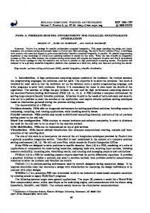
4 Case Study This section demonstrates WorkWays on an aerodynamic design optimization case study, in which human input is used to guide the optimization of a 2D airfoil section [27]. This section first explains the optimization process, and then demonstrates how this process is written into a workflow using WorkWays.
4.1 Optimization Process The optimization process used here is closely based on the experiment described by Kipouros et al. [27]. The new candidate airfoil geometries are generated by local and global modifications using the Free-Form Deformation (FFD) technique [28] (Figure 4). The leading and trailing edges of the airfoil section are kept unchanged to ensure fixed chord length and angle of attack. The parameter space of the optimization problem is defined by the movement of four control points in the Cartesian space, as highlighted in Fig. 3. The open source flow analysis tool Xfoil [29] is used to evaluate each new design vector for the prediction of the lift, drag and moment coefficients. In this example, the combined objective function targets to express maximum lift and minimum drag, subject to a set of hard geometrical constraints of the thickness at 25% and 50% of the chord that maintain the practicality and complexity of this benchmark engineering design case study [27].
Figure 4: FFD with four control points (Modified from [27]).
Once an optimization process is successfully completed, scientists and engineers are interested in identifying the physical and behavioral relationships between design parameters and performance metrics. This is not a trivial task since it involves multi-dimensional data analysis of the parameter space and objective function(s) space simultaneously. In Kipouros et al. [30] a method based on Parallel Coordinates visualization [31] has been introduced for the post-analyses of turbo-machinery compressor blades, and in Kipouros et al. [32] this method has been expanded further for higher order of data dimensionality and human interaction. This technique has been then tested in Hettenhausen et al. [33] and found to be superior over the direct design optimization approaches, in the context of computational engineering design. The knowledge that can be acquired from such analyses can be used to reduce the number of design variables, or reduce the ranges of variability of some of the
2290
The WorkWays problem solving environment
H. Nguyen, D. Abramson and T. Kipouros
design parameters, and ultimately succeed in the reduction of the size of the design space and hence accelerate the design convergence. Furthermore, the domain expert who interacts with such design systems can identify the region of interest of the design parameters that will reveal more interesting and realistic optimum design configurations in shorter time. Hence, a dynamic and interactive relationship should be supported between the human design expert and the computational design system. In the current work, we improve this method by enabling such human-in-the-loop computational design approaches within workflow management frameworks.
4.2 Optimization workflow with WorkWays Figure 5 shows a workflow performing the 2D airfoil optimization. This workflow uses three IO actors: Output and Optimum actors for visualising temporary and optimum shape of the foil, and ParallelCoordinates actor for analyzing relationships between design and object space. All these three IO actors are generated from the generic IOActor. The WorkflowEditorPortlet allows users to modify and experiment the workflow before the full-scale execution. The DefineSearchSpace actor initiates the optimization by defining the domain of the search; in this case, this domain is the combination of possible coordinates of the four control points. The starting points will be selected from this domain by the SelectPointsActor, and will be sent to the optimization actor. This workflow uses the simplex optimization method, other optimization algorithms, for instance Hook-Jeeves, Genetics Algorithm, etc., can be used just by replacing the optimization actor. The optimization actor generates set of points that are sent for evaluation. In this workflow, FFD and Xfoil are combined into one composite actor: Compute xfoil. This composite actor evaluates starting points from the optimization actor, and results of the evaluation are used to decide the next generation of points. This cycle stops when convergence criteria specified in the optimization actor are met. Note that there can exist multiple optimum solutions.
Figure 5: The airfoil workflow (left) being edited in the WorkflowEditorPortlet (right).
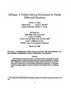
Figure 6 displays the Web page created by WorkWays. The WorkflowEditorPortlet is collapsed to reduce the size of the figure. There are three IOPortlets corresponding to three IOActors in the workflow. These portlets are automatically invoked by WorkWays when the workflow is executing. The visualization on each portlet depends on the IO operation defined by the corresponding IOActor. The two IOPortlets on the right display the temporary and optimum airfoil shapes while the parallel coordinate IOPortlet is shown on the left. This parallel coordinate plot has 9 dimensions, consisting of 4 Cartesian coordinates of the control points, and the evaluation result. In order to guide the optimization to a particular parameter space, the users choose a sub-region of each dimension. Once the user clicks the submit button, this information is sent back to the ParallelCoordiantes actor. This triggers the DefineSearchSpaceActor to generate new set of starting points.
2291
The WorkWays problem solving environment
H. Nguyen, D. Abramson and T. Kipouros
Figure 6: Workflow execution with IOPortlets showing parallel coordinates and 2D airfoil shape.
This example illustrates how WorkWays supports an interactive optimization as a problem-solving environment. An editor based on Kepler GUI is provided to allow users to create, edit and experiment with the workflows. Our solution is flexible and makes it possible to integrate different domain specific tools into the experiments. Here we have shown FFD and xfoil as an example. During the construction of the workflow, the IOActor is used to create actors performing different IO operations. This simplifies the tasks of creating new IO actors since no programming is involved. Once deployed and executed, IOPortlet and the generated IO actors allow users to monitor and steer the running experiment.
5 Conclusions and Future Work In this paper we have presented WorkWays, a workflow-based science gateway capable of supporting man-in-the-loop workflows and potentially computational engineering design processes. We have discussed the WorkWays’ general architecture. We use Kepler as the workflow engine, and JSR 286 standards for Web components. We also discussed the IO framework, which allows users to insert data into, or export data out of a running workflow. The IO framework has a configurable IOActor that can be used to generate new IO actors from simple definition files. This simplifies the creation of new IO actors since no programming is required. WorkWays also provides an intuitive editor that is based on Kepler GUI editor. This is important since it allows users to interact with the workflows through a uniform Web environment. We also discussed the usage of Nimrod toolkit family in the architecture of WorkWays to manage and execute parallel workflows. An optimization study of 2D airfoil section is used to demonstrate the system. There are several improvements we would like to make to our system. First, we would like to enrich the type of objects supported by IO actors and IO portlets. This will allow WorkWays to support more studies in different disciplines. Second, we will improve the way IO operations are defined. The text-based declaration of IO operations is error-prone; a GUI-based approach would be more user-friendly. Third, we will support different types of clients, beside Web client. One of such client is the OptiPortal tiled display wall [34]. This will enable visualization of high-resolution data, which often requires very large screens.
References [1] J. Yu and R. Buyya, “A taxonomy of workflow management systems for grid computing,” Journal of Grid Computing, vol. 3, no. 3–4, p. 29, 2005.
2292
The WorkWays problem solving environment
H. Nguyen, D. Abramson and T. Kipouros
[2] N. Wilkins-Diehr, D. Gannon, G. Klimeck, S. Oster, and S. Pamidighantam, “TeraGrid Science Gateways and Their Impact on Science,” Computer, vol. 41, no. 11, pp. 32–41, 2008. [3] I. Altintas, A. W. Lin, J. Chen, C. Churas, M. Gujral, S. Sun, W. Li, R. Manansala, M. Sedova, J. S. Grethe, and M. Ellisman, “CAMERA 2.0: A Data-centric Metagenomics Community Infrastructure Driven by Scientific Workflows,” 2010 6th World Congress on Services, pp. 352–359, Jul. 2010. [4] M. Christie and S. Marru, “The LEAD Portal: a TeraGrid gateway and application service architecture,” CONCURRENCY AND COMPUTATION, vol. 19, no. 6, pp. 767–781, 2007. [5] E. Afgan, J. Goecks, D. Baker, N. Coraor, and T. Galaxy, “Galaxy - a Gateway to Tools in eScience,” in Guide to e-Science, Computer Communications and Networks, 2011, pp. 145–177. [6] V. Curcin and M. Ghanem, “Scientific workflow systems - can one size fit all?,” 2008 Cairo International Biomedical Engineering Conference, pp. 1–9, Dec. 2008. [7] R. S. Barga, J. Jackson, N. Araujo, D. Guo, N. Gautam, K. Grochow, and E. Lazowska, “Trident: Scientific Workflow Workbench for Oceanography,” 2008 IEEE Congress on Services Part I, pp. 465–466, Jul. 2008. [8] A. Rygg, P. Roe, and O. Wong, “GPFlow: An Intuitive Environment for Web Based Scientific Workflow,” 2006 Fifth International Conference on Grid and Cooperative Computing Workshops, pp. 204–211, 2006. [9] H. Nguyen and D. Abramson, “WorkWays : Interactive Workflow-based Science Gateways,” in 8th IEEE International Conference on e-Science, 2012. [10] P. Romano, E. Bartocci, G. Bertolini, F. De Paoli, D. Marra, G. Mauri, E. Merelli, and L. Milanesi, “Biowep: a workflow enactment portal for bioinformatics applications.,” BMC bioinformatics, vol. 8 Suppl 1, p. S19, Jan. 2007. [11] P. Mates, E. Santos, J. Freire, and T. Silva, “CrowdLabs : Social Analysis and Visualization for the Sciences,” in 23rd international conference on Scientific and statistical database management, 2011, pp. 555–564. [12] G. Singh, E. Deelman, G. Mehta, K. Vahi, M. Su, G. B. Berriman, J. Good, J. C. Jacob, D. S. Katz, A. Lazzarini, K. Blackburn, and S. Koranda, “The Pegasus Portal : Web Based Grid Computing,” in 2005 ACM symposium on Applied computing, 2005, pp. 680–686. [13] W. Wu, T. Uram, M. Wilde, M. Hereld, and M. E. Papka, “Accelerating science gateway development with Web 2.0 and Swift,” Proceedings of the 2010 TeraGrid Conference on - TG ’10, pp. 1–7, 2010. [14] M. A. Nacar, M. E. Pierce, and G. C. Fox, “GTLAB: Grid Tag Libraries Supporting Workflows within Science Gateways,” Semantics, Knowledge and Grid, Third International Conference on. pp. 194–199, 2007. [15] “SciencePipes. http://sciencepipes.org,” 2013. [16] J. Orvis, J. Crabtree, K. Galens, A. Gussman, J. M. Inman, E. Lee, S. Nampally, D. Riley, J. P. Sundaram, V. Felix, B. Whitty, A. Mahurkar, J. Wortman, O. White, and S. V Angiuoli, “Ergatis: a web interface and scalable software system for bioinformatics workflows.,” Bioinformatics (Oxford, England), vol. 26, no. 12, pp. 1488–92, Jun. 2010. [17] J. Goecks, A. Nekrutenko, and J. Taylor, “Galaxy: a comprehensive approach for supporting accessible, reproducible, and transparent computational research in the life sciences.,” Genome biology, vol. 11, no. 8, p. R86, Jan. 2010. [18] D. Blankenberg, G. Von Kuster, N. Coraor, G. Ananda, R. Lazarus, M. Mangan, A. Nekrutenko, and J. Taylor, “Galaxy: a web-based genome analysis tool for experimentalists.,” Current protocols in molecular biology, vol. Chapter 19, no. January, p. Unit 19.10.1–21, Jan. 2010. [19] S. G. Parker and C. R. Johnson, “SCIRun : A Scientific Programming Environment for Computational Steering,” in SC’95: Proceedings of the 1995 ACM/IEEE conference on Supercomputing, 1995, 1995, pp. 1–20.
2293
The WorkWays problem solving environment
H. Nguyen, D. Abramson and T. Kipouros
[20] S. Graphics and C. Systems, “IRIS Explorer : A Framework for Investigation,” ACM SIGGGRAPH Computer Graphics, vol. 29, no. 2, pp. 13–16. [21] D. Abramson, C. Enticott, and I. Altintas, “Nimrod / K : Towards Massively Parallel Dynamic Grid Workflows Grid Programming in Kepler,” in SC’08: Proceedings of the 2008 ACM/IEEE conference on Supercomputing, 2008, no. November, pp. 1–11. [22] “nodejs. http://nodejs.org,” 2013. [23] “MongoDB.http://www.mongodb.org,” 2014. [24] “Vaadin Java Framework. https://vaadin.com,” 2013. [25] “Kepler Web UI. https://kepler-project.org/developers/interest-groups/webui,” 2014. [26] “NeCTAR. http://www.nectar.org.au,” 2014. [27] T. Kipouros, T. Peachey, D. Abramson, and A. M. Savill, “Enhancing and Developing the Practical Optimization Capabilities and Intelligence of Automatic Design Software,” in 53rd AIAA/ASME/ASCE/AHS/ASC Structures, Structural Dynamics and Materials Conference, 2012, pp. 1–7. [28] T. W.Sederberg and S. R.Parry, “Free-Form Deformation of Solid Geometric Models,” SIGGRAPH, vol. 20, pp. 151–160, 1986. [29] M. Drela, “XFOIL: An Analysis and Design System for Low Reynolds Number Airfoils,” in Low Reynolds Number Aerodynamics, 1989, pp. 1–12. [30] T. Kipouros, M. Mleczko, and A. M. Savill, “Use of Parallel Coordinates for Post-Analyses of Multi-Objective Aerodynamic Design Optimisation in Turbomachinery,” in AIAA Multidisciplinary Design Optimization Specialists, AIAA-2008-2138, 2008. [31] A. Inselberg, Parallel Coordinates: Visual Multidimensional Geometry and Its Applications. 2009. [32] T. Kipouros, A. Inselberg, G. Parks, and A. M. Savill, “Parallel Coordinates in Computational Engineering Design,” AIAA Multidisciplinary Design Optimization Specialists, vol. 1750, pp. 1–11, Apr. 2013. [33] J. Hettenhausen, A. Lewis, M. Randall, and T. Kipouros, “Interactive multi-objective particle swarm optimisation using decision space interaction,” IEEE Congress on Evolutionary Computation, vol. 1350, pp. 3411–3418, Jun. 2013. [34] A. T. A. Defanti, J. Leigh, L. Renambot, B. Jeong, Q. Liu, M. Katz, P. Papadopoulos, and J. Keefe, “The OptIPortal , a Scalable Visualization , Storage , and Computing Termination Device for High Bandwidth Campus Bridging,” Future Generation Computer Systems, vol. 25, no. 2, pp. 114– 123, 2009.
2294