speed range can be achieved by flux weakening of the current vector control [1,2]. Because of these advantages, IPMSM is widely used in many area; home ...
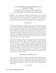
Thermal Equivalent Circuit Network for Outer Rotor Type Motors K S Kim, H J Kim, J P Hong Department of Automotive Engineering, Hanyang University, Seoul 133-791, Korea Keywords: convection, conduction, thermal equivalent circuit, thermal test
T1
Abstract r2
In the industry and military field, hydraulics is substituted by motor. In contrast with automotive and home appliance, this motor required various torque level. The test motor operates under low speed and high torque. Because this motor needed high armature current and armature is located in near shaft in the outer rotor type, this is disadvantage than inner rotor type in the radiant. In this paper, the thermal analysis is conducted by thermal equivalent circuit, analysis is compared with test.
T4
L 2
r1 T2
L
T3 Figure 1: Equivalent cylindrical shape.
model
of
motor
considering
equivalence and solving time is very short than CFD. In addition, difference between test and analysis value is very small. Therefore, using thermal equivalent circuit network, outer rotor type motor is analyzed.
1 Introduction Interest in interior permanent magnet synchronous motors (IPMSM) has been growing because high torque and a wide speed range can be achieved by flux weakening of the current vector control [1,2]. Because of these advantages, IPMSM is widely used in many area; home application, automotive engineering, and military etc. In the IPMSM, several considerations exist by a material as a necessity. For example, thermal problem is critical consideration which is influenced by the heat source. In the operation, losses which contain copper loss, core loss, and eddy current loss in the permanent magnet is generated. These losses are increase without method of radiant heat, electric breakdown and irreversible demagnetization are generated in winding and permanent magnet. In addition, desired life time decreases. For preventing negative effect and determining the maximum rating, thermal analysis is necessary. In the outer rotor type motor, stator is located in near shaft. If the motor operates in the low speed and high torque, copper loss is larger than core loss. In this case, copper loss which is generated in the stator winding is influence the motor temperature. Therefore, thermal analysis and estimation is essential in the outer rotor type motor [3]. In this paper for estimation of thermal temperature, thermal equivalent circuit network is adopted. The equivalent circuit has several advantage comparing the computational fluid dynamics (CFD). The thermal circuit is easy to analysis because equivalent model mathematically concise,
2 Component of thermal equivalent circuit Thermal equivalent circuit network is composed of several parameter; thermal resistance, heat source, thermal capacitance. The thermal resistance is divide by conduction and conduction. The heat source is loss which is generated to core, coil, and permanent magnet. The thermal capacitance is the capacity. In this chapter, these parameters are dealt with in detail. 2.1 Thermal resistance of the conduction When the heat due to motor loss is applied to each part, the conduction is generated. Because the coefficient is larger than convection, this heat transfer is more rapid than convection. This resistance is easy to design if motor is divided to several part. The core is divided to radial direction and axial direction. The thermal resistance is obtained by Rcond
l kA
(1)
where k is coefficient of conductive heat transfer, A is the area through the heat, l is the length. This is base equation for obtaining the each direction. Fig.2 shows the modeling of the mal resistance at yoke. In the radial direction, (2) and (3) are
1
T1 L/2
R1
Stator yoke
T3
R3 R a
T4
R4 R m
Tm RR2
r2 r1
T2
Figure 3: Calculation process of core loss.
Figure 2: Modeling of thermal resistance at yoke.
If heat is applied to fluid when a fluid is some surface or atmosphere, the fluids flow the surface due to difference of density. This is called natural convection. On the surface, motor temperature is increased, difference of density between high and low level is occurred. On the other hand, forced convection is caused by rotating rotor in the air gap. The natural and forced convection is determined by Taylor number (Ta) which is dimensionless number. (6) is Nusselt number (Nu) according to Ta [6].
applied, (4) is applied to axial direction. In the lumped parameter method, (5) is the compensating resistance between mean and peak temperature [4,5]. R3
1 2S k r Ls
ª § 2 § r1 «1 � ¨¨ 2 r2 ln ¨ «¬ © © r2
º ·· 2 2 ¸ ¸¸ / � r1 � r2 » »¼ ¹¹
(2)
R4
1 2S k r Ls
ª § 2 § r1 « ¨¨ 2 r1 ln ¨ «¬ © © r2
º ·· 2 2 ¸ ¸¸ / � r1 � r2 � 1» »¼ ¹¹
(3)
R1
L 6S k a ( r12 � r2 2 )
R2
�1 4S k r Ls ( r12 � r2 2 )
(4)
ª § §r « r12 � r2 2 � ¨¨ 4 r12 r2 2 ln ¨ 1 «¬ © r2 ©
Nu 2 (Ta � 1700) ° 2 2 0.367 , (1700 � Ta 2 / Fg2 � 104 ) ® Nu 0.128(Ta / Fg ) ° Nu 0.409(Ta 2 / F 2 )0.241 (104 � Ta 2 / F 2 � 107 ) g g ¯
(5)
º ·· 2 2 ¸ ¸¸ / � r1 � r2 » »¼ ¹¹
On the housing, natural convection is occurred by motor loss. For obtaining the coefficient of natural convection, Nu must be determined. The calculation of Nu can be computed by the equation related to Rayleigh number (Ra) and Prantle number (Pr).
where each length is shown to fig.2, ka and kr is thermal conductivities; the axial and radial. The core and magnet is described by these equation, on the other hand, coil and complex shape is described according to thermal flow. 2.2 Thermal resistance of the convection
Nu
The convection is caused in the air gap and housing surface. �4QVQT
�/CIPGV
+
½ 0.387 Ra1/6 ° ° D ®0.60 � ¾ 9/16 8/27 ª º 1 � (0.559 / Pr) ¬ ¼ ¿° ¯°
�#KT�ICR
R10
R11 R9
R6
R18
R33
R34
R4
R14
R12
R15
R17
R3
R7
R23
R24
R48
R46
R37
R19
R20
C1
R47
R41
R36
R32
R13 R1
R42 R44
R40
R8
R2
(7)
�5VCVQT
R43 R5
2
R16
-
Vroom air
(6)
R31
R35
R38
R49 R45
R39
R21 R30
R25
R26
R29
R28
R27
R22 C2
C5
R48
C4 C3
Figure 4: The configuration of the equivalent thermal circuit.
2
C6
C7
C8
C9
C10
flow. Therefore, resistance of convective heat transfer is derived by
PM & flux barrier
Rconv
1 hA
(9)
where A is area to air flow. Before
2.3 Heat source
After
Shape of slot
In the motor, heat source is composed by the copper loss, the core loss. The copper loss is winding loss which current flow through. The core loss is calculated by FEM, and fig. 3 shows the calculation process of core loss [7,8]. 2.4 Thermal capacitance Thermal capacity is necessary quantity which rise the 1oC of the temperature of matter. This is expressed by Test motor
Cm
Figure 6: Test motor for thermal analysis. Unit VDC Arms Nm kW rpm
Pole / Slot DC link voltage Current limit Max. torque Output power Max. speed Operating temperature
o
3 Thermal equivalent circuit The thermal equivalent circuit network is shown in Fig. 4. This circuit is composed to resistance, heat source, and capacitance. Linear differential equation for the node i can be derived as expressed in (11) [6].
-10 ~ 60
Ci
Table 1: Specification of test motor.
Core Housing Coil PM
Thermal conductivity
Specific heat
(W/mŘoC) 49.8 49.8 394.0 9.0
(J/kgŘoC) 502 486 486 440
7850 7850 8960 7650
1 (T j � Ti ) � gi R ji
(11)
4 Thermal analysis and result 4.1 Analysis model Fig. 5 shows the analysis model which is composed equivalence model, left side is convert to right side. The test motor is 32pole/36slot. Table 1 shows the specification of test motor. The motor operated in 1000Nm and 14.3rpm. The material data is shown table 2.
Nu is computed by equation according to the type of thermal flow between natural and forced convection. Coefficient of convective heat transfer is obtained by Nu k L
dTi dt
where Ci is the ith node thermal capacitance, Ti is the ith node temperature, Rji is thermal resistance between two adjacent nodes, i and j, and gi is heat generation at node i.
Density (kg/m3)
Table 2: Material specification.
h
(10)
where Cm is thermal capacitance, ȡm is density, Vm is each motor volume, and c is specific heat of material.
Value 32 / 36 680 1000 1570 14.3
C
U mVm c
(8)
4.2 Analysis and test result The test is conducted under the 800Nm and 14.3rpm. This operating point is high torque and low speed, copper loss is very larger than core loss and eddy current loss of PM. Table
where h is coefficient of heat transfer, k is coefficient of conductive heat transfer, and L is area according to air
3
160 140 o
Temperature[ C]
5 Conclusion
Exp_Phase_U Exp_Phase_V Exp_Phase_W Exp_Yoke_1 Exp_Yoke_2 Sim_Stator_yoke Sim_End_winding
120
In this paper, temperature is estimated by using thermal equivalent circuit network. The parameter is obtained to dimensionless number and thermal equation. The thermal circuit is composed by equivalent thermal parameter. According to thermal test, thermal circuit is verified. Therefore, this circuit is can be an effective method to predict the motor temperature in the initial design.
100 80 60 40
0
5
10
15 20 Time[min.]
25
Acknowledgements
30
This research was supported by the MSIP(Ministry of Science, ICT&Future Planning), Korea, under the CITRC(Convergence Information Technology Research Center) support program (NIPA-2013-H0401-13-1008) supervised by the NIPA(National IT Industry Promotion Agency)
Figure 7: Analysis and test result @ 14.3rpm.
Copper loss Value (W)
1314.0
Core loss Yoke
Teeth
Rotor
3.8
2.4
1.2
References
[1] C. Feng, P. Yulong, L. Xinmei, G. Bin, and C. Shukang, “The Performance Research of Starter-Generator Based on Reluctance Torque Used in HEV,” IEEE Trans. on Magn., volume 45, no.1, pp. 635–638, (2009). Analysis (oC) Test (oC) Error(%) [2] J. Hur and B. W. Kim, “Rotor Shape Design of an Interior PM Type BLDC Motor for Improving End winding 143.0 145.8 1.0 Mechanical Vibration and EMI Characteristics,” JEET, volume 5, no. 3, pp.462-467, (2010). Stator yoke 79.9 84.8 6.1 [3] V. Gnielinski, “New Equations for Heat and Mass Transfer in Turbulent Pipe and Channel Flow,” American Table 4: Analysis and test result Institute of Chemical Engineer, volume 16, no. 3, pp. 359-368, (1961). 3 shows the loss of motor. This value cause the temperature [4] Y. A. Cengel, Heat transfer: A practical approach, 2nd rising. ed., McGraw-Hill, (2003). The computed value of heat transfer coefficient is 20.1 W/m2Ř [5] P. H. Mellor, D. R. Roberts, D. Turner, “Lumped o C in the surface and 26.3 W/m2ŘoC in the air gap. These Parameter Thermal Model For Electrical Machines of TEFC Design,” IEE, volume 138, no. 5, (1991). values are calculated by (6)-(8). The value in the air gap is low because motor is very low speed in the forced convection. [6] B. H. Lee, K. S. Kim, J. W. Jung, J. P. Hong, and Y. K. Kim, “Temperature estimation of IPMSM using thermal Fig. 6 shows the test motor. The thermocouple is attached in equivalent circuit,” IEEE Trans. on Magn., volume 48, end winding which is the hottest point, because the radiant no.11, pp. 2949–2952, (2012). heat is very low than stator winding. The heat of end winding is radiant by air which is low value. On the other hand, heat [7] S. Adhikari, S. K. Halgamuge, and H. C. Watson, “An Online Power-Balancing Strategy for a Parallel Hybrid of stator winding is radiant by core in shape of conduction. Electric Vehicle Assisted by an Integrated Starter Fig. 7 and table 4 show the analysis and test result at 14.3rpm. Generator,” IEEE Trans. on Vehicular Technology, The mean temperature of end winding, hottest point, rises at o o volume 59, no.6, pp. 2689–2699, (2010). 145.8 C in the test. The analysis result is 143.0 C. The error [8] B. H. Lee, S. O Kwon, T. Sun, J. P. Hong, G. H. Lee, J. between analysis and test is 6%. In addition the temperature Hur, “Modeling of Core Loss Resistance for d-q curve is analogous in the changing of the time. These low Equivalent Circuit Analysis of IPMSM considering error is cause by very low speed. In the high speed, the Harmonic Linkage Flux,” IEEE Trans. on Magn., coefficient of convective heat transfer is difficult. In general, volume 47, no.5, pp. 1066-1069, May, (2011). the error of this thermal equivalent circuit network 10-15%. Table 3: Value of the heat source @14.3rpm.
4