Apr 15, 2006 - corrugated structures derived in spectral domain. The numerical ... amplification of DFB-type gain-clamped SOAs are simulated and analyzed.
932
IEEE PHOTONICS TECHNOLOGY LETTERS, VOL. 18, NO. 8, APRIL 15, 2006
Time and Spectral Domain Properties of Distributed-Feedback-Type Gain-Clamped Semiconductor Optical Amplifiers G.-X. Chen, W. Li, C.-L. Xu, W.-P. Huang, and S.-S. Jian
Abstract—A comprehensive model for the analysis of distributed-feedback (DFB)-type semiconductor optical amplifiers (SOAs) both in time- and frequency-domain is developed by combination of a wideband field-based traveling-wave rate equation model and an extended transfer matrix formalism for corrugated structures derived in spectral domain. The numerical implementation of the model is successfully fulfilled by dividing the device into many short segments along the cavity length. Based on this unique model, some time- and spectral-domain properties, such as amplified spontaneous emission, laser action, and signal amplification of DFB-type gain-clamped SOAs are simulated and analyzed. Index Terms—Amplified spontaneous emission (ASE), extended transfer matrix, laser diodes (LDs), semiconductor optical amplifiers (SOAs), traveling-wave model.
I. INTRODUCTION
combining a wideband field-based traveling-wave model and an extended transfer matrix formalism derived in spectral domain for corrugated structures. The model considers the random amplified spontaneous emission (ASE) fields, the lasing field, and the input optical signal fields in a general frame. Both time- and frequency-domain behaviors of DFB GC-SOAs can be obtained in very details. As typical applications, some time- and spectral-domain properties of an InGaAsP–InP DFB GC-SOA are simulated. II. TIME-DOMAIN DYNAMIC MODEL To account for the wideband ASE fields, a set of coupled traveling-wave equations for the forward and backward propagating optical fields in the cavity of the device under consideration can be derived as [3]
I
N PAST years, semiconductor optical amplifiers (SOAs) have found many applications in optical signal processing and integrated functional devices. A great effort has been made in the development of theoretical models and simulation tools for SOA performance evaluation and design. To reduce intermodulation distortion in conventional SOAs, various gain-clamping (GC) schemes have been used in SOA design [1]. In such devices, the cavity gain is clamped by an out-of-band laser action to it’s threshold value. The steady-state and time-domain performance of a distributed Bragg reflector or vertical-laser-type GC-SOA can be analyzed using an intensity or photon density-based rate equation model [1], and the detailed wideband spectral information can be obtained using the extended transfer matrix formalism derived by Boucher and Sharaiha [2]. However, for the simulation of distributed-feedback (DFB)-type GC-SOAs, a comprehensive wideband field-based traveling-wave rate equation model has to be used, and the spectral domain extended transfer matrix formalism for DFB active structures needs to be derived. In this letter, a theoretical model for the simulation of DFB GC-SOAs with complex longitudinal structures is developed by
Manuscript received November 8, 2005; revised January 11, 2006. This work was supported by the Science and Technology Foundation of Beijing Jiaotong University (2005SZ004 and 2003RC063) and by the Nature Science Foundation of China (Projects 60577021 and 60437010). G.-X. Chen and S.-S. Jian are with Institute of Lightwave Technology, Beijing Jiaotong University, Beijing 100044, China. W. Li is with Department of Chemical and Engineering Physics, University of Wisconsin-Platteville, Platteville, WI 53818 USA. C.-L. Xu and W.-P. Huang are with Department of Electrical and Computer Engineering, McMaster University, Hamilton, ON L8S 4K1, Canada. Digital Object Identifier 10.1109/LPT.2006.872276
(1)
(2) and are the slowly varying amplitudes of the th where forward and backward propagating components, respectively. and are the group velocity, material gain, and phase detuning of the th component, respectively. is the nonlinear gain suppression factor, and the photon density. is the coupling coefficient between the forward and backward propagais the internal loss, is the optical confinement tion waves, and are the spontaneous emission term confactor. tributed to the th forward and backward propagation components, respectively. The boundary conditions are set as follows (assumed no input field at the right facet):
(3) where and are the amplitude reflection coefficients at the is the input signal field at frequency left and right facets. of the th component. The above boundary conditions insure that the effects of multipass gain on the signal amplifications are considered in present model.
1041-1135/$20.00 © 2006 IEEE
CHEN et al.: TIME AND SPECTRAL DOMAIN PROPERTIES OF DFB-TYPE GAIN-CLAMPED SOAs
933
The stochastic property of and is described by a random process with zero mean value and correlation functions as described in [4]. The carrier density within the active medium is coupled with the traveling-wave field equations through the stimulated emission process, and obeys the following rate equation:
(4) where is the bias current, the injection efficient, the elecand are tron charge, the volume of active region, and the material recombination coefficients. The numerical implementation of the above dynamic model was successfully fulfilled by dividing the device into a number of short segments and assuming that both the injection curand the carrier density are uniform within subsecrent . An effective uniform photon dention is also assumed for subsection . Then the wideband sity coupled-wave equations are solved consistently with the carrier rate equation by extending the split-step method [5] to multilongitudinal-mode coupled traveling-wave equations [3]. The time-varying properties of the devices, such as the forward and backward output fields and the field distribution along the cavity length for each longitudinal component, and the carrier density distribution profile, can be readily obtained at any instant time using the above procedure. III. EXTENDED TRANSFER MATRIX FORMALISM For a given carrier density distribution, the detailed output ASE power spectrum of the device, expressed in [W Hz ] can be calculated by following extended transfer matrix formalism, which was derived in spectral-domain by following the same steps as that being used in [2] for Fabry–Pérot (FP) active structures:
(5) is the spontaneous emission power per unit frewhere quency interval per unit cavity length within subsection , and Hz ], which is calculated in quite simexpressed in [W m ilar a manner as that used in [3] for the spontaneous emission is the net optical gain in subsection . power calculation. and are the transfer matrix of the whole cavity structure and the left partial transfer matrix of the th subsection, a straightforward calculation leads to (6)
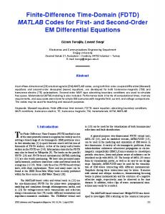
Fig. 1. Simulated output spectra of an SCH-MQW DFB LD with structure described in [6]. The injected current is 70 mA.
where and are the transfer matrices of the left and is the transfer matrix of the th right facet, respectively. subsection and deduced to (7), as shown at the bottom of the page, with . and are grating period and carrier induced index change in section . Once the transfer matrix of the whole structure is obtained, the overall output spectrum at the right facet can be calculated by
(8) and are the spectra of the forward and where backward input signals, respectively. In the present work, we . assumed IV. SIMULATION RESULTS AND DISCUSSION Based on the above theoretical and numerical models, almost all the important time- and spectral-domain properties of GC-SOAs with complex cavity structures can be simulated. The validity of the model is performed by comparing the calculated results with published experimental data. Fig. 1 shows a calculated spectrum of a 1550-nm InGaAsP–InP separate-confinement-heterostructure multiple quantum-well (SCH-MQW) DFB laser described in [6]. The bias current is 70 mA. The band structures of the strained SCH-MQW are calculated using the theory and 4 4 Pikus–Bir Hamiltonian, then the material gain and spontaneous emission spectra are obtained for given carrier densities. The result shown in Fig. 1 is in good agreement with the measured spectrum given in [6]. For the sake of illustration, we further consider a bulk InGaAsP–InP DFB-type GC-SOA working around 1550 nm . The numerical values taken in with our simulations are as follows: the volume of active region m is 200 0.13 3 m s m s m s m , and the bandgap eV. All other values were taken from [7]. energy is
(7)
934
IEEE PHOTONICS TECHNOLOGY LETTERS, VOL. 18, NO. 8, APRIL 15, 2006
Fig. 2. Simulated output spectra of a DFB LD with antireflection-coated facets operated (a) above and (b) below its threshold current.
Fig. 4. Calculated time-domain results for the total optical power emitted from (a) the left and (b) right facets, respectively. The fluctuation of the total gain at the signal wavelength is given in (c). The operating condition is the same as Fig. 2.
Fig. 3. Amplification of 2.5-Gb/s pseudorandom binary sequence nonreturn-to-zero signal with 10-dBm input power. The bandwidth of the output filter is 1 nm.
0
The spectra of material gain and spontaneous emission rate for a given carrier density are calculated using the density-matrix approach [8] and the carrier induced refractive index change is obtained by Kramers–Kronig transformation using the calculated material gain spectrum. Fig. 2(a) and (b) shows the calculated output spectra of the DFB GC-SOA biased above and below its lasing threshold without input signals. Fig. 3 gives the simulation results of signal amplification with a 1-nm optial filter added to the SOA output, which shows that the gain saturation effect is eliminated by the lasing action. During the signal amplification, the device must be biased well above the lasing threshold and the input signals can suppress the lasing action considerably, but the gain will be sustained to its threshold value unless the laser is extinguished by the signals. The calculated total optical power (laser together with ASE and signals) emitted from the left and right facets are given in Fig. 4(a) and (b), respectively. The relaxation oscillation of the lasing mode is clearly shown, especially for the left side output, in which the lasing mode is dominant. The results imply that a GC-SOA can simultaneously perform co- and antidirectional wavelength conversion without the need for external DC input. It should be noted in Fig. 3 that the noise levels are different for “0” and “1” bits. This is due to the rearrangement of the photons and carrier densities along the cavity when input level changed. So the gain cannot be perfectly clamped during dynamic operation, as shown in Fig. 4(c). Fig. 5 shows the calculated output spectra of the wideband ASE, amplified signal, together with the laser field. The ripple away from the lasing mode comes from the FP effects induced by the residual facet reflectivity. From Figs. 2 and 5, one can see that the ASE ripple is much smaller than that of traditional SOAs with the same facet reflectivity values and the ASE is clamped to it’s threshold level.
Fig. 5. Output spectra of the ASE, amplified signal, and the laser of the DFB-GC-SOA. The operating condition is the same as Fig. 3.
V. CONCLUSION A wideband field-based dynamic model for DFB-type GC-SOAs has been proposed, and an extended transfer matrix formalism for corrugated active structures is derived in spectral domain. The model can easily be extended to any kind of LDs, SOAs, and their integrations. Both time and spectral domain properties of the devices can be calculated in great detail. REFERENCES [1] C.-Y. Jin, Y.-Z. Huang, L.-J. Yu, and S.-L. Deng, “Detailed model and investigation of gain saturation and carrier spatial hole burning for a semiconductor optical amplifier with gain clamping by a vertical laser field,” IEEE J. Quantum Electron., vol. 40, no. 5, pp. 513–518, May 2004. [2] Y. Boucher and A. Sharaiha, “Spectral properties of amplified spontaneous emission in semiconductor optical amplifiers,” IEEE J. Quantum Electron., vol. 36, no. 6, pp. 708–720, Jun. 2000. [3] G.-X. Chen, W. Li, W.-P. Huang, and S.-S. Jian, “An advanced dynamic model for semiconductor optical amplifiers and laser diodes,” Chin. Phys. Lett., vol. 22, pp. 110–113, Jan. 2005. [4] G. C. Dente and M. L. Tilton, “Modeling multiple-longitidinal-mode dynamics in semiconductor lasers,” IEEE J. Quantum Electron., vol. 34, no. 2, pp. 325–335, Feb. 1998. [5] B.-S. Kim, Y. Chung, and J.-S. Lee, “An efficient split-step time-domain dynamic modeling of DFB/DBR laser diodes,” IEEE J. Quantum Electron., vol. 36, no. 7, pp. 787–794, Jul. 2000. [6] C. Park, J. S. Kim, D. K. Oh, D. H. Jang, C. Y. Park, J. H. Ahn, H. M. Kim, H. R. Choo, H. Kim, and K. E. Pyun, “Low threshold losscoupled laser diode by new grating fabrication technique,” IEEE Photon. Technol. Lett., vol. 9, no. 1, pp. 22–24, Jan. 1997. [7] S. L. Chuang, Physics of Optoelectronic Devices. New York: Wiley, 1995. [8] G. P. Agrawal and N. K. Dutta, Long-Wavelength Smiconductor Lasers. New York: Van Nostrand Reinhold, 1986.