Mar 28, 2011 - Schollwöck's, from his talk at IPAM, UCLA, at https://www.ipam.ucla.edu/publications/qs2009/ · qs2009_8384.pdf. [45] Pthreads or POSIX ...
Time Evolution with the DMRG Algorithm: A Generic Implementation for Strongly Correlated Electronic Systems G. Alvarez,1 Luis G. G. V. Dias da Silva,2 E. Ponce,3 and E. Dagotto4
arXiv:1103.5391v1 [cond-mat.str-el] 28 Mar 2011
1
Computer Science & Mathematics Division and Center for Nanophase Materials Sciences, Oak Ridge National Laboratory, Oak Ridge, TN 37831, USA 2 Instituto de F´ısica, Universidade de S˜ ao Paulo, C.P. 66318, S˜ ao Paulo, SP, Brazil, 05315-970. 3 Electrical & Computer Engineering and Computer Science Department, Polytechnic University of Puerto Rico, San Juan, PR 00919, USA 4 Department of Physics and Astronomy, University of Tennessee, Knoxville, Tennessee 37996, USA, and Materials Science and Technology Division, Oak Ridge National Laboratory, Oak Ridge, Tennessee 37831, USA (Dated: March 29, 2011) A detailed description of the time-step-targetting time evolution method within the DMRG algorithm is presented. The focus of this publication is on the implementation of the algorithm, and on its generic application. The case of one-site excitations within a Hubbard model is analyzed as a test for the algorithm, using open chains and two-leg ladder geometries. The accuracy of the procedure in the case of the recently discussed holon-doublon photo excitations of Mott insulators is also analyzed. Performance and parallelization issues are discussed. In addition, the full open-source code is provided as supplementary material. PACS numbers: 02.70.-c,05.60.Gg Keywords: DMRG,time evolution,time-step targetting
I.
INTRODUCTION
The accurate calculation of time-dependent quantum observables in correlated electron systems is crucial to achieve further progress in this field of research, where the vast majority of the computational efforts in the past have mainly focused on time-independent quantities. This issue lies at the core of the study of a broad array of physical phenomena in transition metal oxides and nanostructures such as electronic transport, optical excitations, and nonequilibrium dynamics in general. Accurate studies of time-dependent properties will advance the fields of spintronics, low dimensional correlated systems, and possibly quantum computing as well. For a list of recent efforts on these topics by our group, and concomitant set of references for the benefit of the readers, see [1–5] and references therein. The purpose of this paper is to present an explicit implementation of the time evolution within the density matrix renormalization group (DMRG) method [6, 7]. Knowledge of the widely discussed DMRG algorithm to compute static observables is here assumed. Readers not familiar with the method are referred to published reviews [8–11], and to the original publications [6, 7] for further information. Our main focus here is to provide a detailed description of the implementation of the time-step targetting [12] algorithm, and the discussion of a few applications. We also provide full open-source codes and additional documentation to use those codes.[43]
The present work builds upon considerable previous efforts by other groups. In particular, we will mainly follow Manmana et al. in Ref. [13]. The time-step targetting procedure was also reviewed in Ref. [14]. Since it would not be practical to describe in a short paragraph the considerable progress achieved in this field of research in recent years, the interested reader is encouraged to consult the aforementioned reviews along with, e.g., Ref. [15], for a historical account of the development of the methods used in the present publication. Since our aim is to discuss a generic method applicable to any Hamiltonian and lattice geometry, here we do not discuss or implement the Suzuki-Trotter method [16, 17], but focus instead only on the Krylov method [18] for the time evolution, as described in Ref. [13]. Because its implementation can be isolated, the Krylov method can be applied in a generic way to most models and geometries without changes, which is not the case for other methods, such as the Suzuki-Trotter method. The readers interested in the Suzuki-Trotter method should consult the ALPS project [19], where the time evolving block decimation is implemented [16]. Our goal is to compute observables of the form hφ1 |eiHt A0,π(0) A1,π(1) · · · Aa−1,π(a−1) e−iHt |φ2 i.
(1)
where |φ1 i and |φ2 i denote generic quantum many-body states. This category of observables is sufficiently broad to encompass most time-dependent correlations, as represented by a number a of local operators A0,π(0) A1,π(1) · · ·
2 Aa−1,π(a−1) acting on sites π(0), π(1), π(a − 1) of a finite lattice, where π(i) denotes the lattice site on which the operator Ai,π(i) acts, and the extra index i indicates that the operator can be different at each site. An immediate application of this formalism and code is the study of the evolution of a system that is brought out of equilibrium by a sudden excitation. This sudden excitation can be simulated by the state of the system given by the vectors |φ1 i and |φ2 i. Depending on the problem, sometimes it is more convenient to assume that the states remain unchanged but that it is the Hamiltonian H(t) that changes with time. Another application entails the computation of time-dependent properties of systems in equilibrium, such as the Green’s function Gij (t). The organization of this paper is the following. Section II explains in detail the Krylov method for time evolution within the DMRG algorithm, focusing on its implementation. Section III A applies the method to the case of one-site excitations, showing a simple picture of the accuracy of the method. Section III B extends to two-leg ladder geometries the results obtained using tight-binding chains, employing holon-doublon excitations for the specific study. Performance issues are studied in Sec. IV, while Sec. V summarizes our results. The first two appendices contain derivations of exact results used in the paper. The last appendix explains briefly the use of the code, and points to its documentation.
II. A.
METHOD AND IMPLEMENTATION
Lanczos Computation of the Unitary Evolution
To carry out the previously described program [44] of computing observables of the type given by Eq. (1), the first goal is to calculate |φ(t)i ≡ exp(iHt)|φi. The Lanczos technique [20] provides a method to tridiagonalize H into V † T V , where T is tridiagonal and V is the matrix of Lanczos vectors. If the number of those Lanczos vectors is nl , and the Hilbert space for |φi has size n, then T is a square matrix of size nl × nl , and V is, in general, a rectangular matrix of size nl × n. V † T V cannot be used everywhere as a substitution for H, without inducing large errors. But if we start the Lanczos procedure [21] with the vector |φi (instead of using a random vector as is most frequently done), then we can use that substitution accurately in the multiplication H|φi. However, this is not enough here, because we need to compute the exponential of H. For this purpose, it has been shown [22–24] that |φ(t)i ≈ V † exp(iT t)V |φi with an accuracy that increases as time t decreases for fixed nl . We will assume that we have taken t small enough such
that we can regard the expression above to have the accuracy of the Lanczos technique, which is usually high. In other words, if t is small enough, we will assume that using V † exp(iT t)V |φi as a replacement for exp(iHt)|φi is not worse than using V † T V |φi as a replacement for H|φi. This will be enough for our purposes, but for details on the scaling and bounds of the errors made in each case as a function of t and nl , see, e.g., Refs. [22, 23]. Since we started the P Lanczos recursive procedure with the vector |φi, then j Vj 0 ,j |φij ∝ δj 0 ,0 . Finally, we need to diagonalize T = S † DS into a nl × nl diagonal matrix D with diagonal elements dl0 . This last step is not computationally expensive, since T is a nl × nl matrix, as was noted before. Putting it all together, we arrive to |φ(t)ii =
X
† † † idl0 t Vi,k Tk,k Sl0 ,l Tl,0 V0,j |φij , (2) 0 Sk 0 ,l0 e
k,k0 ,l,l0 ,j
for small times t, where the equal sign should be understood to be valid within the accuracy of the Lanczos technique [24]. How to deal with larger times t will be explained in section II C.
B.
Targetting States with the DMRG Algorithm
It appears that now we could use Eq. (2) to compute |φ1 (t)i from some vector |φ1 i, and likewise |φ2 (t)i starting from some vector |φ2 i. Then we would just apply the operators A0,π(0) A1,π(1) · · · Aa−1,π(a−1) to those states within a DMRG procedure, to achieve our aim of computing Eq. (1). But the DMRG algorithm is not immediately applicable to arbitrary states, such as |φ1 (t)i, and was originally developed to compute the ground state of the Hamiltonian instead. This difficulty has been successfully overcome (see [9] and references therein) by redefining the reduced density matrix of the left block L as: XX ρL ωl Φ† (l)α,β Φ(l)α0 ,β , (3) α,α0 = β∈R
l
where α and α0 label states in the left block L, β those of the right block R, and {Φ(l)}l is a set of, as of yet, unspecified states of the superblock L ∪ R. The states Φ(l) are said to be targetted by the DMRG algorithm. Because of their inclusion in the reduced density matrix, these states will be obtained with a precision that scales similarly to the precision of the ground state in the static formulation of the DMRG. The relevance of the weights ωl appearing in Eq. (3) will be discussed in section II C.
3 Which are the states Φ(l) that need to be included in Eq. (3) to compute Eq. (1)? |φ1 (t)i and |φ2 (t)i are certainly needed. Since observables that include the ground state are ubiquitous, the ground state of the Hamiltonian needs to be targetted as well in most cases. But additional states need to be included in order to evolve to larger times, as we will now explain. Our implementation follows the time-step targetting procedure of Ref. [14]. We now introduce a small time τ such that, for all t ≤ τ , Eq. (2) is accurate in the sense defined in, e.g., Ref. [22]. We consider a set of nv times {tx }x , x = 0, 1, · · · nv − 1, such that tx < tx+1 , t0 = 0, and tnv −1 = τ . For simplicity, we assume from now on that |φ1 i = |φ2 i ≡ |φi in Eq. (1). The state |φi is defined by the particular physics problem under investigation and we will consider particular examples in section III. States |φ(tx )i for each 0 ≤ x < nv can be obtained accurately from |φi by using Eq. (2) since tx ≤ τ . To compute Eq. (1) for all t ≤ τ , we target the nv states |φ(tx )i and the ground state |ψi as well. At this point it is instructive to consider a concrete class of states |φi. In a large class of problems these states are related to the ground state |ψi of the Hamiltonian by |φi = Bb−1,π0 (b−1) · · · B1,π0 (1) B0,π0 (0) |ψi,
1
2
3
4
5
6
7
8
1
2
3
4
5
6
7
8
1
2
3
4
5
6
7
8
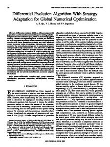
B4 |ψ> B7 B4 |ψ> B3 B7 B4 |ψ>
FIG. 1: Example of a state |φi given by Eq. (4). The order in which the on-site operators are applied will depend on the order in which the sites appear as “central sites”. In the example above, b = 3 and the operators are acting on sites 3, 4, and 7. In the sweeping procedure shown, the order will be π 0 (0) = 4, π 0 (1) = 7, π 0 (2) = 3, i.e., |φi = B3 B7 B4 |ψi.
by White [25] first in the context of providing a guess for the initial Lanczos vector to speed up the algorithm, but later found to be of applicability for other sub-algorithms. After the state |φi in Eq. (4) is computed, the DMRG algorithm operates for a few extra steps to better converge all states |ψ(tx )i, ∀tx ≤ τ . These states and all DMRG transformations can be saved to disk, and later be used to compute the observables Eq. (1).
(4)
for b local operators B0,π0 (0) , B1,π0 (1) , · · · , Bb−1,π0 (b−1) acting on sites π 0 (0), π 0 (1), · · · , π 0 (b − 1) of the superblock, where π 0 (i) denotes the lattice site on which the operator Bi,π0 (i) acts, as explained below. The extra index i indicates that the operators B can be different on different sites. Physical examples of the operators B will be given in section III. The sites π 0 (0), π 0 (1), · · · , π 0 (b − 1) in Eq. (4) (as well as sites π(0), π(1), · · · , π(a − 1) in Eq. (1)) will be considered ordered in the way in which they appear as central sites [9] for the DMRG finite algorithm, as illustrated in Fig. 1. At a given stage of the computational procedure, if the central site of the DMRG algorithm is π 0 (0), then |φpartial i ≡ B0,π0 (0) |ψi can be obtained. Next, we pro0 ceed to the following site, and so on, until we reach site π 0 (1), and apply B1,π0 (1) , i.e., |φpartial i ≡ B1,π0 (1) |φpartial i, 1,0 0 0 eventually reaching site π (b − 1), to complete the computation of |φi, given by Eq. (4). Since in cases of physical interest the operators B are either bosons or fermions, a reordering is always possible due to their commutativity or anti-commutativity, yielding at most a minus sign. As the DMRG algorithm sweeps the entire lattice, the central sites change, leading to modified Hilbert spaces. Therefore, a procedure is required to “transport” the states |φi from one space to another. It is known [13] that the transformation needed to “transport” these states is the so-called wave-function transformation, that was proposed
C.
Evolution to Arbitrary Times
What happens to Eq. (1) for larger times, i.e., for times t > τ ? Noting that |φ(τ + τ )i = exp(iHτ )|φ(τ )i we can apply Eq. (2) to |φ(τ )i, which in general reads [13]: |φ(t + τ )ii =
X
† † † idl0 τ Vi,k Tk,k Sl0 ,l Tl,0 V0,j |φ(t)ij . 0 Sk 0 ,l0 e
k,k0 ,l,l0 ,j
(5) Then, we proceed by targetting the states {|φ(tx + τ )i}x for some time until they are converged. By applying this procedure recursively, we reach arbitrary times t as we sweep the finite lattice back and forth, and target {|φ(tx + t)i}x in the general case. The speed of time advancement in the algorithm is controlled by two opposing computational constraints. If we advance times too fast by applying Eq. (5) too often, then convergence might not be achieved, or we might not have had the chance to visit all sites π(0), π(1), . . . , π(a − 1) to compute Eq. (1). Conversely, advancing too slowly would increase computational cost but produce no additional data. Remember that when not advancing in time, states |φ(t + tx )ix are wave-function-transformed, as explained in the previous section. We now explain the choice of the weights [14] that appear in Eq. (3). Assume n to be the total number of states to be targetted, including the ground state. To give them
+
more prominence, we have chosen a weight of 2Ω for the ground state, and also for the Φ(l) vectors at the beginning and end of the τ interval. We have chosen a weight of Ω for the rest. Then 2Ω × 3 + Ω(n − 3) = 1 implies Ω = 1/(n + 3). The algorithm does not appear much dependent on the choice of weights. However, irrespective of what the choice actually is, all mentioned states must have non-zero weights to avoid loss of precision for one or more states.
4
D.
Overview of the Implementation
The DMRG++ code was introduced in Refs. [26, 27]. The extension of the code to handle the time evolution and computation of observables of the type represented by Eq. (1) was carried out with minimal refactoring. A Targetting interface was introduced, with two concrete classes, GroundStateTargetting, and TimeStepTargetting. The first handles the usual case, and is used even in the presence of time evolution during the so-called “infinite” DMRG algorithm, and during the finite algorithm before encountering the first site π 0 (0) in Eq. (4). A call to target.evolve(...) handles (i) the computation of the vectors {|φ(t + tx )i}x as needed, and (ii) their time evolution or, depending on the stage of the algorithm, their wave-function-transformation. When the target object belongs to the TimeStepTargetting class, the actual implementation of these tasks is performed by the member function evolve(...). When the target object is of class GroundStateTargetting the evolve(...) function is empty. The call to this function is always done immediately after obtaining the ground state |ψi for that particular step of the DMRG algorithm. File TimeStepTargetting.h is documented in place using literate programming [28]. Further details about how to run the DMRG++ code, and how to specify its input file are given in Appendix C.
III. A.
EXAMPLES
One-site Excitations
To test the accuracy of the time-dependent DMRG approach explained in the previous section, we consider first the following problem. Consider the tight-binding model P † H0 = i,j,σ tij ciσ cjσ , with tij a symmetric matrix, and with the observable we wish to calculate being Xij↑ (t) = hψ|c†i↑ e−iHt nj↑ eiHt ci↑ |ψi,
(6)
0.25 0.20 (a) 0.15 0.10 0.05 0.00 0.25 0.20 (b) 0.15 0.10 0.05 0.00 0 1
0
2
4
6
8
10
12
14
1
3
5
7
9
11
13
15
j=8 exact j=8 DMRG j=2 exact j=2 DMRG
CHAIN 2
3
4
5
6
time FIG. 2: Observable Xij↑ (t), Eq. (6), for Hamiltonian H0 , with i = 8 and j as indicated, on two geometries: (a) a 8×2 ladder, and (b) a 16-site chain. Circles and squares represent DMRG results, and solid lines exact results. Inset: Labelling of sites on a two-leg ladder. The highlighted site i = 8 is where the one-site excitation (creation of a “hole”) was applied. Chain sites are labelled from left to right, starting at 0.
where |ψi is the ground state of H0 . (We keep the usual notation tij for the matrix of hopping integrals in the context of a tight binding model [29], even though t is also used to denote time here.) This is equivalent to taking b = 1, B = c↑ , and π 0 (0) = i in Eq. (4); and a = 1, π(0) = j, and A = n↑ in Eq. (1). The physical interpretation for Xij↑ (t) is then clear: it provides the time-dependent expectation value of the charge density hnj↑ i(t) at site j over a state that, at time t = 0, is defined by creating a “hole-like” excitation in state |ψi at site i. We assume that site i has been specified and is kept fixed throughtout this discussion. Xij (t) can be expressed in terms of the eigenvectors and eigenvalues of tij . For a half-filled lattice we have Xij (t) = Ri Rj −|Tij (t)|2 , where Ri and Tij are given in Appendix A. Then, Xij (t) can be calculated numerically, and compared to DMRG results for this model on a 16-site chain, and on a 8×2 ladder, see Fig. 2. On the chain, the number of states kept for the DMRG algorithm was set to m = 200, which was found to give good accuracy for the ground state energy. On the ladder, m = 400 was used, which is a typical [30] m value to achieve good accuracy for the ground state energy, and static properties. For instance, in both cases, DMRG gives Xii (t = 0) = 0 and Xij (t = 0) = 1/4 for i 6= j, as expected. As shown in Fig. 2, the use of these values of m yields an accurate time evolution.
5
2.00
Holon-Doublon
Currently there is considerable interest in studying the feasibility of a new class of materials—the Mott insulators— for their possible use in photovoltaic devices and oxide-electronics in general. The crucial question under study is whether charge excitations in the Mott insulator will be able to properly transfer the charge into the metallic contacts, thus establishing a steady-state photocurrent. Answering this question will require computation of the out-of-equilibrium dynamics and the time evolution of the excitonic excitations produced by the absorption of light by the material. The electron and hole created by light absorption are modeled by the state [31] |φi ≡ ciσ (1 − ni¯σ )c†jσ0 nj σ¯0 |ψi,
(7)
where |ψi is the ground state, σ and σ 0 are spin indices, and σ ¯ = 1 − σ denotes the spin opposite to σ. A sum over σ and σ 0 is assumed in the equation above. This is equivalent to taking b = 2, B0 = c†σ nσ¯0 , B1 = cσ (1 − nσ¯ ), π 0 (0) = j, and π 0 (1) = i in Eq. (4). We assume that the sites i and j of the lattice have been specified and will remain fixed throughout this discussion. To model a Mott insulator we consider the Hubbard Hamiltonian [32–34] X ˆ =H ˆ0 + U H n ˆ i↑ n ˆ i↓ , (8) i
where the notation is as in Ref. [31], and we will drop the hat from the operators from now on. The hopping matrix t corresponds either to an open chain or to a two-leg ladder in the studies below. 1.
Density
The time-dependent density at site p of state Eq. (7) is Oj,i,p,↑ (t) =
hφ|e−iHt np↑ eiHt |φi , hφ|φi
B.
1.50
(a) U = 0
1.00 p=2 exact p=2 DMRG p=4 exact p=4 DMRG p=5 exact p=5 DMRG
0.50 0.00 1.50
(b) U = 10
1.00 0.50 0.00 0
1
2
time
3
4
5
FIG. 3: Density at site p of the holon-doublon state Eq. (7) as a function of time, for (a) U = 0, and (b) U = 10. A 2×4 ladder with tx = 1 and ty = 0.5 was used, containing 4 up and 4 down electrons. The holon-doublon operator was applied at i = 2, j = 4.
(Eq. (6)) in the holon-doublon case. Results for U = 0 and U = 10 are shown in Fig. 3. At t = 0, the values of hΨe |np |Ψe i given by Eq. (10) hold true in the U 6= 0 case at half-filling. The time-evolution for interacting and non-interacting cases are, however, quite distinct, as in the case of the chain (see, e.g., Ref. [35]). Readers might want to know why we emphasize the noninteracting U = 0 case. One obvious advantage of the U = 0 case is that we can test the Krylov method, and indirectly the accuracy of the DMRG, against exact results. In addition, the U term, at least when on-site, is not a major source of efficiency problems for the DMRG algorithm. To test our results for U 6= 0 we have compared them to the Suzuki-Trotter method (not shown). We have also computed the small time expansion, and this is shown in Fig. 4.
(9)
which amounts to taking a =P 1, A = n↑ , and π(0) = p in Eq. (1). Consider Oj,i,p (t) = σ Oj,i,p,σ (t). In the case of U = 0 and half-filling we have (details are in Appendix B): 0 if p = i Oj,i,p (0) ≡ Oj,i,p,↑ (0) + Oj,i,p,↓ (0) = 2 if p = j (10) 1 otherwise. The observable we test in this section is hΨe |np |Ψe i, which has a similar physical interpretation as Xij (t)
2.
Double-occupation
The double-occupation of state Eq. (7) is [31] Nd (j, i, p, t) ≡
hφ|e−iHt np↑ np↓ eiHt |φi , hφ|φi
(11)
and amounts to taking a = 1, A = n↑ n↓ , and π(0) = p in Eq. (1). Summarizing the operator equations obtained in section III B 1, ni↑ Aij = 0, and n ¯ j↑ Aij = 0, where Aij
2.00 1.50 1.00 U=10 0.50 0.00 0
0.1
p=2 expansion p=2 DMRG p=4 expansion p=4 DMRG
0.2
time
0.3
0.4
0.5
FIG. 4: Comparison of Oj,i,p (t) computed with DMRG (circles and squares) and with a t → 0 expansion. For the latter Oj,i,p (t) = Oj,i,p (0) + aj,i,p t2 + O(t4 ), where aj,i,p ≡ hφ|Hnp H − H 2 np |φi. Same parameters as in Fig. 3b.
is the operator defined in Eq. (B1), n ¯ = 1 − n, and these equations also hold if we replace ↑ by ↓. Then Nd (j, i, i, t = 0)hφ|φi = hA†ij ni↑ ni↓ Aij i = 0, and Nd (j, i, j, t = 0)hφ|φi = hA†ij nj↑ nj↓ Aij i = hA†ij nj↑ (1 − n ¯ j↓ )Aij i = hA†ij nj↑ Aij i ≡ Oj,i,j,↑ hφ|φi. DMRG results for U = 0 and U = 10 are shown in Fig. 5. Also shown are exact results for U = 0. At t = 0, the double occupation at the doublon (p = j) and holon (p = i) sites are, respectively, Nd (j, i, p = j, t = 0) = 1 and Nd (j, i, p = i, t = 0) = 0 for both interacting and noninteracting cases. At the doublon site, the double occupation has a characteristic oscillating decay caused by the dynamics of the holon-doublon pair within the system, also observed for the chain case [35]. IV.
COMPUTATIONAL EFFICIENCY AND CONCURRENCY
As in the static DMRG algorithm, the most computationally intensive task of the time-step targetting DMRG algorithm is the computation of Hamiltonian connections between the system and environment blocks. The difference is that now the lattice needs to be swept painstakenly to advance to larger and larger times. The scaling, however, is linear with the number of finite sweeps, as long as the truncation m remains constant. This expensive task of building Hamiltonian connections between system and environment blocks can be parallelized [36–40]. Our implementation uses pthreads, a shared memory approach [45]. In percentage, the computation speed-up is similar to the static DMRG case, and a discussion of the strong scaling can be found in Ref. [27]. In terms of wall-clock time, the speed-up is larger due to the
6
1.00 0.80 0.60 0.40 0.20 0.00 0.80 0.60 0.40 0.20 0.00 0
(a) U = 0
p=2 exact p=2 DMRG p=4 exact p=4 DMRG p=5 exact p=5 DMRG
(b) U = 10
1
2
time
3
4
5
FIG. 5: Double occupation at site p of the holon-doublon state Eq. (7) as a function of time, for (a) U = 0 and (b) U = 10. A 2×4 ladder with tx = 1 and ty = 0.5 was used, containing 4 up and 4 down electrons. The holon-doublon operator was applied at i = 2, j = 4.
time-step targetting DMRG algorithm taking more time than the static version. The computation of target states could be parallelized easily, but whether serial or parallel, it is too fast to have substantial impact on the CPU times of production runs. The measurement of observables is a different matter. DMRG++ computes observables post-processing, i.e., the main code saves all DMRG transformations, permutations, and quantum states to disk, and a second observer code reads the data from disk and computes observables as needed. We argue that post-processing is more advantageous than in-situ processing, whether for the static or for the time-dependent DMRG algorithm. First, a single run of the main code enables computation of all observables. If, instead, one needed to make a decision on what observables to compute when running the main code, one would risk computing too much or too little. In the former case, computational resources and wall clock time would be wasted. In the latter case, the main run would have to be repeated, leading to vast redunduncies because the observations are not computationally intensive compared to the main code. Moreover, by computing observables post-processing, we decouple the code, and enable scalable parallel computations. For example, one-point observables of the form hφ1 (t)|Ai |φ2 (t)i are parallelized over i, and two-point correlations, such as hφ1 (t)|Ai Bj |φ2 (t)i, are parallelized over j, and cached over i. If N is the number of sites of the lattice, the parallelization scales linearly up to almost N ; the scaling is good but not perfect due to initialization
7 P0 ∗ Tij (t) = λ Ui,λ Uj,λ exp(−iEλ t), where the prime over the sumation means sum only over occupied states λ.
costs [41]. V.
SUMMARY
This paper explained in detail the implementation of the Krylov method for the real time evolution within the DMRG algorithm, using time-step targetting [13, 14]. We applied the method to a simple case of one-site excitations and found the method to be accurate. For the case of the holon-doublon excitation, we have extended to twoleg ladders the previous results obtained in chains. Our analysis has shown that the method is accurate as long as the underlying DMRG algorithm is accurate. Since Mott insulators are under study for its possible applicability to solar cells, the present results pave the way for their continued study, now on more complex (but still quasi-one dimensional) geometries, such as ladders. We described computational tricks that can help decrease the runtime. For example, we mentioned that shared memory parallelization with a few CPU cores can cut times by a factor of 2 or more. Parallelization works in the same way for time-dependent DMRG as it does for static DMRG, but helps more in the former case, due to runs taking longer. We also argued in favor of the postprocessing of observables to speed-up production runs, and increase computational efficiency. Our implementation, DMRG++, is free and open source. It emphasizes generic programming using C++ templates, a friendly user-interface, and as few software dependencies as possible. DMRG++ makes writing new models and geometries easy and fast, by using a generic DMRG engine. Appendix A: One-site Excitation in the Non-Interacting Case
Let U be the matrix that diagonalizes H0 , so that c†i↑ = P ∗ λ Ui,λ,↑ uλ,↑ , and uλ,↑ the diagonal operators. Let Eλ be the eigenvalues of H0 . For the rest of this appendix we omit ↑. After some algebra, and omitting the sums over duplicated indices: ∗ ∗ Xij (t) = Ui,λ Uj,ξ Uj,ξ0 Ui,λ0 hu†λ e−iHt u†ξ uξ eiHt uλ0 i.
Appendix B: Holon-Doublon for a Non-Interacting System
The goal of this appendix is to compute Eq. (9) when U = 0 and i 6= j. Let N be the number of sites, let N be even, and let there be N↑ = N↓ = N/2 electrons. Then hni↑ i = hni↓ i = 21 , ∀i. Let Nij↑ ≡ hni↑ nj↑ i be an equation between real numbers, and ni ≡ ni↑ + ni↓ be an operator equation. From hni↑ i = hni↓ i = 21 , it follows that 2Nij↑ + 12 = hni nj i. Another straightforward result is Oj,i,i,↑ (0) = 0. For an operator A let us define D(A) = hA† Ai, and let Aij = ciσ (1 − ni¯σ )c†jσ0 nj σ¯0 , then after some algebra: D(Aij ) ≡ Dij =
1 2 − 2Nij↑ + 4Nij↑ + 2|Xij↑ |2 , 2
(B2)
where Xij↑ = hc†i↑ cj↑ i. By writing np↑ = 1 − cp↑ c†p↑ , one gets Oi,j,j,↑ (0) = 1 − term. It is straightforward to prove that the second term vanishes and thus: Oj,i,j,↑ (0) = 1. Now consider p 6= i and p 6= j. If we expand in the basis that diagonalizes the Hamiltonian we arrive to: X † Oj,i,p,↑ (0) = hnp↑ i + hAij Aij |nihn|np↑ i/Dij , (B3) n>0
where the sum in n is over excited states. The second term is non-negative. This follows because A†ij Aij and np↑ commute, admiting a common basis where both are diagonal. Moreover, all eigenvalues of A†ij Aij are non-negative, as are all those of np↑ . Then, the second term in Eq. (B3) is non-negative. Also, the first term of Eq. (B3) is 12 . Then ∀p 6= i, j Oj,i,p,↑ (0) = 12 + rijp , where rijp ≥ 0. If we sum over all sites, hA†ij Aij
(A1)
X
nr↑ i/Dij = hA†ij Aij N↑ i/Dij =
r
The ground state of H0 is made up of N↑ filled levels, up to the Fermi energy, and particle-hole excitations are eigenstates of H (or, conversely, the excited states of H0 are particle-hole excitations). Then, the λ0 −th level of |φi is occupied and uλ0 |φi is an eigenstate of H with a hole at λ0 . Applying this reasoning multiple times, the final result P0 is Xij (t) = Ri Rj − |Tij (t)|2 , where Ri = λ |Ui,λ |2 , and
(B1)
N . 2
(B4)
There are N − 2 sites p such that p 6= i, j. Putting it all together we get: X r
Oj,i,r,↑ (0) = 1 +
X X N −2 N + rijp = + rijp , 2 2 p6=i,j
p6=i,j
(B5)
8 which, according to Eq. (B4) has to be equal to N2 . It folP lows that p6=i,j rijp = 0, implying rijp = 0 ∀p 6= i, j since we knew the rs were non-negative. Hence Oj,i,p,↑ (0) = 21 , ∀p 6= i, j
Appendix C: The DMRG++ Code
The required software to build DMRG++ is: (i) GNU C++, and (ii) the LAPACK and BLAS libraries [42]. These libraries are available for most platforms. The configure.pl script will ask for the LDFLAGS variable to pass to the compiler/linker. If the Linux platform was chosen the default/suggested LDFLAGS will include -llapack. If the OSX platform was chosen the default/suggested LDFLAGS will include -framework Accelerate. For other platforms the appropriate linker flags must be given. More information on LAPACK is here: http://netlib.org/lapack/. Optionally, make or gmake is needed to use the Makefile, and perl is only needed to run the configure.pl script. To build and run DMRG++: cd src perl configure.pl (please answer questions regarding model, and choose TimeStepTargetting) make dmrg; make observe
[1] F. Heidrich-Meisner, I. Gonzalez, K. Al-Hassanieh, A. Feiguin, M. Rozenberg, and E. Dagotto, Phys. Rev. B 104508, 82 (2010). [2] L. G. G. V. D. da Silva, M. L. Tiago, S. E. Ulloa, F. A. Reboredo, and E. Dagotto, Phys. Rev. B 80, 155443 (2009). [3] F. Heidrich-Meisner, S. R. Manmana, M. Rigol, A. Muramatsu, A. E. Feiguin, and E. Dagotto, Phys. Rev. A 041603(R), 80 (2009). [4] F. Heidrich-Meisner, A. E. Feiguin, and E. Dagotto, Phys. Rev. B 235336, 79 (2009). [5] F. Heidrich-Meisner, G. Martins, C. B¨ usser, K. AlHassanieh, A. Feiguin, G. Chiappe, E. Anda, and E. Dagotto, Eur. Phys. J. 527, 67 (2009). [6] S. White, Phys. Rev. Lett. 69, 2863 (1992). [7] S. White, Phys. Rev. B 48, 345 (1993). [8] U. Schollw¨ ock, Annals of Physics 96, 326 (2010). [9] U. Schollw¨ ock, Rev. Mod. Phys. 77, 259 (2005). [10] K. Hallberg, Adv. Phys. 55, 477 (2006). [11] J. Rodriguez-Laguna (2002), http://arxiv.org/abs/condmat/0207340, Real Space Renormalization Group Techniques and Applications. [12] A. R. Feiguin and S. R. White, Phys. Rev. B 72, 020404 (2005). [13] S. R. Manmana, A. Muramatsu, and R. M. Noack, in
./dmrg input.inp ./observe input.inp time The perl script configure.pl will create the files main.cpp, Makefile and observe.cpp. Example input files for one-site excitations are in TestSuite/inputs/input8.inp, and for holon-doublon excitations in TestSuite/inputs/input10.inp. These files can be modified and used as input to run the DMRG++ program. Further details can be found in the file README in the code. The FreeFermions code found at http://www.ornl. gov/~gz1/FreeFermions/ can be used to compute properties of non-interactive systems.
Acknowledgments
This work was supported by the Center for Nanophase Materials Sciences, sponsored by the Scientific User Facilities Division, Basic Energy Sciences, U.S. Department of Energy, under contract with UT-Battelle. This research used resources of the National Center for Computational Sciences, as well as the OIC at Oak Ridge National Laboratory. E.D. is supported by the U.S. Department of Energy, Office of Basic Energy Sciences, Materials Sciences and Engineering Division.
[14]
[15] [16] [17] [18] [19]
[20] [21] [22] [23] [24]
AIP Conf. Proc. (2005), vol. 789, pp. 269–278, also in http://arxiv.org/abs/cond-mat/0502396v1. Schollw¨ oeck and White, in Effective models for lowdimensional strongly correlated systems, edited by G. G. Batrouni and D. Poilblanc (AIP, Melville, New York, 2006), p. 155, also in http://de.arxiv.org/abs/condmat/0606018v1. U. Schollw¨ ock, J. Phys. Soc. Jpn. 74, 246 (2005). A. J. Daley, C. Kollath, U. Schollw¨ ock, and G. Vidal, J. Stat. Mech.: Theory Exp. p. P04005 (2004). S. R. White and A. E. Feiguin, Phys. Rev. Lett. 93, 076401 (2004). A. Krylov, Izvestija AN SSSR, Otdel. mat. i estest. nauk VII, 491 (1931). B. Bauer et al. (ALPS collaboration) (2011), arXiv:1101.2646, URL http://arxiv.org/abs/1101. 2646. C. Lanczos, J. Res. Nat. Bur. Stand. 45, 255 (1950). E. Dagotto, Review of Modern Physics 66, 763 (1994). M. Hochbruck and C. Lubich, BIT 39, 620 (1999). M. Hochbruck and C. Lubich, SIAM J. Numer. Anal. 34, 1911 (1997). Y. Saad, ed., Iterative Methods for Sparse Linear Systems (Pws Pub Co, Philadelphia, 2003).
9 [25] S. White, Phys. Rev. Lett. 77, 3633 (1996). [26] G. Alvarez, Computer Physics Communications 180, 1572 (2009). [27] G. Alvarez (2010), arXiv:1003.1919. [28] D. E. Knuth, Literate Programming (Center for the Study of Language and Information, Stanford, California, 1992). [29] J. C. Slater and G. F. Koster, Phys. Rev. 94, 1498 (1954). [30] R. Noack, S. White, and D. Scalapino, in Computer Simulations in Condensed Matter Physics VII, edited by D. Landau, K. Mon, and H. Sch¨ uttler (Spinger Verlag, Heidelberg, Berlin, 1994). [31] K. A. Al-Hassanieh, F. A. Reboredo, A. E. Feiguin, I. Gonzalez, and E. Dagotto, Phys. Rev. Lett. 100, 166403 (2008). [32] J. Hubbard, Proc. R. Soc. London Ser. A 276, 238 (1963). [33] J. Hubbard, Proc. R. Soc. London Ser. A 281, 401 (1964). [34] J. Hubbard, Proc. R. Soc. London Ser. A 281, 401 (1964). [35] L. G. G. V. D. da Silva, K. A. Al-Hassanieh, A. E. Feiguin, F. A. Reboredo, and E. Dagotto, Phys. Rev. B 81, 125113 (2010). [36] G. Hager, E. Jeckelmann, H. Fehske, and G. Wellein, J. Comp. Phys. 194, 795 (2004). [37] G. K.-L. Chan, J. Chem. Phys. 120, 3172 (2004).
[38] Y. Kurashige and T. Yanai, J. Chem. Phys. 130, 234114 (2009). [39] S. Yamada, M. Okumura, and M. Machida, J. Phys. Soc. Jpn. 78, 094004 (2009). [40] J. Rinc´ on, D. J. Garc´ıa, and K. Hallberg, Comp. Phys. Comm. 181, 1346 (2010). [41] G. Amdahl, in AFIPS Conference Proceedings (1967), vol. 30, p. 483485, URL http://www-inst.eecs. berkeley.edu/~n252/paper/Amdahl.pdf. [42] E. Anderson, Z. Bai, C. Bischof, S. Blackford, J. Demmel, J. Dongarra, J. Du Croz, A. Greenbaum, S. Hammarling, A. McKenney, et al., LAPACK Users’ Guide (Society for Industrial and Applied Mathematics, Philadelphia, PA, 1999), 3rd ed., ISBN 0-89871-447-8 (paperback). [43] See http://www.ornl.gov/~gz1/dmrgPlusPlus/. [44] This section is inspired on handwritten notes of Schollw¨ ock’s, from his talk at IPAM, UCLA, at https://www.ipam.ucla.edu/publications/qs2009/ qs2009_8384.pdf [45] Pthreads or POSIX threads is a standardized C language threads programming interface, specified by the IEEE POSIX standard.