TITAN: a Framework for Aspect Oriented System Evolution Miguel A. Pérez-Toledano, Amparo Navasa, Juan M. Murillo
Carlos Canal
Department of Computer and Science University of Extremadura (Spain) {toledano, amparonm, juanmamu}@unex.es
Department of Computer and Science University of Málaga (Spain)
[email protected]
Abstract— Aspect Oriented Software Development provides a
suitable support for software system evolution. The system properties are better encapsulated resulting in easier manipulation. Besides, new properties or changes can be added to the systems as new aspects, reducing cost, effort and time. However, adding new aspects to an existing AO system could produce unexpected behaviour. In particular, when there is an aspect already operating in the same joint point that the new one, the two aspects may interfere each other. In this context, TITAN is a framework that supports system evolution through aspect oriented techniques, allowing to verify whether the added behaviour produces the expected results. The starting point is the UML specification of both the initial system and the aspects. From that point, the specification is validated generating a CCS algebraic description of the system. Next, extended (finite) state machines are automatically generated to verify, simulate, and test the modelled system behaviour. Additionally, the result of that process can also be compared with the behaviour of the new running system. Keywords- Aspect-oriented programming, testing, UML, sequence diagrams, test generation, state machines, algebraic descriptions
I. INTRODUCTION Business rules evolution and technological advances, force enterprises to evolve their information systems. In this context, using AOSD technologies is becoming a suitable tool in order to facilitate the maintenance of systems. The main reason to use them is the possibility of encapsulating the internal code, scattered among the different software elements of the affected system. Evolving systems using AOSD techniques can be managed in two different ways. On the one hand, new properties can be added as new aspects. On the other hand, current system behaviour can be modified by adding new aspects. Nevertheless, there is a risk to alter the expected behaviour in a system when new aspects are added in the existing software. In particular, due to the obliviousness principle [1], when an aspect is added to a system, it is only aware of the functionality to which it will be applied on. Therefore, the new aspect is unaware of whether there are other aspects affecting the same functionality. This could be a problem when the new aspect
interferes with those already presents. In that case, two main risks are faced: 1. 2.
On the one hand, the system could produce a behaviour that differs from that expected. On the other hand, adding the new aspect could produce the malfunction of the initial correct system.
Therefore, reducing these risks requires a previous study to check whether the integration of an aspect make the system to evolve in the expected way. In order to perform this task, it is necessary to rely on complete specifications, and to adapt these specifications to the modifications produced when the system is evolving. Besides, these specifications must be scalable in order to use them within large software systems. With this perspective, we present TITAN, a framework that allows to model a system and to study the integration of aspects inside it. Using TITAN begins with the modelling task with UML. Although UML lacks of mechanisms to describe aspects, several authors have presented proposals to do it [2,3,4]. TITAN uses Interaction Patterns Specifications, IPS [5,6] --which are sequence diagrams-- to describe the behaviour of the aspects. The next step is the validation of the UML specification. For that, algebraic descriptions of the system are generated and used to perform model checking. Then, the validated model will be used to generate extended state machines in order to verify, simulate, and test that the behaviour of the model is just the one expected by the designer. Finally, that model is compared with the one produced by the extended system code obtained adding aspects. The aim of that comparison is to detect possible mismatches. In that way it is checked whether the evolved system produces the expected behaviour. This paper is organised as follows: Section 2 describes problems derived from integrating aspects inside a system; Section 3 presents our proposal, the TITAN framework, while Section 4 exposes an example of its use; next the related works are described in Section 5. Finally, the conclusions and references are presented. II.
SOFTWARE EVOLUTION USING ASPECT ORIENTED TECHNIQUES
As introduced before, dealing with system components evolution by integrating aspects can modify the way in which components interact culminating in the malfunction of the
This work has been financed by projects number: TIN2005-09405-C02-02 and 2PR04B011
UML Specifications
UML Specifications 1
System Descriptions + Aspectual Scenarios validating
4
Algebraic Specifications
2
instantiating
building
System description with Aspectual scenarios included
building
State Machines from Participants
AOP language
6 3
5
Woven code
Comparison of behaviour and properties 7
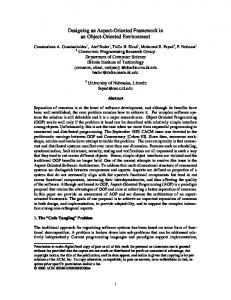
Fig. 1. TITAN running illustration.
original system. In this work, a simple scenario is used to present the problems that can be found and the solution proposed by TITAN. The scenario is about a customary vending machine system modelling how drinks are expended. When a costumer push a button the vending machine delivers the requested drink. A concern has been modelled as an aspect: It must be counted how many times an exhausted drink is requested. The system is now evolved with a new requirement: If one empty dispenser receives a request, this request must be addressed to another dispenser having the same product. The evolution will be faced using aspect-oriented techniques. That will only require the addition of a new aspect specifying the new requirement. This new aspect must be applied at the same joint point in which the first aspect is already operating, that is the points in which a drink is requested. The new aspect must operate before the previous one to avoid the first aspect count requests that can be fulfilled. However, due to the obliviousness principle, when the developer is going to perform this task, he is only aware of the functionality in which the aspect will be applied. In particular, he does not know how many aspects are affecting the same functionality. So, the new aspect will probably be woven incorrectly. That problem can be even more serious if the developer introduces some changes in the existing code in such a way that the points addressed by the aspects change. In those cases the malfunction of the original system will be caused. An additional problem appears when using programming languages such as Java, which protect the access to source code. Java uses bytecode format, protecting in this way the source code of classes. This originates the developer to lack precise information about the underlying system in which aspects must be applied. Then, the results of using languages such as AspectJ [7] to evolve systems can be even unpredictable. To sum up, the problems that can be found when evolving software systems using aspect oriented techniques are the following [8,9]: 1.
Unintended aspects effects. When pointcuts of new aspects are applied, they may be applied to undesired joint points of classes of the underlying system, and this could provoke unintended side effects.
2.
3. 4. 5. 6.
Arbitrary aspect precedence. When pointcuts of new aspects are applied, they may be applied to the same joint point as other (unknown) aspects already are. This may cause problems with the sequence of application of aspects Unknown aspect assumptions. When pointcuts of new aspects are applied, they may not find joint points matching existing requirements. Partial weaving. When the code of a system is modified, the aspects inside it may not be applied to future modifications. Incorrect changes in control dependencies. The advice type “around” can alter the behavioural semantics of a system. Failure to preserve state invariant. When an aspect is applied could break state invariants of the system.
In order to avoid these problems, it is necessary to perform verification operations that compare expected properties of the system (described during the modelling step) to the properties of the woven code. TITAN is a modelling framework providing support for that kind of tasks. Moreover, it is suitable for modelling large software systems because the built models can be easily scaled. III. TITAN FRAMEWORK The origin of the problem shown in the previous section is that when the system is evolved one cannot guarantee that the obtained behaviour is the expected one. To avoid that problem it is necessary both, to have a description of which the expected behaviour is and to be able to compare the obtained behaviour with the expected one. TITAN works in that direction (figure 1). In figure 1, ellipses represent UML specifications, stars represent testable representations of the models and edge labels represents actions performed in the TITAN framework. Using TITAN begins with the modelling of the required behaviour after the evolution using UML (1). For aspect modelling, TITAN uses Interaction Patterns Specifications (IPS) to describe the behaviour of the aspects. Aspects are instantiated in the original UML specification (2). The next step is the validation of the UML specification. For that, algebraic descriptions of the system are generated (3), and
used to perform model checking (4). Then, the validated model is used to generate extended state machines (5) in order to verify, simulate and test that the modelled behaviour is just the one expected by the designer. Finally, that model is compared (7) with that produced by the extended code obtained adding aspects (6). The aim of that comparison is to detect mismatches. In that way it is checked if the evolved system produces the expected behaviour. The next subsections describe the steps proposed by TITAN in more detail.
participant can reach. Second, to establish the current state of a participant when one aspect is going to be applied. Finally, to serve as a link among several specifications from different diagrams.
A. Generating the UML Specification The first step is to have a reference specification of the original system. Currently, UML is the most extended modelling language when systems are object oriented. In fact, it is an excellent tool to specify the behaviour of a system. But when aspects must be considered, the modelling process is more complex. Several authors have proposed solutions to that problem [2,3,4]. In particular TITAN extends UML specifications using the IPS approach [5,6] for modelling aspect behaviour.
Finally, the problem of the explosion of the number of states is mitigated by means of modelling states and interactions together and by grouping participants to reduce the number of describable situations.
In our proposal, IPS’s are used to describe the interrelations between the aspects and the system. IPS’s describe interaction patterns by means of sequence diagrams. A sequence diagram is a graphical depiction easy to use and easy to understand. In such IPS, each participant represents a different role. A role is a UML metaclass that must be later instantiated by a UML element. That element must satisfy the partial order of the messages defined in the role life line as well as other possible specified requirements. In order to build the expected behaviour system model, TITAN focuses on the interactions flow described in the sequence diagrams. Nevertheless, sequence diagrams have some limitations to be used as a modelling tool. The first limitation is that they offer only a partial view of the system. The second is that the description of interactions among participants is modelled at the level of instances whilst states machines only model interactions among component types. Finally, the description of every interaction can provoke an explosion in the number of states. TITAN takes these limitations into account. Next, how TITAN faces these problems is pointed out. A scenario provides a partial view of the system that must be contextualised with the rest of the scenarios in order to study the particular evolution of each participant. Different sequence diagrams are related by using UML invariant labels. These labels describe the state of components inside the scenario. States represented with labels can be defined by means of OCL equations, variable vectors or simply with state names. The labels are later used to check whether a pattern is applicable inside the scenario, as well as to build algebraic specifications and state machines. In order to achieve this, the life line (projection of the interactions of a participant inside a diagram) of each participant must start and end with a special label showing the state in which it starts and ends inside the described scenario. Therefore, labels have three different aims. First, to describe the evolution of the different states a
Scenarios can describe interactions among occurrences from different kind of participants whilst state machines are obtained for each participant type, this makes it necessary to organize the information into groups according to types, and detaching individual occurrences.
B. Instantiating patterns Patterns are instantiated by being integrated in the UML specification of the system. For that, once the aspects have been modelled it is needed to find points in the sequence diagrams of the model matching the requirements stated by aspects. These are the join points where aspects will be applied [6,10]. Notice that depending on the description of the aspects, different operations must be performed in order to instantiate the patterns. Further information about design and instantiation of IPS can be found in [11]. For each aspect to be integrated each message and role defined in an IPS, must be linked with messages and participants defined in the system specifications. This task requires some metainformation to describe the join point where the aspect must be applied and the way in that it must be composed. TITAN describes this metainformation using Component Aspect Assembly Descriptor (CAAD) [12]. CAAD is an XML descriptor to specify components and aspects interactions. These descriptions are used in order to join together aspect behaviour and sequence diagrams. Thus, the system can be easily increased by means of integrating new aspects, which are included in the model specifications. C. Validating specifications Next the obtained specifications are validated to detect errors and gaps. To do that, the first step is to compare the sequence diagrams with other UML diagrams, such as state diagrams and class diagrams. This kind of study can be usually performed by UML modelling tools. The errors detected can be either in the specification of the states represented with labels, or in the messages described. Nevertheless, interoperability problems as deadlocks or inconsistencies have not been detected yet. To cover this lack TITAN obtains “Calculus of Communicating Systems” (CCS) algebraic descriptions from sequence diagrams. The aim is to perform model checking. So, these algebraic descriptions are imported from the tool “Concurrency Workbench of the New Century” (CWB) [13]. Performing model checking with algebraic descriptions, allows the detection of gaps, deadlocks and forbidden event sequences in specifications [14]. The detected lacks must be fulfilled
extending the specification with new scenarios. Such scenarios can be positive as well as negative ones. A negative scenario is a forbidden sequence of events. The objective is to manage an errors free significant enough model of the system. A similar approach would be using state machines for that purpose. However, performing validation with model checking using process algebras is easier, because they provide a better support when using negatives and positives scenarios. Anyway, as it will be shown, TITAN proposes using state machines to simulate the system behaviour because it provides more precise information than algebraic descriptions. D. Obtaining state machines Once specifications have been validated, extended state machines can be automatically obtained for each element of the system. There exist several algorithms to perform this task [15]. TITAN uses the algorithm proposed in [16]. This algorithm is based on selecting the life lines of every scenario in which each participant is involved and it is also based on using state labels as links among them. The extended state machines obtained provide more precise descriptions than classical statecharts. In particular, they provide the possibility of representing time requirements and complex operations over groups of events (as critical regions) described with UML fragments. This provides support to perform an accurate simulation and model checking of the system model. The resulting extended state machines are cyclic labelled and directed graphs. Each vertex of a machine consists of a structure: where par, ord and crit are used for representing parallelism, sequences and critical regions; st is a string variable used for describing the current state of the component, and variables is used for describing the variables used in the conditions and iterations represented in the graph. As regards the edges, their main objective is to represent the protocol of events produced during the execution of one participant. To give sense to the sequence, it is necessary to include some information in the edges. This information represents each action described in the UML sequence diagram. Therefore, each edge consists of three parts: condition, event and action: •
“condition” is a logic expression returning true or false. If condition is evaluated to false, then neither the event nor the possible action is performed. • “event” consists of a structure where t describes the type of event (deliver “!” or reception “?”) and n is the name of the message (n ∈ N, where N is the finite set of system messages). • “action” is needed when using loops or clocks in sequence diagrams. Actions can contain initialisation operations or simple arithmetic operations. Counter variables or clock variables are positive integer values. A more detailed description of the extended state machines used in the TITAN framework can be found in [17].
E.
Simulation, verification and testing At this point the behavioural model of the expected system has been completed. The next step is to simulate, verify and test it to ensure that it is also correct, i.e. it behaves as expected. For this task TITAN uses UPPAAL [18]. UPPAAL is an integrated tool environment for modelling, simulating and verifying systems. It is appropriate for distributed systems that can be modelled as a collection of processes with finite control structure and real-valued clocks, communicating through channels or shared variables. The UPPAAL simulator enables to examine possible dynamic executions of a system during modelling stage and, thus, provides an inexpensive means to detect errors prior to the verification by the modelchecker. The UPPAAL model-checker covers the exhaustive dynamic behaviour of the system; it can also check invariant and reachability properties by exploring the state-space. All these characteristics allow us to study how the integration of new aspects affects the model built and its properties. F.
Comparing the expected and the obtained behaviours As a result of the previous steps, a correct model of the expected behaviour has been obtained. Meanwhile the code of the original system extended with the aspect has been generated. Now is time to check if the resulting system behaves as expected. For that, both model and code must be compared. That comparison does not require complete model specification but partial (significant enough) ones. The comparison is based on assuring that the properties of the model are matched by the code, and vice-versa. Model checking techniques are used to study the properties of both systems. Such study must be completed by means of simulating the same execution traces in both systems. In order to execute model-checking operations inside the obtained Java code, Java Pathfinder [19] is used. Hence, there are two steps to be done in order to compare machines and code simulation: 1. Generating tests from UPPAAL. These traces simulate the execution of state machines and can be used as inputs in the generated code. To know whether the code produce the same sequence of events that state machines, a tracing aspect can be applied to the Java code. 2. The same tracing aspect can be used to obtain the event sequence produced by the execution of the Java code. Such sequences can be simulated over the model with UPPAAL. Nevertheless, execution traces obtained may be too large due to the size of the systems built. In order to reduce its size, it is recommended to group state machines to facilitate the simulation and to focus the study on the interesting points. State machine grouping [20,21] allows obtaining descriptions suited to sets of components, abstracting their internal interactions. These groups will be adapted to the developer needs and will allow to create traces exclusively containing the events of interest. Later, the tracing aspect can be designed to only monitor the events of a set of state machines, avoiding references to events that occur inside grouped machines. Also, grouping machines softens the problem of state number explosion during model checking.
IV.
USING TITAN.
In this section, the vending machine example introduced in section 2 is used to illustrate the functioning of TITAN. As mentioned in section 3.A, TITAN assumes that we have a reference UML specification of the system to be evolved, and we will focus on the sequence diagrams. The scenario of this example describes how a sale is performed when the vending machine receives a request for a drink (figure 2). The sale takes places if there are available units of the requested drink. Otherwise, a message indicating that the product is exhausted. As we have said in Section 3, the first step using TITAN is the specification by means of IPS of the aspect to be integrated in the system. In the example the aspect is in charge of counting how often a drink is requested and it is exhausted. IPS makes reference to role names and abstract methods (marked with a preceding vertical bar in the diagram).
This information is expressed in XML format using CAAD [12]. Figure 4 shows how the aspect represented in figure 3 is integrated into the system. replier execution replier.available(*) { if ( replier.available?($1)≠ TRUE) {c.count_petititon()}}
Fig. 4 Aspect description using CAAD. st1
st2
st3
st4
st2
st3
st4
Fig. 2 Scenario for describing a sale. Figure 3 shows the IPS designed for describing the sequence of events that takes place when the product is not available. This IPS refers to two role names (“requester”, and “replier”), and two events (“available?(x)”, and “not_available(x)”) which must be instantiated, linking the aspect with the rest of the system.
In order to reduce the size of the specification, the additional information specifying how to link the IPS to the join point is not included in figure 4. Nevertheless, it is necessary to link the IPS role “|requester:|” to the “i:interface” element of the figure 2 and the “|replier:|:” role to the “s:storage” element. In addition, it is necessary to link the “|available?()” event to “check_drink ()”, “|not_available(x)” to “drink(ok?)”. Figure 6 (next page) represents the final scenario obtained once the aspect – figure 3 - has been integrated inside the sequence diagram of figure 2. st1 = drink_petition!( t.ok_petition? + t.not_petition? ) st2 = drink_petition? check_drink! drink?( t.charge_drink! ok_charge? deliver_drink! ok_petition! + t.not_petition!).st2 st3 = check_drink? drink! ( t.deliver_drink? st3 + t.count_petition! st3 ) st4 = charge_drink? ok_charge! st4 asp = count_petition?.asp … system = st1 | st2 | st3 | st4 | asp
Fig. 5 Algebraic descriptions in CCS obtained from Fig. 6
Fig. 3 IPS description from the example
The following task using TITAN is validating the UML specifications so obtained. TITAN allows to generate algebraic descriptions in CCS from sequence diagrams. A state label for each element must be used as initial state. From this point onwards, the rest of labels are used to link information. Performing model checking with algebraic descriptions, allows the detection of gaps, deadlocks and forbidden event sequences in specifications [14]. To cover these lacks new requirements must be added to the initial UML specifications. For instance, forbidden event sequences can be described in UML using “negative” fragments. This characteristic allows to validate the system in a more precise way than state machine simulations do. Each error detected
st1
st2
st3
st4
asp
IPS st1
st2
st3
st4
asp
Fig. 6 Final scenario when aspect is integrated implies returning to the UML model in order to complete the specification and iterate the whole process again. Figure 5 shows the CCS specifications of the scenario described in figure 2, where m! represents the delivering of a message m and m? represents the corresponding reception; the operator “.” indicates sequence, and “+” indicates alternative behaviour. Finally, “t” represents an internal action, that yields to an internal choice when combined with “+” as in the example in figure 5. In the vending machine example, performing model checking with the specifications from figure 2, allows to detect a deadlock in the system. The cause is that a state label was omitted. Such situation is produced once the “cu:customer” element requests a drink. When the request is attended, “cu:customer” evolve from the initial state (“st1”) toward an unspecified state. To solve this problem, it is necessary to integrate one state label in “cu:customer” in order to describe the final state and to be able to return to this state when execution is finished. Once the deadlock has been eliminated the next step is obtaining state machines for the system. In the state machines proposed by TITAN the vertexes contain a data structure representing information about the UML fragments and the values of system variables. As regards state machine edges, event sequences can be represented as well as conditions over the variables, and updating and initializations of them. Figure 7 shows the machines obtained from the example.
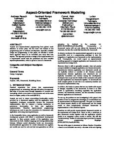
These state machines model the expected behaviour of the system. Now, it is possible to proceed with the simulation, verification and testing of the properties of the new system. Such properties can be compared with those of the original system (before the new aspects are integrated) and thus they facilitate the study of its evolution. TITAN simulates the machines with UPPAAL. Following all the steps above, a correct specification of the expected behaviour has been obtained. Then, the code of the original system extended with the aspect can be generated, and the behaviour of the model and that of the system extended with the new aspect can be compared. TITAN uses Java Pathfinder to analyze the Java code of the evolved system. The analysis consists on checking that the test traces obtained from the state machines (figure 7) are accepted by the Java code and vice versa. To know whether the code produce the same sequence of events that state machines a tracing aspect is generated and applied to the Java code. A trace represents an accepted events sequence by the model. Each event in the sequence is a method invocation. The tracing aspect supervises the system execution detecting all invocations, and checking whether that sequence is the same produced by UPPAAL. Besides, this tracing aspect generates traces in UPPAAL format so they can be tested by the simulator.
Simulation traces
Fig. 7 Extended state machines of the model and one trace of simulation
Sometimes, these test traces can be too large. With the aim of reducing their size, TITAN allows for grouping components. In order to achieve this, state machines whose individual behaviours are not interesting can be grouped, abstracting references to events that occur inside grouped components. The tracing aspect can be designed in such a way that it only monitors the events of a series of selected classes. Returning to the example, figure 8 represents the grouping of the state machines “interface” and “purse” in figure 7. The resulting grouped machine is smaller than the previous ones because it does not depict events that are internal to them. This allows us to focus the study on the classes affected by the pointcuts of the aspects of the system. These groupings allow us to reduce the size of the system model as well.
Figure 8. Grouping state machines
Now, it is possible to deal with new evolutions of the system performing again all the steps above. In section 2 it was discussed a second property extending the vending machine system: to introduce the possibility of having duplicate dispensers delivering the most popular drinks. When one of these dispensers is empty, it will send the received request to another dispenser with the same product. The new aspect must be applied at the same point where the previous one was integrated. In order to avoid duplicate counting of already fulfilled request the new aspect must operate before the previous one. With the intention of reducing the size of this paper, the specification of this aspect is not included. However, the system is easily augmented by integrating the new aspect inside the built model. With respect to this integration, new IPS will be linked to the sequence diagram of the system just before the IPS corresponding to the first aspect. The final model obtained once the state machines have been automatically generated. Depending of the aspect oriented programming language used the new aspect will be woven before or after the existing one. If it is done after it will result in incorrect behaviour. Anyway, the comparison step with TITAN will reveal it. Furthermore, if the aspects were woven incorrectly, the analysis of the traces will reveal the exact cause of the problem and the point in which it appears. The analysis can be completed through model checking operations which allow us to detect pathologies in the properties of the obtained system. V.
RELATED WORKS
When a system is extended with different aspects, there are two main effects. On one hand, the original system has new properties. On the other, the original purpose of the system
may have changed. But there is no tool that allows to study in depth the relationships among the system and the aspects added to it. Several research works study some practical aspects of this integration by means of restricting some characteristics. There are works that analyse the properties of the completed system, with the new aspects integrated, either by using model checking [22] or static analysis of the code [23]. Other works study how the inclusion of one aspect affects the properties of a specific woven system [24], or every possible way of weaving the aspect inside the code [25]. Some works analyse how the inclusion of aspects affects a system by means of comparing the properties after and before their integration [26], others develop a fault model for aspect-oriented programming, including the different types of faults that may occur [9]. As regards testing works, a framework to generate tests for AspectJ programs using wrapper is proposed in Xie [27]; Zhao proposes a data-flow-based unit testing approach for aspect-oriented programs. Zhou has introduced an algorithm based on control flow analysis to select relevant test cases for aspect-oriented programs [28]. Nevertheless, all these works are based on testing the behaviour of built systems. Our approach is different from previous works because TITAN creates a model of the system. Model-based testing improves the detection of errors and decreases testing costs. This feature is possible because testing process can be semi-automated. The number of test cases can be increased, decreasing in this way the number of errors [29]. The model built can also be compared to the final system, thus helping to verify the implementation obtained. Other sort of related works are those supporting system modelling and verification. Motorola Weavr is an add-in for Aspect-Oriented Modelling in Telelogic Tau G2 [30]. This add-in provides support for the system modelling, verification but it is focused on code generation. Weavr uses a different jointpoint model since pointcuts are not based on the implementation, but they are related to the history of the events of the system. Besides, Weavr describes aspects behaviour using statecharts instead of extended states machines. Xu et at. [31] also use a model of the system to test integration aspects. They use UML statecharts to capture the expected interaction between base classes and integrated classes. However, TITAN builds the model starting from valid specifications, obtained with sequence diagrams. The extended state machines built are more precise than statecharts. Thus, TITAN allows us to perform better analysis from the system. Moreover, performing machines grouping allow us to adapt the model to each evolution. VI.
CONCLUSIONS
AOP facilitates the evolution of a software system. However, adding new aspects to an existing AO system could produce an unexpected behaviour. TITAN introduces a practical approximation that evolves the requirements of the system, described by means of sequence diagrams in UML. These UML specifications, once validated, will allow us to
obtain a system model (extended state machines) which behaviour could be automatically tested. Model-based testing improves the detection of errors and decreases testing costs. Moreover, in order to facilitate these operations, grouping state machines has been proposed to reduce the size of the tests and to focus the study on the involved classes. These features allow us to easily scale the system making this framework suitable for modelling large software systems. With system modelling, it is possible to simulate how a software system will be affected when different aspects are included. It is also possible to perform model checking of the properties of the model and the results can be compared with those belonging to the woven code. Besides, we can study the resulting woven code when an aspect is included, by means of trace simulation between system model and the built code. Using TITAN, the comparison between the new expected behaviour modelled and the final woven code, detects all problem related in section 2, excepting the failure to preserve the state invariant. But this problem can be detected with TITAN making model checking operations. As regards the limitations of our proposal, TITAN needs to validate specifications manually in order to build a correct model. Anyway, this limitation only happens when the system is being developed by the first time. Subsequent evolutions require more simple validations. REFERENCES [1]
Fillman R., Friedman D. “Aspect Oriented Programming is Quantification and Obliviousness”. In Aspect- Oriented Software Development (edited by Filman, R.E. et al.). Addison-Wesley, 2005. [2] Elrad, T., Aldawud, O., and Bader, A. “Expressing aspects using UML behavior and structural diagrams”. In Aspect- Oriented Software Development (edited by Filman, R.E. et al.). Addison-Wesley, 2005. [3] T. Aldawud, and A. Bader, “UML profile for aspect-oriented software development”, Position paper for the Third International Workshop on Aspect Oriented Modeling, 2003. [4] D. Stein, S. Hanenberg, and R. Unland. “An UML-based aspect-oriented design notation for AspectJ”. In Proceedings of the 1st international conference on Aspect-oriented software development, pages 106–112. ACM Press, 2002. [5] R. B. France, D. Kim, S. Ghosh, E. Song. “A UML-Based Pattern Specification Technique”. IEEE Transaction on Software Engineering. March 2004 (Vol. 30, No. 3) pp. 193-206. [6] J. Araujo, J. Whittle, D. Kim, "Modeling and Composing ScenarioBased Requirements with Aspects", pp. 58-67, 12th IEEE International Requirements Engineering Conference (RE'04), 2004. [7] AspectJ. http://www.eclipse.org/aspectj [8] N. McEachen, R.T. Alexander. “Distributing classes with woven concerns: an exploration of potential fault scenarios”. 4th International Conference on Aspect-Oriented Software Development. Pag: 192 – 200, 2005. [9] R. T. Alexander, J. M. Bieman, and A.A. Andrews. “Towards the systematic testing of aspect-oriented Programs”, Technical Report, Colorado State University. http://www.cs.colostate.edu/~rta/publications/CS-04-105.pdf. [10] Aldawud, O., Bader, F., and Elrad, T. “Weaving with Statecharts”. The Second International Workshop on Aspect Oriented Modeling. 2002. [11] J. Whittle, J. Araujo. “Scenario Modeling with Aspects”. IEE Proceedings - Software -- August 2004 -- Volume 151, Issue 4, p. 157171.
[12] Clemente, P.J.; Hernández, J. Sánchez, F. “Driving component composition from early stages using aspect-oriented techniques”. In International Conference on System Services (HICSS07) proceedings. Hawaii January 2007. [13] Concurrency Workbench of the New Century (CWB-NC). http://www.cs.sunysb.edu/~cwb [14] S. Uchitel. “Incremental elaboration of scenario-based specifications and behaviour models using implied scenarios”. ACM T.O.S.E.M. Volume 13, Issue 1 (January 2004), Pages: 37 – 85, Year: 2004, ISSN:1049331X. [15] International Workshop on Scenarios and State Machines: Models, Algorithms and Tools, Saint-Louis (EEUU), May 2005. [16] J. Whittle, J. Schumann. “Generating Statechart Designs from Scenarios”. 22nd International Conference on Software Engineering. Pag. 314 – 323, 2000. [17] M. A. Pérez Toledano, A. Navasa Martínez, J. M. Murillo Rodríguez, C. Canal. “Making Aspect-Oriented System Evolution Safer”. Proceedings of the Workshop on Reflection, AOP and Meta-Data for Software Evolution, ECOOP, Nantes (France), July 2006. [18] UPPAAL. http://uppaal.com [19] Java Pathfinder. http://javapathfinder.sourceforge.net [20] L. Blair, G. Blair. “Composition in Multi-paradigm Specification Techniques”. Third International Conference on Formal Methods for Open Object-Based Distributed Systems (FMOODS). Pag. 401 – 417, 1999. [21] M. A. Pérez Toledano, A. Navasa Martínez, J. M. Murillo Rodríguez. “Using Interaction Patterns for Making Adaptors among Software Components”. Proceedings of the Workshop on Coordination and Adaptation Techniques for Software Entities, ECOOP, Glasgow (United Kingdom), July 2005. [22] S. Katz, M. Sihman. “Aspect Validation Using Model Checking“. Symposium de Verification,Zohar Manna, LNCS 2772, pag 389-411, June 2003. [23] C. Clifton, G. Leavens. “Observers and Assistants: a Proposal for Modular Aspect-Oriented Reasoning”, Foundations of Aspect Languages (FOAL), 2002. [24] S. Krishnamurthi, K. Fisler, M. Greenberg. “Verifying Aspect Advice Modularly”, International Conference on Foundations of Software Engineering (FSE) , 2004. [25] B.Devereux. “Compositional Reasoning about Aspects Using Alternating-Time Logic”, Foundations of Aspect Languages (FOAL) 2003. [26] S. Katz. “Diagnosis of Harmful Aspects Using Aspect Languages” Foundations of Aspect Languages (FOAL) 2004. [27] T. Xie, J. Zhao, D. Marinov, D. Notkin. “A Framework and Tool Supports for Generating Test Inputs of AspectJ Programs”. In Proceeding AOSD'2006, Bonn (Germany), March 2006. [28] Zhou, Y., Richardson, D., and Ziv, H. “Towards a practical approach to test aspect-oriented software”. In Proc. Workshop on Testing Component-Based Systems (TECOS), Sept. 2004. [29] B. Beizer. “Software Testing Techniques”. International Thomson Computer Press, 1990. [30] Motorola Weavr. http://www.iit.edu/~concur/weavr [31] Xu, W and Xu, D. “State-based testing of integration aspects”. In Proceedings of the 2nd Workshop on Testing Aspect-Oriented Programs (WTAOP 2006), July 2006.