t
Anno 2010_Numero 169
apporti
tecnici
TLS point clouds texturing: the manual of Matching Viewer software
Istituto Nazionale di Geofisica e Vulcanologia
Direttore Enzo Boschi Editorial Board Raffaele Azzaro (CT) Sara Barsotti (PI) Mario Castellano (NA) Viviana Castelli (BO) Rosa Anna Corsaro (CT) Luigi Cucci (RM1) Mauro Di Vito (NA) Marcello Liotta (PA) Simona Masina (BO) Mario Mattia (CT) Nicola Pagliuca (RM1) Umberto Sciacca (RM1) Salvatore Stramondo (CNT) Andrea Tertulliani - Editor in Chief (RM1) Aldo Winkler (RM2) Gaetano Zonno (MI) Segreteria di Redazione Francesca Di Stefano - coordinatore Tel. +39 06 51860068 Fax +39 06 36915617 Rossella Celi Tel. +39 06 51860055 Fax +39 06 36915617
[email protected]
t
t
apporti
tecnici
TLS POINT CLOUDS TEXTURING: THE MANUAL OF MATCHING VIEWER SOFTWARE Arianna Pesci1, Elena Bonali2, Giordano Teza3, Giuseppe Casula1 1INGV (Istituto Nazionale di Geofisica e Vulcanologia, Sezione di Bologna) 2UNIVERSITÀ 3UNIVERSITÀ
DI BOLOGNA (Dipartimento di Architettura Pianificazione Territoriale) DI PADOVA (Dipartimento di Geoscienze)
Anno 2010_Numero 169
Table of contents Introduction 1. Standard procedure for ILRIS data parsing and texturing 2. Procedure for ILRIS point cloud texturing with external mounted camera 2.1. Parsing part 2.2. Match Viewer part Aknowledgments References
5 7 9 9 10 12 13
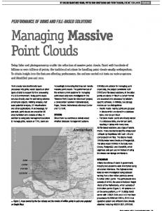
Introduction A time-of-flight terrestrial laser scanner (TLS) works like a laser rangefinder but is also able to scan a surface with a selected sampling step, leading to a point cloud defined into an internal reference frame. Moreover, radiometric information about signal returns intensity is provided, computed in terms of the ratio between emitted and received pulse intensities. Besides the geometric and radiometric data, some TLS instruments, equipped by an internal or an external calibrated camera, are able to provide also the RGB information by mean of a texturing procedure, i.e. a procedure of point cloud coloring. In general, the mapping of a 2D RGB image onto a digital surface model during 3D rendering, increases the realism of the resulting model. The point cloud texturing is currently used in TLS observation aimed to cultural heritage study and preservation (see e.g. Beraldin et al., 2002). The texturing procedure consists in camera calibration and orientation. The camera calibration models the true parameters of the camera (i.e. focal length, format size, principal point, and lens distortion, see e.g. Tsai 1986, 1987), whereas the orientation process leads to the position and angles of the camera with respect to the point cloud reference frame. Pairs of corresponding points, visible both in the captured RGB image and in the corresponding point cloud can be selected and used to solve for the calibration parameters of the camera in a the least square approach. Depending on the unknown quantities that must be obtained, in particular the availability of calibration parameters of the camera for the considered field, the procedure requires the detection of some or several pairs of corresponding points. In some cases, 13 parameters could be necessary, and at least 20 pair of points are therefore needed to have an adequate redundancy in the least square computation. The Optech ILRIS 3D (Optech, 2010) is a TLS instrument characterized by good performance in long range acquisition (up to 1200 m), which is equipped with an internal integrated camera (3 megapixel) to provide the RGB information and therefore allow the point cloud texturing. The format of the data directly provided by a TLS instrument is specific for the instrument. In order to allow their importation by the standard data processing software packages (e.g. Innovmetric PolyWorks, I-Site Studio, Leica Cyclone. For a list of available packages see e.g. GIM, 2009), a parsing procedure is necessary. In the case of ILRIS instrument, the parsing procedure is implemented in Optech Parser software and is well described also in the short manual provided by Pesci et al. (2009), where significant information about the planning and the definition of a reasonable acquisition protocol of a TLS measurement is also provided. A new feature available in Optech Parser allows the point cloud texturing, by means of 2D images captured at the scanning epoch by the internal camera by using the camera calibration certificate of the integrated camera. In particular, to perform the computations, the "texture image" and the “texture calibration parameter” files have to be used. The first file is the image automatically stored by the scanner and the second one is provided by Optech (Optech, inc). If these two files are directly used, the texturing procedure is completely automatic. Nevertheless, in some cases a high accuracy in RGB data treatment is necessary, and the recognition of an adequate number of pairs of corresponding point must be carried out by means of Optech Matching Viewer software package (Optech, inc). The Matching Viewer package is able to provide a texture calibration parameter file for a fine texturing. This technical report describes in detail the procedure for point cloud texturing using images from an external calibrated digital camera and Matching Viewer. In particular, the Nikon reflex D50, which is characterized by 28-mm focal length and 8.0 megapixel resolution. A TLS survey of the Santo Stefano historical square of Bologna city, aimed to provide the high resolution acquisition of Corte Isolani Palace, is performed. Figure 1 shows the external camera mounted on the ILRIS instrument during the survey. The scanner handle is shaped to allow the high precision installation of a camera on a calibrated position. Anyway the mechanical components lead to alignment errors to be corrected by means of a specific matching procedure described in the following.
5
Figure 1. The ILRIS 3D (ER) working in the Santo Stefano square; the external camera (Nikon) is mounted on the scanner handle. The image in the display is the one captured by the internal camera.
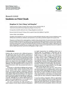
Figure 2. Images captured by the external and internal cameras. The first image, provided by with an external camera (upper panel), is more detailed and shows clean color tones. On the contrary, several details (for example the fissure) are not well visible but blurred in the other imaged, provided by the internal camera (bottom panel), due to a lower resolution and worse quality of optical components. 6
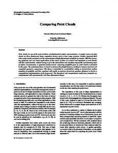
1. Standard procedure for ILRIS data parsing and texturing As stated, the data parsing converts the metafiles of survey scans (in i3d format), containing the binary files of data, the information about scan setting, the operator notes and the image of survey scene, into a format that can be managed by the standard data processing packages. The Optech Parser provides the default files suitable for importation of Optech data in PolyWorks (Innovmetric, 2010), or also in format compatible with standard GIS or modeling software. It is designed to make it quick and easy to parse and re-parse data again and again, trying out new settings each time. On the other hand, the Parser’s main features are the ability to provide several output formats in terms of both range and intensity gate and to operate data reduction to resize the data density and overall file size. The parsing procedure is carried out in the following steps: (i) once the scan folder (containing files in .i3d format) data is copied in the local PC, Parser.exe is executed and, using the Add button, the folder where the available files are stored is chosen (alternatively, the command Click File > Load > Scan Project can be given); (ii) the image of survey scene are compared in the left space of the window together with the ROI (Range of Interest); (iii) to create the intensity point cloud, the Settings button is pushed (or a command from the menu Settings > Parsing Settings is given); (iv) the output folder is created and the Output Format is chosen from the list. If the TLS data are related to a point cloud acquired with a single scan or few scans, the recommended output format is PIF, with 8-bit scaled intensity (0-255 grey levels intensity is provided besides the coordinates for each point in which parsing can be successfully carried out). If the point clouds are related to an extended object that surrounds the TLS viewpoint (angular extension larger than 100°), the IXF format is instead recommended, since it allows a better compensation of the alignment and modeling errors (PIF format is related to a planar grid, IXF to a spherical grid). Moreover, the IXF format is also recommended if Matching Viewer package is used. Finally, (v) the parsed data are stored in the PIF (or IXF) folder. If an RGB image of the scene is available, the point of view is almost the same and if the calibration parameters of camera are known, which is the case of the internal camera of a TLS instrument, or also the case where the calibration of the external camera is carried out with a suitable software package, the point cloud texturing can be carried out. The parsing procedure is now carried out in the following steps: (i) choose of the PIF format and selection of the 24-bit texture (RGB) option; (ii) from the Parser Settings window, selection of the Color Channel in the left panel, or selection of Settings > Color Channel from the main screen. The Color Channels options appears; (iii) choose of the folder where the jpeg image is store (if the image acquired by the internal camera is used, it is generally saved in the scan folder together with scan data) in the area Texture image file (OptecTM ILRIS-3D Operation Manual, 2006). (iv) choose of the calibration camera parameters file in the area Texture Calibration Parameter file and parsing. (v) The procedure is briefly illustrated in figure 3, where the main parameter selected for both the intensity and textured point clouds are shown.
7
Figure 3. The main panels of parser.exe tool for the creation of standard PIF files, colored with the intensity grey scale (8-bit) and with the RGB from internal camera image (24-bit).
8
It is to underlie that Optech Parser supports the following output formats: (1) PIF, PolyWorks binary format; (2) XYZ, Standard ASCII text file with X, Y, Z and I (intensity) in a righthand coordinate system, in meters; (3) Raw, ASCII text file of raw scanner encoder counts for azimuth angle (theta), elevation angle (phi), slant range and intensity data (x 100); (4) PTX, Leica exchange format; (5) 3DV, XYZ input file with shot ordering (row, column) specified, saved in PIF coordinate system; (6) BWP, BitWyse format; (7) S3D, SIAMS S3D format; (8) PTC, ASCII point cloud format that is similar to XYZ format; (9) BLF, BitWyse laser format; (10) IVA, Same as PTX format, except that XYZ and intensity data are saved in .3lf format; (11) IXF, i.e. ILRIS Exchange Format optimized for spherical grid representation. As above stated, the latter format (IXF) is important because it is used in the point cloud texturing by using image from an external digital camera.
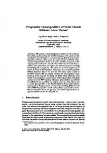
2. Procedure for ILRIS point cloud texturing with external mounted camera In this section the procedure for texturing an ILRIS point cloud using images captured by an external digital camera is described. It consists of two main steps: the generation of a specific IXF file parsing the acquired ILRIS metafile data and the application of the Matching Viewer software to match the images to the point cloud. Despite the fact that the external camera is high precisely installed on the available calibration points in the scanner handle, and the calibration parameter file is provided by Optech, matching operations are required to correct for mechanical alignment errors occurring in the mounting phase. On the other hand, the relative positions of the instrument and observed surface could lead to use of zones of the camera lens relatively far from the focal axis. 2.1. Parsing part The generation of the IXF file is a simple procedure that can be carried out in the following steps: (i) Start of the Parser.exe program and scan project opening (select File>Load>Scan Project); (ii) selection the output IXF format (Select Settings>Output File) and selection of 8-bit scaled IXF intensity; (iii) in the Parsing Setting list, selection of Shot Alignment & Reduction and verification that the Trim Shots box is checked; (iv) in the Parsing Setting list, selection of Miscellaneous and verification that the check box is disabled; (v) in the Parsing Setting list selection of Pantilt Transform and verification that the Apply Pan-tilt Transform check box is disabled; (vi) Selection of Ok and Parse.
Figure 4. The procedure to create the IXF file (8-bit scaled). 9
2.2. Match Viewer part The image texturing is operated using the Match Viewer software and following the next steps: (i) opening the Matching Viewer program; (ii) selection of Function menu and choose of BoresisghtOrientation; (iii) selection of Reference (point cloud) and import the IXF file; (iv) selection of Data (RGB image) and browsing of the folder where images are saved and, finally, selection of the jpg image. In this way, the calibration parameters can be estimated by comparing Reference and Data with the technique of epipolar geometry. Once they are loaded and displayed, the Selecting Common Feature procedure can start: (v) the simple mouse controls are used to adjust the zoom factor of the image and of the point cloud; (vi) the first pair points is selected with the left mouse button and the right button is used to confirm the choice; (vii) when the firs point pair is selected and the Camera Calibration file Selection Window appears, the file with the internal camera parameters can be choose; (viii) the point pairs selection is continued until at least 5 point pairs are obtained. To have a good result, the points pairs should be well distributed all around the scene both in the point cloud an in image. Moreover, since a least square approach is used, the result improves if the number of selected point increases. Other information about the required number of chosen pair is provided below.
Figure 5. The main interesting panels of the Match Viewer, described in the main text. a, b, c) Point cloud and image import; d) first homologous point pair selection; e) importing of the calibration camera file; f) complete selection of corresponding point pairs. The calculation of the Boresight Angle is the next step of the procedure. In particular: (ix) in the lowerleft corner of the Matching Viewer main window, the item Calculate must be selected; (x) the calibration occurs and when it is complete, the Camera Cal window appears, showing an RMS value. If this RMS value 10
is lower that 2 the calibration is good. If the RMS is in the range 2-8 the calibration is acceptable. Finally, if the RMS is larger than 8 the procedure must be repeated, selecting other common point pairs. The Matching Viewer package generates a *.ccp, *.err and a *.txt file. The .txt file is the most important file because it contains the boresight angles, camera position, and camera distortion corrections. This file will enable the parser to drape the photo onto the scan. Finally, to texture the point cloud using the image captured with the Nikon D50 camera, the standard parsing procedure is repeated as described in previous section, applying the Camera Calibration just computed.
Figure 6. The main interest panels of the Match Viewer, described in the main text. g) the calculation of boresigth orientation; h, i) saving and exporting results; j) the text files for computed calibration parameters (txt), homologous point pairs positions (ccp) and points differences (err).
11
Figure 7. The textured point clouds with internal and external cameras.
Acknowledgments Thank you very much to Marco Bacciocchi and Andrea Faccioli for the concession of the Nikon external camera and of the software.
12
References Androni D.C., Pinto L., 2006. Il Texture mapping del Battistero di Cremona ottenuto con riprese fotogrammetriche digitali e laser scanner terrestre, ASITA X Nat. Conf., Bolzano, Italy. Beraldin, J.-A., Picard, M., El-Hakim, S.F., Godin, G., Valzano, V., Bandiera, A., Latouche, D. (2002). Virtualizing a Byzantine Crypt by Combining Highresolution Textures with Laser Scanner 3D Data. in Proceedings of VSMM 2002, Gyeongju, Korea. September 25-27, 2002, pp. 3-14. Bornaz L., Lingua A., Rinaudo F. (2002) “Calibrazione di immagini non metriche mediante l’uso dei dati laser scanner terrestri”. Atti della 6a Conferenza Nazionale ASITA “Geomatica per l'ambiente, il territorio e il patrimonio culturale”, vol. I, Perugia, pp.. 493 – 498. GIM (2009) GIM International terrestrial laser scanner product survey. Available online at: http://www.giminternational.com/files/productsurvey_v_pdfdocument_33.pdf (accessed: 22.06.2010). Innovmetric, 2010. Innovmetric PolyWorks software description. http://www.innovmetric.com/polyworks/3D-scanners/home.aspx (accessed: 10.06.2010). OPTECTM ILRIS-3D Operation Manual (2006). Optech Incorporated Industrial & 3D Imaging Division, 0040170/Rev A, 1-147. Optech, 2010. ILRIS 3D laser scanner description. Available online at: http://www.optech.ca/prodilris.htm (accessed: 10.10.2010). Pesci, A., Loddo, F., Conforti, D. (2007). The first terrestrial laser scanner survey over Vesuvius: the high resolution model of volcano crater (Napoli, Italy). International Journal of Remote Sensing, 28, 1, 203219. Pesci A., Teza G., and Ventura G. (2008). Remote sensing of volcanic terrains by terrestrial laser scanner: preliminary reflectance and RGB implications for studying Vesuvius crater (Italy). Annals of Geophysics, Vol. 51, Num. 4, August 2008, pp. 633-653. Sabry El-Hakim, 2005. A practical approach to creating precise and detailed 3D models from single and multiple views. CIPA XX Int. Symp., Turin, Italy. Tsai, R.Y. (1986). An Efficient and Accurate Camera Calibration Technique for 3D Machine Vision. Proceedings of IEEE Conference on Computer Vision and Pattern Recognition, Miami Beach, FL, pp. 364-374 Tsai, R.Y. (1987). Metrology Using Off-the-Shelf TV Cameras and Lenses. IEEE Journal of Robotics and Automation, 3, 4, 323-344.
13
Coordinamento editoriale e impaginazione Centro Editoriale Nazionale | INGV Progetto grafico e redazionale Laboratorio Grafica e Immagini | INGV Roma © 2010 INGV Istituto Nazionale di Geofisica e Vulcanologia Via di Vigna Murata, 605 00143 Roma Tel. +39 06518601 Fax +39 065041181 http://www.ingv.it
Istituto Nazionale di Geofisica e Vulcanologia