Tolerance-Band Modulation Methods for Modular Multilevel Converters Arman Hassanpoor, Kalle Ilves, Staffan Norrga, Lennart Ängquist, Hans-Peter Nee ROYAL INSTITUTE OF TECHNOLOGY (KTH) Teknikringen 33, 10044 Stockholm, Sweden Tel.: +46 / (8) – 7906000 Fax: +46 / (8) – 75211793 E-Mail:
[email protected] URL: http://www.kth.se
Keywords HVDC, Voltage Source Converter (VSC), High voltage power converters, Switching losses
Abstract Modular multilevel converters (M2C) are increasingly used in high voltage direct current (HVDC) systems. The efficiency of M2Cs is highly related to the modulation method which determines the switching frequency and capacitor voltage ripple in the converter station. A new approach to modulation of M2C is presented in this paper. Tolerance-band methods are employed to obtain switching instants, and also cell selection. The proposed methods overcome the modulation problem for converters with few numbers of cells and also reduce the sorting efforts for cell balancing purposes while maintaining the cell-capacitor voltage limits. The evaluation is done by time-domain simulation by which the performance of each method is studied in both steady-state and transient cases. It is observed that using tolerance band methods not only reduces the switching frequency but also allows for handling severe fault cases in a grid connected system. Use of this method can reduce the switching losses and also allow for reduction of the cell capacitor size.
Introduction Modular multilevel converters (M2C) are becoming more widely used in power system applications, such as high voltage direct current (HVDC) transmission [1]-[3], flexible alternating current transmission systems (FACTS) and electric railway supply [4]-[5]. Compared with two- and threelevel converters, M2C has smoother output voltage and much lower power losses because of reduced switching frequency. However, it requires more a complex control system and more advanced modulation strategies. Several modulation methods have been presented based on carrier-based pulse width modulation [6], space vector modulation (SVM) [7] and nearest level control (NLC) [8] but current research continuously attempts to introduce more efficient methods to reduce the switching frequency. A modulation method should also balance the cell capacitor voltages. The capacitor voltages can be controlled either by employing a sorting method [7] or cell voltage feedback [6]. Both methods have advantages and disadvantages in different applications. Ranking hundreds of cell voltages during a small time-step is problematic, and feedback control may restrict the implementation of advanced modulation methods. This paper focuses on these contradictory requirements and proposes a novel method based on tolerance band control. This is an entirely new approach in M2C low-level control, by which not only the switching frequency is reduced, but also the sorting actions are only performed only few times in each fundamental cycle. Therefore, the control system requirements are reduced in comparison with conventional sorting methods. The paper is divided into four parts. A description of M2C is given in first part. The second part provides a detailed description of the proposed method for flux tolerance band control, and also cell selection algorithms. Simulation results are presented in the third part, and finally, conclusions are drawn in last part.
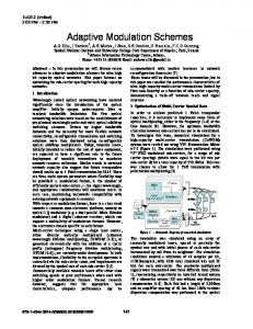
Description of M2C Topology The schematic of the three-phase M2C topology is shown in Fig. 1a. The converter is connected to the alternating current (AC) grid by a transformer in the point of common coupling (PCC). Each phase of the converter contains two arms and each arm has N number of series connected cells along with a phase inductor. As shown in Fig. 1a, each cell consists of a capacitor (C) and two semiconductor switches (Si1 and Si2). Controlling the turn-on/turn-off of the semiconductor switches shapes the AC and DC voltages in the desired way. When Si1 is in the on-state and Si2 is in off-state, the cell is inserted and the cell capacitor voltage, Vc(i), will vary depending on the arm current. On the other hand, when Si1 is in the off-state and Si2 is in the on-state, the cell is bypassed and the cell capacitor voltage remains constant. Hence, the generated AC voltage depends on the switching pattern. As discussed in [9], the cell capacitor voltage ripple, the semiconductor switching losses and the output voltage quality are contradictory aspects of M2C operation, which need to be controlled by proper modulation strategies.
Equivalent Circuit Each converter arm can create discrete voltage levels between zero and Vdc in steps of Vc(i). Since each arm includes tens or hundreds of levels, it can be assumed that each arm is corresponding to a variable voltage source. Accordingly, the equivalent circuit of one phase system is defined in Fig. 1b. The voltage Varm is the instantaneous value of the ac-side voltage imposed by the cells. The two parallelconnected inductors Larm indicate the arm inductors, which from the ac- side appear to be connected in parallel. LT is sum of the transformer leakage reactance and any other reactance between the converter and the grid. Resistive losses of the transformer and the grid side are also gathered in one resistance, RT, while Rarm is the converter arm resistance. Hence, the equivalent circuit consists of two voltage sources that are connected through an inductance Leq, and a resistance Req, which are given by =
=
1 2
+
+
Fig. 1: (a) Three-phase schematic of M2C, (b) Equivalent circuit
(1) (2)
Method Description An overview of the proposed methodology is shown in Fig. 2a. A desired reference voltage (vref) is generated by the converter high-level control. The low-level control then produces the firing pulse pattern for each individual cell. As proposed in [9], the modulation strategy can be decoupled from the cell selection. The modulation part continuously determines the number of inserted cells (Nlevel) and a cell selection method chooses the cells to insert/bypass to balance the cell capacitor voltages. In this section, novel methods, based on tolerance band control, are proposed for the modulation, as well as the cell selection parts.
Flux Tolerance Band Control The derivations in this section are based on the equivalent circuit in the previous part, Fig. 1b. The relation between the voltages and the current, is, is then given by −
=
+
(3)
= ∫(
−
−
)
(4)
) .
(5)
consequently,
that is, the voltage integral (flux) as given by = ∫(
−
−
We now define the is the differential flux as =
−
.
(6)
where, ψeq is the actual flux and ψreq is the requested flux. The controller should keep the flux within ±δ of its desired value, that is −