software development process, which corresponds to the model- driven software ... Software development companies are providing solutions to the client ...
Scientific Journal of Riga Technical University Computer Science. Applied Computer Systems
2010
________________________________________________________________________________________________
Volume 43
Tool Integration to Support SPEM Model Transformations in Eclipse Vladimirs Nikulsins, Riga Technical University, Oksana Nikiforova, Riga Technical University Abstract - This paper propose the approach for integrating SPEM modeling tools with the Query/View/Transformation (QVT) tools using Eclipse Modeling Framework (EMF). The aim of tool integration is to support the adoption of Model Driven Architecture within the organizations, which currently use “traditional” software development approaches. The software development process lifecycle of organization is supposed to be expressed with the help of OMG SPEM language. The approach presented in the paper is based on the model-level integration using EMF based interfaces, which will help to link the MOF based Ecore models with the QVT transformation tools. The outcomes of the work are: (i) the design of EMF based tool integration, (ii) solution prototype for Eclipse environment (iii) QVT Relations transformation rules. Model transformations are performed using mediniQVT tool, which is able to operate with the models expressed as Ecore metamodels and provides debugging features and transformation rules tracing. The QVT Relations transformations are applied to the source model, which corresponds to the “traditional” software development lifecycle. The outcome of such unidirectional transformation is the new software development process, which corresponds to the modeldriven software development process. The generated target model is SPEM compliant, and can be imported into the external tool supporting SPEM models in Ecore. Keywords: EMF, model transformations, QVT, SPEM, tool integration, UMA
I. INTRODUCTION To overcome competitors, business organizations are changing their business processes to shorten expenses and utilize their resources in a more effective way. Software solutions are helping organizations to organize their work and drive business. They can provide the effective ways of working by defining workflows, which are quite common e.g. in Enterprise Resource Planning (ERP) system solutions. Software development companies are providing solutions to the client business organizations through the delivering software products, consulting and supporting them. These software solutions can be quite effective in the short-term perspective. However, in a long-term perspective, business processes can be changed to a great extent, and also the architecture of software product might change. As a result – software products used in organization are replaced with new ones, which are able to satisfy new requirements. This triggers the initialization of new software development life cycle, which includes capturing requirements, creating functional specifications and further development activities. It has been almost 10 years since the Object Management Group (OMG) consortium suggested the usage of MDA to resolve these problems and make the modelling process and
60
the models development essential in the software development processes [1], [2]. It is not yet became largely used and adopted by software development companies. One of the reasons could be the lack of motivation for the software development companies, since it could make the software development less expensive in a long-term perspective and require less chargeability. Another reason could be the lack of specific instructions on how to use MDA, which involves the low rate of adoption for MDA concepts by the software engineering industry, lack of transformation tools and integration between them (which is very essential if we think about usage in real projects) [3]. Also the transition to the model-driven software development process from currently used practices and methodologies is an issue. Authors of this paper are concentrating their efforts on providing technical solution to support software development process transition from “traditional” software development process to the MDA compliant process using process models. The model-driven approach itself and its principles are suggested to transform “traditional” software development model to the MDA compliant: the source model presenting “traditional” software development process is transformed to the target model, which presents the MDA-based software development process using QVT transformations. The innovative approach proposed here is to use MDA model transformation principles even for such managerial task as changing the development life-cycle. The structure of this paper is organized as follows. Current section provides general introduction to the problem area, which is followed by terminology. Section II consists of problem statement and related works. The main solution is described in Section III. First, high-level transformation process definition is introduced. Then the requirements for the modelling process are outlined. Relations between Unified Method Architecture (UMA), Ecore SPEM and Eclipse are described in the following sub-sections. Next sub-section provides an example of QVT Relations transformation specified in Ecore. Finally, authors describe limitations of this paper and make conclusions. A. Terminology To avoid ambiguities in the terminology used, the general terms and most important concepts used in this paper are described below: • “Traditional” software development process – any software development process, which is dealing with the code-oriented software development approach (both agile and heavyweight process);
Scientific Journal of Riga Technical University Computer Science. Applied Computer Systems
2010
________________________________________________________________________________________________ Volume 43 • Organization – the software development company, of the examples is the MagicDraw UML. It has built-in willing to change their current “traditional” software integration with Eclipse. In practice, this integration is limited development process and adopt the model-driven software to the class diagram usage only, and without additional development process; development it can’t be extended e.g. to use activity diagrams. • SPEM (Software Process Engineering Meta-Model) – When thinking about process modelling, additional aspects metamodel used to describe a concrete software which should be taken into account are: development process or a family of related software 1. Lack of methodological guidelines (how to use a development processes, excluding process enactment modelling tool in real project); [13]; 2. Transformation chain is not complete (tool • Process architect – the role in the organization, which is interoperability issue) [7]. dealing with the software development process and is able A. Related Works to understand and describe any process related to software The authors of this paper already concentrated their efforts development within his organization; on MDA integration into the traditional software development • SDLC (Software Development Life Cycle) – sequential lifecycle from methodological point of view [8] – [10]. process used by a software development team to develop Software development activities, workflows and software software system; development team organization were also analyzed in the • SDLC element – any SPEM element: phase, activity, previous researches [11], [12]. artifact, role; SPEM [13] is widely used in practice. It is de-facto • Open UP – Open Unified Process from Eclipse, iterative standard, which can be readily applied to modelling software and incremental approach within a structured lifecycle, life cycle processes. For example, the architecture of the wellwhich is based on simplified RUP process [29]; known RUP (Rational Unified Process) process framework is • mediniQVT – QVT Relations transformation tool by based on the SPEM, and its extension is supported by a set of IKV++ Technologies AG [30]; tools, including IBM Rational Method Composer. SPEM can • EPF (Eclipse Process Framework) – customizable be examined in relation to project management and software software process engineering framework for the process life cycle processes definition. It can be supplemented by a and method content representation; range of methodologies and standards that include the CMMI • UMA (Unified Method Architecture) – defines the metamodel for how the EPF method content and processes are [14], RUP [15], ISO [16] and IEEE [17]. Various researches and case studies are available on this area. The most structured [31]; significant ones from the author’s point of view are described • EMF (Eclipse Modeling Framework) – modeling below. framework and code generation facility for building tools In order to apply the rules of model, meta-model and metaand other applications based on a structured data model. meta-model definition, SPEM as meta-model of process The core EMF framework includes metamodel (Ecore) definition can be enriched with additional components at the for describing models and runtime support for the models meta-meta-model level. The authors of [18] underline that all including change notification, persistence support with process meta-models are built on a core set of concepts, which default XMI serialization [32]. are always more or less the same (work items, products and • XMI (XML Metadata Interchange) is Object Management resources). In addition to these common modelling constructs Group (OMG) standard for exchanging metadata they integrate domain related concepts, which are specifically information via Extensible Markup Language (XML). dedicated to the needs of expression of the user. With the standardization of meta-meta-model all these meta-models II. PROBLEM STATEMENT may be described using the same formalism [18]. There are different notations exist like SPEM (Software Combemale and Cregut [19] suggest enhancing SPEM with Process Engineering Meta-model) and BPMN (Business the Object Constraint Language (OCL) [20], because it lacks a Process Modeling Notation) to present process model of such formal description of its semantics that makes it hard to use. functionality. Also, there are varieties of different tools Additional problem is that using SPEM is difficult because the available, which are able to represent exactly a software OMG proposal is very general and provides no directives on development process as a model. Some of the most widely how to use it. In future it is planned to define operational used tools are [4] – [6]: semantic for SPEM refined with OCL, not only structural. • Eclipse Process Framework; It is possible to transform SPEM models to other software • Objecteering Modeler; processes notations. [21] proposes its own solution on how to • MagicDraw UML (SPEM plug-in); map the SPEM and XPDL, naming their approach • Rational Method Composer; SPEM2XPDL. The mapping is done using major entity• Enterprise Architect. mapping table. During transformation such entities are given The essential problem is tool integration and export/import with default values. Transformation algorithm is provided, and of model and its fragments. In general, models can be also implemented using SoftPM software. exported to the XML format. Some tools provide real-time interfaces, which are actually limited in practical usage. One
61
Scientific Journal of Riga Technical University Computer Science. Applied Computer Systems
2010
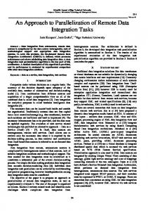
________________________________________________________________________________________________ Volume 43 Tratt [22] investigates different approaches to model context. This will allow modifying the current transformations. Particularly, attention is paid to OMG’s model without changing non-standard elements; Queries/Views/Transformations (QVT) [23]. Tratt [22] also c. Define output model, which helps to avoid reviews problems of tracing activities and models transformation within the same model, so called conformance, when the changes are made on the both sides – in-place transformation; source model and target model. Unification of declarative and d. Define transformation direction (from source imperative issues on model transformations is proposed by model representing traditional software adopting new approach to model transformations. It is capable development, to the output, representing modelof providing a flexible, efficient, and practical platform for driven software development). In mediniQVT creating model transformations, which can be re-used in tool the transformation direction is defined relation to SPEM. General Standard Software Process is dynamically, in Run Configurations screen. applied to MDA in SPEM within MASTER project [24]. It Rationale: by defining QVT transformation rules for SPEM provides standard workflows and activity model using SPEM models based in Ecore, it is possible to link and formalize so 1.0. Therefore SPEM can be utilized as a general meta-model called “traditional” software development activities with for defining processes. Model-to-model transformations can model-driven ones. Every SPEM activity or workflow which be applied to SPEM models, like they are applied to business corresponds to base building block of the “traditional” process models according to MDA. But in the early versions software development process will be described from modelof SPEM there was a lack of formalization and layering was driven perspective. not supported. 3. QVT relations transformations executed successfully (no The QVT Relations language was suggested by authors of errors), and the output model generated; this paper for SPEM metamodel transformations in [25]. a. In case of errors – the execution trace should be The process meta-models integration and unification analyzed; problem is reviewed in [26]. This paper named “Processb. If needed – debugger perspective should be Centered Model Engineering” was written in 2001, however, activated and the program transformations since this time the problem became even more serious because should be checked in the run-time. of the different MOF implementations. Rationale: in order to use the output SDLC model in Software process modelling questions are investigated in practice, it must be correctly transformed from the source [27]. An essential work on the process meta-models is also model. Though, the correct definition of transformation does provided in [28]. not always guarantee that the output model is correct. Therefore, the model can be additionally validated by defining III. INTEGRATION SOLUTION FOR MODELLING TOOL OF SDLC OCL rules for some base building blocks where the sequence The sections below propose specific integration solution of activities described is important. The target is specified at runtime when invoking the design, using the Eclipse as a general platform. Additional transformation and is called the execution direction. For deliverable is partially implemented QVT rules. SPEM model transformation we are using unidirectional A. Process Definition for High-Level Transformation transformation, the direction of transformation is mdd. The steps below represent the process dynamical flow. The The link between the modelling tools, models and their number labels represent the goals (what happened when goal relationships within Eclipse platform is depicted on Fig. 1. has been achieved), and the letter labels represent the The whole process in more details is described in [25]. actions/tasks (actions which need to be performed). Rationale B. Requirements for the Modelling Process of every goal is explained. Different process architects can describe the same 1. SPEM v1.0/SPEM v2.0 Ecore metamodel defined and development process differently by creating distinct models. validated; The models can be well-formed, but at the same time useless a. Create metamodel using Sample Ecore Editor, or when it comes to defining QVT transformation rules for them b. Create metamodel using Graphical editor Ecore due to insufficient formalization level and ambiguities in Tools. transformation interpretation. That’s why additional Rationale: metamodels are abstractions for models, and they procedures should be followed. In order to handle and define the properties and domain constraints for the models. constrain the whole SPEM process modelling for organization Thus, before creating any SDLC models and defining and SPEM transformation processes, several requirements are transformations for them, there is a need to have metamodel defined under the solution offered in this paper. They are the created. This is a base for modeling process. following: 2. QVT relations transformations defined a. Copy all SPEM elements from source model to 1. The process architect represents the current software development process using the base building blocks target model (phases, activities, tasks and their (Open UP based process used as a source); relationships); 2. Elements, which are not possible to represent using base b. Define QVT Relations transformations for the building blocks should be placed into the model, and SPEM elements converted in a model-driven
62
Scientific Journal of Riga Technical University Computer Science. Applied Computer Systems
2010
________________________________________________________________________________________________ Open UP base building blocks
Eclipse
UMA model (XML) Custom building blo cks
Volume 43
UMA-to-Ecore transformatio n
EPF Composer
SPEM model for “traditional development”
Ecore model (XML) Ecore model (XML)
SPEM model for MDA-based development”
mediniQVT
QVT transformation rules
Fig. 1. SPEM model integration schema for Eclipse
linked with existing building blocks. It means that all the process building blocks should be linked together – at least one link for the element must exist; 3. To avoid incorrect interpretation of the elements and ease the understanding of concepts – both base building block names and software development organization’s identified element names should be used. This allows unifying terminology and different naming descriptions for the same elements. In this paper any software development process model, which represent the process used in organization with the help of Open UP base blocks and which should be transformed to the model-driven software development process model, is called openup. The model, which represents the target process model and model-driven software development process, is called mda. These names are used for identifying, respectively, the source and the target models in the QVT Relations transformations. Both models are expressed in SPEM notation, and conform to SPEM metamodel. The metamodel used for the representing SPEM models is EMF Ecore. It is an Eclipse
1. .*
ProcessDefinitionElement
metamodel, used to describe models and runtime support [32]. For SPEM model transformation we are using unidirectional transformation, the direction of transformation is mda. C. UMA to Ecore SPEM Mappings in Eclipse SPEM implementation in Eclipse is called EPF (Eclipse Process Framework). While SPEM is just a metamodel specification and OMG provides no information regarding its usage, EPF is an extensible framework and tool set for software process engineering - method and process authoring, library management, configuring and publishing a process. It also covers process content for a range of software development and management processes supporting iterative, agile, and incremental development [31]. The main process modelling tool in Eclipse is called EPF Composer. It is a tool, aimed to produce a customizable software process engineering framework. Since one of our goals is to integrate process model into the transformation tool mediniQVT, we would need to take into account the metamodel properties.
0..*
includes
0.. * Guidance
ArtifactKind
WorkIt em
WorkDefinition
ActivityKind
Iteration
RoleKind
Condition
Goal
Precondition
Phase
ProcesComponent
Lifecycle
Fig. 2. UMA metamodel for Eclipse EPF
63
Scientific Journal of Riga Technical University Computer Science. Applied Computer Systems
2010
________________________________________________________________________________________________ Volume 43 Once the model is defined in the EPF, it can be exported to In similar way, all other transformations for relating the external file in XML format. The Eclipse package in which traditional SDLC base building blocks with model driven base EPF Composer models are stored is called UMA: elements are defined. org.eclipse.epf.uma. Since the mediniQVT is dealing with the models in Ecore, 1 Work Product Work Product Kind 0..* the adjustment of the model to the Ecore format is required. SPEM elements in Ecore belongs to eClassifiers class, type 0..* 0..1 is specified as an attribute parameter EClass. Element name is Process Pr ocess Role Per former also specified as an eClassifiers attribute parameter. The linkage with the elements is defined using eStructuralFeatures 0..* tag. For more information on the Ecore refer to the metamodel 0..* 0..* definition [32]. Activity Step 1 UMA defines a method library as a root container for all Work method elements [31]. All containing elements are associated Definition by composition and stored in a single XMI file. In case of UMA models, Ecore extension can be used for querying unidirectional associations in the reverse direction. It allows to Iteration Phase Lifecycle get, e.g., the list of tasks for the desired role. Additionally, when some real UMA models are exported from EPF 0..1 Composer, they contain excessive details like descriptions and 0..* Model Element Process links to external documents. This kind of information is not needed in the QVT structural transformations, and therefore, Process can be omitted in the model. 1..* Component 0..*
D. UMA and SPEM Metamodel Integration Because of the differences in the metamodels between SPEM and UMA, a mapping between them is needed in case we are using external models specified in SPEM. Fig. 2 describes the metamodel for UMA. Fig. 3 describes the simplified metamodel for SPEM, since SPEM has more expressiveness which we are not using, comparing to UMA. UMA contains fewer packages than SPEM 2.0. It has been designed from SPEM 2.0 to fit with EPF Composer [33]. Table 1 provides element mapping between the UMA and SPEM elements. Since not all the elements and their relations in the metamodel can be unambiguously mapped, the suggested substitute name from the same metamodel is defined in the brackets. E.g., for SPEM element “Step” there is no corresponding element in the UMA. However, according to the SPEM metamodel, “Activity” is a generalization for “Step”. Therefore, in UMA it is marked as “subset of ActivityKind”, because “ActivityKind” in UMA corresponds to “Activity” in SPEM. Three elements from UMA are not mapped – in SPEM they are defined as attributes for links, and are not relevant here. E. QVT Relations Transformation Example An example of SPEM to SPEM QVT Relations transformation is provided below – see Fig. 4. Both source model openup and target model mdd belongs to the same metamodel SPEM, which is expressed in Ecore format. There are two top relations: the first one, called DrawBP2CreateBPmodel, changes the name attribute for activity “Draw business process diagram”. The second one, CopyActivities – makes a copy for all activities from the source model to the target model, in case they are not explicitly defined like activity “Draw business process diagram”. This constraint is set up in when section.
64
1 Guidance Kind 0..*
Guidance
Discipline
Fig. 3. Simplified SPEM metamodel TABLE 1 SPEM AND EPF METAMODEL ELEMENT MAPPING SPEM
UMA
Work Definition
Work Definition
Iteration
Iteration
Phase
Phase
Lifecycle
Lifecycle
Process
(subset of Process Component)
Discipline
(subset of Process Component)
Process Component
Process Component
Activity
ActivityKind
Step
(subset of ActivityKind)
Process Performer
RoleKind
Process Role
(subset of RoleKind)
Guidance
(subset of Guidance)
Guidance Kind
Guidance
Model Element
Process Definition Element
Work Product
WorkItem
Work Product Kind
(generalization of WorkItem)
-
Condition
-
Precondition
-
Goal
Scientific Journal of Riga Technical University Computer Science. Applied Computer Systems
2010
________________________________________________________________________________________________ Volume 43 transformation SPEMtoSPEM(openup:SPEM, mdd:SPEM) formalization of architect knowledge using QVT rules, and { providing the ready-to-apply software development life cycle -- Copy source activity to target, changing the model. activity name, There are various tools available, which supports software -- occurs only for Initial phase development process modelling. Though, there are no unified top relation DrawBP2CreateBPmodel { integration mechanisms and interfaces defined between these tools. Generally, capabilities of model exporting and their checkonly domain openup p:Activity{ usage in legacy tools are limited due to different tool name = “Draw business process diagram”; standardizations, which raise a natural usability problem. owningPhase = "Initial"; Integration solution proposed is designed using Eclipse }; enforce domain mdd s: Activity { platform, which is highly adopted by the software engineering name = “Create business process model” community. SPEM is used as a metamodel for software }; development. SPEM is one of the MDA standards, defined by OMG. } The paper presents the results of investigation on how to -- Copy activity from source to target when it integrate modelling and transformation tools together in order is not base activity to handle SPEM model transformations in the Eclipse. The top relation CopyActivities outcomes of the work are: { • Tool integration design based on EMF; theName: String; • Eclipse platform based solution prototype description; checkonly domain openup p:Activity{ • Partially implemented QVT Relations transformation name = theName rules. }; Unfortunately, OMG standards are used as a baseline when enforce domain mdd s: Activity { developing custom modelling tools and extending standards. name = theName Developers are adding additional functionality and }; when enhancements to these tools, which makes impossible to re{ use the models without transforming models expressed in not DrawBP2CreateBPmodel(p,s); XML. E.g., the models created with EPF are not fully SPEM }} compliant. Even the metamodel implementation can be Fig. 4. SPEMtoSPEM QVT Relations example different (SPEM implementation in Ecore and UMA). It raises additional problems for transformation tools like mediniQVT. F. Limitations REFERENCES The solution proposed in this paper is limited to the [1] A. Kleppe, J. Warmer, and W. Bast, MDA Explained: The Model integration within the Eclipse platform only. It is not able to Driven Architecture: Practice and Promise. USA: Addison Wesley, solve one of the most essential problems – how to integrate the 2003, 192 p. SPEM model to and from any tool. In order to integrate every [2] “OMG model driven architecture,” Object Management Group. [Online]. Available: http://www.omg.org/mda. [Accessed: September modelling tool which is using SPEM as a metamodel, we 2009]. would need to define the transformation chain for every [3] O. Nikiforova, A. Cernickins, and N. Pavlova, “Discussing the difference between model driven architecture and model driven unique format used by the modelling tools. development in the context of supporting tools,” in The Fourth However, with some rework, the concepts presented in this International Conference on Software Engineering Advances (ICSEA) paper can be applied to any software development process 2009. Porto, Portugal: IEEE Publishing House Ltd., 2009, pp. 1-6. modelling tool. [4] K. Leopold, “Tool support for model driven development; both commercial products and scientific prototypes,” Switzerland, Zurich: Even if we use unified metamodel, it can be expressed in University of Zurich, Department of Computer Science. [Online]. a different manner, depending on the implementation. The Available: http://seal.ifi.uzh.ch/fileadmin/User_Filemount/Vorlesungs_ same model developed in different tools can correspond to Folien/Seminar_SE/SS07/SemSE07-Kevin_Leopold.pdf. [Accessed: February 2010]. different data type definition (DTD), therefore, additional type [5] UML forum. UML modeling tools. [Online]. Available: transformations are required. http://www.uml-forum.com/tools.htm. [Accessed: February 2010]. [6]
IV. CONCLUSIONS SPEM integration into the transformation tool supporting QVT is not a trivial task, since there is no single unified standard which could be used for models interchange, and different standards requires unification. Practical goal of the developing SPEM models for “traditional” SDLC and transforming them to the modeldriven software development lifecycle model is process of
[7]
[8]
“60+ UML tools help you design workflow easily,” Ntt.CC. [Online]. Available: http://ntt.cc/2009/11/29/60-uml-tools-help-you-designworkflow-easily.html. [Accessed: February 2010]. O. Nikiforova, A. Cernickins, and N. Pavlova, “On the tool chain for model driven architecture and model driven development: drawing a distinction,” in The 13th East-European Conference on Advances in Databases and Information Systems (ADBIS), September 2009. Riga, Latvia: JUMI Publishing House Ltd., 2009, pp. 408-415. O. Nikiforova, V. Nikulsins, and U. Sukovskis, “Integration of MDA framework into the model of traditional software development,” in Selected Papers from the Eighth International Baltic Conference Baltic DB&IS 2008, H.-M. Haav and A. Kalja, Eds., Series “Frontiers in
65
Scientific Journal of Riga Technical University Computer Science. Applied Computer Systems
2010
________________________________________________________________________________________________ [9]
[10]
[11]
[12]
[13]
[14]
[15] [16] [17] [18]
[19]
[20]
[21]
[22]
[23]
Artificial Intelligence and Applications", Databases and Information Systems V. IOS Press, 2009, pp. 229-242. V. Nikulsins, O. Nikiforova, and U. Sukovskis, “Mapping of MDA models into the software development process, databases and information systems,” in Proceedings of the Eighth International Baltic Conference Baltic DB&IS 2008, Tallinn, Estonia, June 2-5, 2008, H.-M. Haav and A. Kalja, Eds. Tallinn: Tallinn University of Technology Press, pp. 217-226. V. Nikulsins and O. Nikiforova, “Adapting software development process towards the model driven architecture,” in Proceedings of The Third International Conference on Software Engineering Advances (ICSEA), International Workshop on Enterprise Information Systems (ENTISY), Sliema, Malta, October 26-31, 2008, H. Mannaert, C. Dini, T. Ohta, and R. Pellerin, Eds. Published by IEEE Computer Society, Conference Proceedings Services (CPS), pp. 394-399. V. Nikulsins, O. Nikiforova, and U. Sukovskis, “Analysis of activities covered by software engineering discipline”, in Seventh International Baltic Conference on Databases and Information Systems, Communications, Materials of Doctoral Consortium, O. Vasilecas, J. Eder, and A. Caplinskas, Eds. Vilnius, Lithuania: VGTU Press “Technika” scientific book No. 1290, 2006, pp. 130-138 V. Nikulsins and O. Nikiforova, “Software development teams organization,”” in Scientific Proceeding of Riga Technical University, 5th Series, Computer Science, Applied Computer Systems, Vol. 26, 2006, pp. 54-65. “Software process engineering meta-model specification (SPEM) version 2.0,” Object Management Group. [Online]. Available: [Accessed: http://www.omg.org/cgi-bin/doc?formal/08-04-02.pdf. September 2009]. “Capability maturity model integration (CMMI),” Software Engineering Institute. [Online]. Available: http://www.sei.cmu.edu/cmmi. [Accessed: September 2009]. P. Kruchten, The Rational Unified Process: An Introduction, 2nd ed. USA: Addison Wesley, 2000. ISO – International Organization for Standardization. [Online]. Available: http://www.iso.org. [Accessed: September 2009]. IEEE Standards Association. [Online]. Available: http://standards.ieee.org. [Accessed: September 2009]. E. Breton and J. Bezivin, “Process-centered model engineering,” Nantes University, France. [Online]. Available: http://www.sciences.univnantes.fr/lina/atl/www/papers/edoc.pdf. [Accessed: September 2009]. B. Combemale and X. Cregut, “Towards a rigorous process modeling with SPEM,“ Rennes University, France. [Online]. Available: http://www.combemale.net/research/phd/2006/iceis250406-CCCCposter401.pdf. [Accessed: September 2009]. “Object constraint language specification version 2.0,” Object Management Group. [Online]. Available: http://www.omg.org/cgibin/doc?formal/06-05-01.pdf. [Accessed: September 2009]. Y. Feng, L. Mingshu, and W. Zhigang, “SPEM2XPDL: towards SPEM model enactment.” Bejing, China: The Chinese Academy of Sciences, 2006. L. Tratt, “Model transformations and tool integration,” Department of Computer Science, King’s College London. London: Springer-Verlag, 2004. “Meta object facility (MOF) 2.0 Query/View/Transformation v1.0,” Object Management Group. [Online]. Available: http://www.omg.org/cgi-bin/doc?formal/08-04-03.pdf. [Accessed: September 2009].
Volume 43
[24] “Model-driven Architecture inSTrumentation, Enhancement and Refinement: MASTER. Process model to engineer and manage the MDA approach,” European Software Institute, Spain, 2003. [Online]. Available: http://modeldrivenarchitecture.esi.es/pdf/DeliverableD32.zip. [Accessed: September 2009]. [25] V. Nikulsins and O. Nikiforova, “Transformations of SPEM models using query/view/transformation language to support adoption of modeldriven software development lifecycle,” in The 13th East-European Conference on Advances in Databases and Information Systems (ADBIS), September 2009. Riga, Latvia: JUMI Publishing House Ltd., 2009. [26] E. Breton and J. Bezivin, “Process-centered model engineering,” in Fifth IEEE International Enterprise Distributed Object Computing Conference, 2001. France: IEEE, 2001. [27] S. T. Acuna and X. Ferre, “Software process modeling,” Departamento de Lenguajes y Sistemas Informaticos e Ingenieria del Software, Spain. [Online]. Available: http://is.ls.fi.upm.es/xavier/papers/processmodel ling.pdf. [Accessed: September 2009]. [28] E. Breton and J. Bezivin, “An overview of industrial process metamodels,” ICSSEA, France, 2000. [Online]. Available: http://atlanmod.emn.fr/www/papers/icssea2.pdf. [Accessed: September 2009]. [29] Open unified process (OpenUP), Eclipse Foundation. [Online]. Available: http://epf.eclipse.org/wikis/openup. [Accessed: September 2009]. [30] Medini QVT, ikv++ technologies ag, Germany. [Online]. Available: http://projects.ikv.de/qvt. [Accessed: September 2009]. [31] Eclipse process framework (EPF), Eclipse Foundation. [Online]. Available: http://www.eclipse.org/epf. [Accessed: September 2009]. [32] Eclipse modeling framework project (EMF), Eclipse Foundation. [Online]. Available: http://www.eclipse.org/modeling/emf. [Accessed: September 2009]. [33] A. Garcia, et al., “topPPROCESS. A process model driven approach applied in TOPCASED for embedded real-time software,” Rennes University, France. [Online]. Available: http://www.combemale.fr/ research/phd/2008/erts08-GCCGL.pdf. [Accessed: September 2009].
Vladimirs Nikulsins is a doctoral student of Riga Technical University. He is graduated to master degree in Computer Science and Information Technology, Institute of Applied Computer Systems, Faculty of Programming, from Riga Technical University (Riga, Latvia) in 2006. Vladimirs Nikulsins is working as SAP Consultant on interfaces in Accenture Riga Delivery Centre. Oksana Nikiforova has received engineering science doctor’s degree (Dr.sc.ing) in information technologies sector (system analysis, modeling and designing, sub-sector) from the Riga Technical University, Latvia, in 2001. She is presently an Associated Professor in the Department of Applied Computer Science of Riga Technical University, where she has been on the faculty since 1999. Her current research interests include object-oriented system analysis and modelling especially its issues in the framework of Model Driven Architecture. In these areas she has published extensively and has been awarded several grants. She has participated and managed several research projects related to the system modeling, analysis and design, as well as participated in several industrial software development projects.
Vladimirs Ņikuļšins, Oksana Ņikiforova. Rīku integrācija SPEM modeļu transformāciju nodrošināšanai Eclipse vidē Šajā rakstā ir piedāvāta pieeja SPEM modelēšanas rīku integrēšanai ar Query/View/Transformation (QVT) rīkiem izmantojot Eclipse Modeling Framework (EMF). Rīku integrācijas mērķis ir modeļvadāmas arhitektūras ieviešana kompānijās, kas fokusējas uz tā saucamām „tradicionālām” programmatūras izstrādes paņēmieniem. Programmatūras izstrādes dzīves ciklam ir jābūt aprakstītam ar valodu OMG SPEM. Šajā rakstā piedāvātā pieeja balstās uz modeļvadāmās integrācijas izmantojot EMF-bāzētus interfeisus, kas palīdz savienot MOF bāzētus Ecore modeļus ar QVT transformācijas rīkiem. Darba gaitā tiek izstrādāti sekojošie artefakti: (i) EMF bāzēta rīku integrācija (ii) risinājuma prototips Eclipse videi (iii) QVT Relations transformācijas likumi. Modeļu transformācijas ir veiktas ar mediniQVT rīku, kas ļauj strādāt ar modeļiem, tādiem kā Ecore definētiem metamodeļiem, kā arī piedāvā atkļūdošanas un likumu trasējamības iespējas. QVT Relations transformācijas tiek pielietotas attiecībā uz avota modeli, kas atbilst tradicionālam programmatūtas izstrādes dzīves ciklam. Šīs transformācijas rezultāts ir jauns programmatūras izstrādes process, kas atbilst modeļvadāmam programmatūras izstrādes procesam. Izveidots mērķa modelis ir SPEM atbilstošs, un var būt ieimportēts vairākos SPEM atbalstāmos ārējos rīkos. Владимир Никульшин, Оксана Никифорова. Интеграция программных инструментариев для обеспечения трансформации SPEM моделей в среде Eclipse. В данной статье предлагается подход для интеграции программных инструментариев моделирования с помощью средств Query/View/Transformation (QVT) в среде Eclipse Modeling Framework (EMF). Цель интеграции программных инструментариев – обеспечение внедрения Model Driven Architecture внутри организации, пока что использующей так называемые “традиционные” способы разработки программного обеспечения.
66
Scientific Journal of Riga Technical University Computer Science. Applied Computer Systems
2010
________________________________________________________________________________________________
Volume 43
Подразумевается что жизненный цикл процесса разработки программного обеспечения должен быть отображен с помощью языка OMG SPEM. Научный подход предоставленный в данной статье основан на интеграции моделей при помощи EMF интерфейсов, что помогает связать MOF модели базирующиеся на Ecore со средствами трансформации QVT. Результатами работы являются: (i) схема интеграции основанная на EMF (ii) прототип решения для среды Eclipse (iii) правила трансформации QVT Relations. Сама трансформация моделей осуществляется при помощи средства mediniQVT, который позволяет работать с моделями описанными как метамодели Ecore и предоставляет возможности отладки и трассировки. QVT Relations трансформации применяются относительно исходной модели, соответствующей т.н. “традиционному” жизненному циклу разработки программного обеспечения. Результатом такой однонаправленной трансформации является новый процесс разработки, который соответствует процессу разработки MDA. Полученная в результате трансформации модель основывается на стандарте SPEM, и может быть загружена во внешние средства моделирования поддерживающие SPEM модели описанные с помощью Ecore.
67