International Archives of the Photogrammetry, Remote Sensing and Spatial Information Sciences, Volume XXXVIII-4/C21
TOWARD ACCESSING SPATIAL STRUCTURE FROM BUILDING INFORMATION MODELS Carl Schultz and Mehul Bhatt SFB/TR8 Spatial Cognition, University of Bremen P.O. Box 330 440, 28334 Bremen, Germany
[email protected],
[email protected] Commission IV/WG 8 KEY WORDS: Architecture, Analysis, Modelling, Artificial Intelligence, Spatial, Technology
ABSTRACT: Data about building designs and layouts is becoming increasingly more readily available. In the near future, service personal (such as maintenance staff or emergency rescue workers) arriving at a building site will have immediate real-time access to enormous amounts of data relating to structural properties, utilities, materials, temperature, and so on. The critical problem for users is the taxing and error prone task of interpreting such a large body of facts in order to extract salient information. This is necessary for comprehending a situation and deciding on a plan of action, and is a particularly serious issue in time-critical and safety-critical activities such as firefighting. Current unifying building models such as the Industry Foundation Classes (IFC), while being comprehensive, do not directly provide data structures that focus on spatial reasoning and spatial modalities that are required for high-level analytical tasks. The aim of the research presented in this paper is to provide computational tools for higher level querying and reasoning that shift the cognitive burden of dealing with enormous amounts of data away from the user. The user can then spend more energy and time in planning and decision making in order to accomplish the tasks at hand. We present an overview of our framework that provides users with an enhanced model of “built-up space”. In order to test our approach using realistic design data (in terms of both scale and the nature of the building models) we describe how our system interfaces with IFC, and we conduct timing experiments to determine the practicality of our approach. We discuss general computational approaches for deriving higher-level spatial modalities by focusing on the example of route graphs. Finally, we present a firefighting scenario with alternative route graphs to motivate the application of our framework. 1
INTRODUCTION
Consider the following scenario. A fire has broken out in a factory and the firefighting service crew are enroute to the scene of the incident. During the minutes of travelling from the fire station to the factory site, information is relayed from the communication centre (which is in direct contact with people at the site) to the firefighting crew members. At this early stage, information is vital for the fire chief and subordinate crew members to develop an impression of the incident, form expectations, and begin to formulate potential plans of action (Landgren, 2004). In the near future it is feasible that electronic design plans of the site along with enormous amounts of real-time building data could be transmitted wirelessly to the fire crew. The potential for enhancing the firefighters’ comprehension of the incident, thereby increasing their capacity to act effectively (Landgren, 2006), 1 is immense, through the availability of detailed design plans, real-time temperature and other sensor measurements, video feeds, detecting compromised structural components such as beams and floors, predicting flashover, and so on. This type of data is becoming readily available; the key issue is how to provide the firefighters with access to the relevant information that can be derived from these available facts. Similar data can be made available for a wide range of service tasks including maintenance and construction, and municipalities and government-level decision makers. For example, effective querying and reasoning tools for both historical and real-time building data can be used to identify energy-use patterns, infer the source of drafts, identify plumbing faults and leaks, identify 1 In
particular, refer to the sections on Situation Assessment (page 205), and Situational Adjustment (page 206).
electrical faults, detect warning signs of structural damage from stress or rot, early signs of fire hazards such as rising temperatures, gas leaks, heating devices such as ovens being left on in unusual conditions, and so on. In all cases, real-time access to building data can dramatically enhance the effectiveness of the decisions being made, and thus have a greatly positive effect on society. Large scale initiatives for developing standard unifying building models, such as CityGML (Kolbe et al., 2005) and the Industry Foundation Classes (IFC) (Froese et al., 1999) have matured to the point of being widely employed in commercial applications such as ArchiCAD (Graphisoft Inc., 2010). More specifically, the paradigm of building information models (BIM) (Eastman et al., 2008) is now well established. BIM explicitly represents building feature instances based on a specialised building-domain ontology, geometric spatial relationships, some basic qualitative spatial relationships (such as the connectivity between particular building elements), and allows the representation and calculation of relevant quantities such as areas, volumes, dimensions, weight, and so on. Research on employing building data to reason about domainspecific phenomena is of course not new. Ray tracing simulations predict the distribution of lumens through a space (Larson and Shakespeare, 1998), mathematical models have been developed to predict the development of fires (Gupta, 1994) and flashover (McCaffrey et al., 1982), and rules have been developed for predicting crowd behaviour (Bitgood, 1992). However, these approaches tend to be highly specialised, disconnected (i.e. relying on significantly different mathematical models of phenomena, and specialised models of a building), and can
28th Urban Data Management Symposium (UDMS 2011), September 28-30, 2011, Delft, The Netherlands
25
International Archives of the Photogrammetry, Remote Sensing and Spatial Information Sciences, Volume XXXVIII-4/C21
not directly support each other nor the integration of new simulation algorithms. Furthermore, these approaches often operate at a particular (highly detailed) level of granularity, require considerable computational resources, and very typically require detailed numerical data that may not be available. The key component that is missing is an enhanced, qualitative building model that intelligently abstracts from the available data to provide powerful spatial modalities, that is, alternative perspectives of “space” and spatial information. These spatial modalities can then provide a unifying foundation for defining domainspecific concepts and inference rules that greatly assist in accomplishing the user’s tasks. In this paper we present a framework that provides an enhanced model of “the built-up space”; this enables software developers and users to incorporate broader notions of spatial structure and spatial relationships when defining rules and queries, which go beyond the physical shape of objects. In the following section we discuss the concept of spatial modalities. We then focus on the technical aspects required to derive and employ spatial modalities from real building data with the example of route graphs. We then present the conclusions of the paper. 2 ALTERNATIVE PERSPECTIVES OF SPACE: SPATIAL MODALITIES DERIVED FROM SPATIAL ARTEFACTS In essence, having effective information access of built environments is being able to get answers to questions about a design that enable the decision makers to generate plans of action for accomplishing the task at hand. The critical requirement for timely access of information about spatial structure is being able to quickly and easily 1. specify relevant questions, and 2. interpret the answers. Using a description of physical spatial structure in purely geometric object-orientated terms does not meet this requirement. We are primarily interested in being able to derive more abstract and cognitively useful patterns and structures in a design that go beyond the physical bodies of objects, based solely on the given physical structure. We do this with a unifying concept of spatial artefacts (Bhatt and Freksa, 2010): three-dimensional regions of seemingly “empty” space2 that in fact have semantics based on the configuration and semantics of objects in the design. Specifically, we use a geometrically grounded object-oriented building information model to identify shapes, sequences, and patterns that are meaningful to the user with respect to the way that objects and empty space are organised. We are thus aiming to formalise spatial concepts which capture the deeper sense of an arrangement of objects, and which are sufficiently flexible to handle a variety of application domains. Examples of prominent spatial concepts and the underlying spatial artefacts are as follows: 1. The relationship between movement through free space and connectedness: based on movement spaces. 2. The different notions of visibility, and the conditions under which an object is visible, based on straight line relationships, occlusion, distance, and other aspects: based on visibility spaces. 2 Spatial
artefacts are “empty” regions of space in the sense that they do not have a material extension.
3. The grouping of objects and spaces into structural and semantic hierarchies: based on containment spaces and partof spaces. 4. Focusing specifically on the ways in which a physical environment gives meaning to regions of empty space: performing certain functions, undergoing operations, and sensing the environment. 5. The relationship between structures and occupant flow; i.e. how spatial structure impacts path decisions and movement: combination of spatial artefacts, including all of the above. It is the interaction between these various modalities (all of which are derived using the unifying concept of spatial artefacts), and the ability to formulate first-order rules and queries that seamlessly refer to different modalities, that gives rise to an enhanced BIM. In ongoing research we are addressing all of these aspects (Bhatt et al., 2011); in this paper we are focusing on the problem of deriving varieties of route graphs (which model movement through space) from real building design data. 3
EXTENDING BUILDING INFORMATION MODELS OF INDOOR SPACE
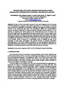
In this section we describe the technical details of extending a BIM with spatial modalities. Figure 1 illustrates an overview of the framework.3 During an application session the BIM is used to derive spatial modalities (either online or offline, depending on the specific application requirements) which are used for querying, for example, by selecting a subset of the BIM model and spatial modalities that satisfies a given first-order expression; the persistence of the derived modalities also depends on the application, for example, the modalities could be volatile in cases where the BIM model is undergoing frequent changes, or the modalities could be permanently archived along with the BIM when no further changes to the BIM are possible. These layers decouple the higher-level reasoning from the geometric object-oriented building model (as opposed to directly integrating spatial modalities into the BIM) and keep the overall framework modular. Thus, the framework does not depend on any particular BIM, or BIM interface (such as the BIMserver project (BIMserver, 2011)). 3.1
Extracting Object Placement and Shape
We employ IFC (Froese et al., 1999) as a realistic case of a building model ontology. IFC is large and comprehensive, with the intention of covering all aspects of a built environment including design, construction, and use. Deriving spatial modalities only requires a fragment of the complete IFC specification, namely object types, their placement, shape representations, and relationships with other objects. With respect to shape, IFC supports numerous 2D and 3D modelling approaches such as profile extrusion, sweeps, CSG and b-rep. It is necessary to devise a homogenous approximation of object representations that is just sufficiently complex to derive the required modalities. We do this by firstly projecting the 3D representations on to a 2D plane parallel to the ground, annotated with the floor number. Object shape representation is then approximated as: 1. the bounding line segment for large area-based objects such as spaces and slabs, as illustrated in Figure 2; 3 Rounded-rectangles represent data models, ellipses represent processes, rectangles represent interfaces, and arrows represent the flow of information.
28th Urban Data Management Symposium (UDMS 2011), September 28-30, 2011, Delft, The Netherlands
26
International Archives of the Photogrammetry, Remote Sensing and Spatial Information Sciences, Volume XXXVIII-4/C21
Query Interface
(e.g. Architectural Design Tool)
Spatial Modalities
Figure 2: Extracting the representation of a room from an IFC model.
(e.g. specialised route graph)
Derive Modalities BIM Interface (e.g. BIMserver)
BIM (e.g. IFC)
Figure 3: Deriving a 2D representation of a museum display cabinet from a 3D IFC b-rep model containing 1333 vertices.
Figure 1: Overview of the spatial modalities framework. 2. heterogeneous, object-based partitions. Table 1: Comparison of vertex count used to represent shapes in BIM, 2D projection, convex hulls, and time taken to parse an IFC STEP file and compute convex hulls and bounding boxes (repeated 100 times for each object).
Object
Desk Cabinet Door Telephone Sphere Laptop Chair Wide Cabinet
3D model vertices
Vertices after 2D projection
Vertices in 2D convex hull
Time to get convex hull 100x (seconds)
157 1333 1396 1560 3168 4140 7994
19 52 70 220 325 591 803
6 24 5 5 37 12 25
1 5 6 9 23 41 106
Time to get bounding box 100x (seconds) 1 2 2 2 4 7 10
10868
1180
73
211
14
2. either the convex hull or the (object aligned) bounding box of all other objects including walls, doors, windows, openings, and furniture, as illustrated in Figure 3.4 These approximations substantially reduce the vertices required to express the form of an object by orders of magnitude, while retaining and emphasising the salient geometric aspects necessary for computing the modalities. A comparison of some standard 3D object models is shown in Table 1. The time to compute the approximating shape 100 times is given to highlight the practicality of the approach.5
3.2
Internal Data Structures for Deriving Spatial Modalities
The geometric data structures used to derive spatial artefacts and modalities can be broadly categorised as using either 1. uniform, object-independent partitions, or 4 The choice between convex hull and bounding box depends on the context of the application. 5 Experiments were run on a MacBookPro, OS X 10.6.3, 2.66 GHz.
An example of a uniform partition approach is occupancy grids (Moravec and Elfes, 1985), where a grid of uniformly sized cells is overlaid on the building design; the contents of each cell and its neighbours can be used to generate route graphs (Li et al., 2009). Another example of uniform partitions is when ray tracing is performed by firing rays from a source object at regular angular intervals; this can be used to approximate occlusion and visibility. The appeal of uniform approaches for generating the spatial modalities that we are interested in is that the computational complexity does not grow too rapidly with a more complex design (i.e. a constant number of cells are used in a grid, or a constant number of rays are fired, regardless of the number of objects in a design). Moreover, in the case of route graphs, one intuition is that a more coarse, lower-granularity route graph that highlights the general skeleton of a building can be computed using a coarser occupancy grid; the idea is that the core structural features such as major walls and columns will be physically larger than, for example, furniture and other objects that can be easily moved around. Unfortunately we have found that this is not the case in general, and that uniform approaches suffer from issues of scalability when used to derive the spatial modalities. Many features that structurally appear to define the prominent topological skeleton of a design can be relatively thin (for example, the walls that delineate the authors’ offices from a long stretch of corridor are only 8cm thick). In these cases where the relevant objects are sparse and small, uniform approaches completely break down: partitions are either too inclusive, too exclusive, or the partitions are so small and numerous that computation becomes intractable. Alternatively, we employ an approach of partitioning space based on the objects that are present in a design. With respect to route graphs, regions of movement space can be defined as geometric regions that do not overlap certain “obstacle” objects, where different first-order conditions that define whether an object is an obstacle give rise to alternative movement spaces. The following algorithm derives a set of movement spaces from a set of products (e.g. walls, doors, etc.) in a design by approximating product
28th Urban Data Management Symposium (UDMS 2011), September 28-30, 2011, Delft, The Netherlands
27
International Archives of the Photogrammetry, Remote Sensing and Spatial Information Sciences, Volume XXXVIII-4/C21
Figure 4: Floorplan of the museum.
Figure 6: Standard route graph of the museum. Algorithm: Derive route graph (design, M ) for each mr in M for each product p in design if p is visitable and p shape geometry intersects mr create route graph edge between p and mr
Figure 6 illustrates the route graph7 that is generated when IFC openings, doors, spaces and derived movement spaces are specified as visitable. 4
Figure 5: Movement spaces of the museum.
shape geometries as 2D polygons (as shown in the previous section) and then performing geometric region subtraction.6
Algorithm: Derive movement spaces (design, floor) m = initialise movement space region for each product p in design if p is on floor and p is obstacle subtract p shape geometry from m let M be an empty set for each region r (with zero or more holes) in m create a movement space mr and add to M return M
For example, consider the floorplan of a museum illustrated in Figure 4. We derive the movement spaces illustrated in Figure 5 by defining obstacles to be products with an IFC class type as either walls, doors, openings, or windows. Having derived a set of movements spaces, route graphs can then be generated by relating objects to the movement space regions, where different first-order conditions that determine when an object is visitable provide alternative route graphs. The following algorithm derives a route graph from a set of products in a design and a set of movement spaces. 6 Movement space m is initialised as the bounding box of the design. As the algorithm proceeds, m may contain holes, and may consist of multiple disconnected, concave (but non-self-intersecting) regions.
SPECIFYING HIGHER-LEVEL RULES AND QUERIES
The derivation of more abstract spatial modalities allows BIM to be used in a more intuitive, effective way, for example, by providing a more effective query interface and allowing the specification of qualitative high-level rules that refer to relationships in the modalities. Such intelligent IT-based tools can be used to resolve conflicting information at a qualitative level, assist in the maintenance of qualitative spatial information (Cohn and Hazarika, 2001), and suggest the most plausible description of a situation based on incomplete qualitative information. Consider firefighters navigating through a builiding in search of victims. The firefighters’ sense of orientation depends heavily on reference features such doors, walls, corners, and large pieces of furniture (Lindgren, 2004), and thus the standard route graph, as illustrated in Figure 7, does not provide the type of information that a firefighter needs when navigating through a building. A more effective, domain-specific route graph is defined by the arrangement of salient features such as doors and windows along room walls, as illustrated in Figure 8. This is derived by specifying the condition that movement space must be within the functional space of a wall. For example, compare the hypothetical view of the environment from the firefighters’ perspective as they enter the building through the door in the bottom right of the floorplan; Figure 9 illustrates the perspective under visible conditions, and Figure 10 illustrates low-visibility conditions. A spatial assistance navigation system could be mounted on each of the firefighter’s helmets with a small transparent display on the mask. The mask display lists the features of the room that are useful for orientation, ordered using the 7 The white circles represent route graph nodes and the lines connecting circles represent the logical spatially connected relation (i.e. the lines do not represent a geometric path between objects).
28th Urban Data Management Symposium (UDMS 2011), September 28-30, 2011, Delft, The Netherlands
28
International Archives of the Photogrammetry, Remote Sensing and Spatial Information Sciences, Volume XXXVIII-4/C21
Door: behind, left along wall (3x corner) Opening: left along wall
Window: right along wall (2x corner) Door: right along wall
Figure 7: Region-connectivity route graph of a building. Figure 10: Firefighter perspective in burning building with smoke-filled interiors; the specialised route graph is required for navigation assistance.
Window Window Door
Window
Door
¯¯¯¯¯¯¯˘
Opening
Door Door
Window
Door
Window
Window
Window
Figure 8: Specialised route graph based on the positioning of features along walls of room in a building. specialised route graph in Figure 8. The standard route graph can be used when the firefighters can move freely through the room, and when visibility is significantly reduced, the specialised route graph can be used for more effective for navigation, as the firefighters need to rely on walls for orientation. The path that leads to the nearest exits are displayed in white; the software application determines nearest exits using first-order rules e.g. nearestExit(x, f ) = connected(x, f )∧[exit(x)∨∃w.nearestExit(w, x)]. 5
information necessary for facilitating fast, flexible, cognitivelydriven querying and reasoning. Specifically, numerical values may not be available, for example, during the concept stage and the initial stage of a building design; the risk is that a team of architects may invest significant time and effort refining an initial design that has been specified in a more general, qualitative manner, that is ultimately physically inconsistent and thus impossible to realise. Furthermore, the information required by many tasks is not numerical quantities, nor the satisfaction of rules in the form of inequalities. Instead, many tasks require higher-level domain-specific information that involves abstract spatial concepts such as movement and visibility, and is tightly coupled to the semantics of the objects involved. We have shown that parsing real BIM data (in the form of complex IFC 3D object models) in order to derive spatial modalities is computationally practical, and we have discussed methods for computing high-level spatial modalities based on geometric and semantic BIM data. Moreover, the conditions used to derive spatial modalities are very flexible and can thus be customised to address application-specific domains; this was illustrated with a scenario in the domain of firefighting.
CONCLUSIONS
In this paper we have presented a framework that enables the formalisation of high-level spatial structure and directly supports users with qualitative spatial querying, thus addressing the limitations of standard BIM. While an object-oriented perspective of spatial structure provided by BIM is a powerful paradigm, standard building models fall short in providing the sorts of high-level
Door: behind, left along wall (3x corner) Opening: left along wall
Window: right along wall (2x corner) Door: right along wall
ACKNOWLEDGEMENTS We gratefully acknowledge the funding and support of the German Research Foundation (DFG), www.dfg.de/ – the work described in this paper has been conducted as part of the DFG funded SFB/TR 8 Spatial Cognition project [DesignSpace], www. sfbtr8.spatial-cognition.de/designspace.html. REFERENCES Bhatt, M. and Freksa, C., 2010. Spatial computing for design: An artificial intelligence perspective. In: NSF International Workshop on Studying Visual and Spatial Reasoning for Design Creativity (SDC’10). http://www.cosy.informatik.uni-bremen.de/staff/ bhatt/seer/Bhatt-Freksa-SDC-10.pdf.
Figure 9: Firefighter perspective with no smoke; the standard route graph is applicable for providing navigation assistance.
Bhatt, M., Schultz, C. and Freksa, C., 2011. The ‘space’ in spatial assistance systems: Conception, formalisation, and computation. In: T. Tenbrink, J. Wiener and C. Claramunt (eds), Explorations in Language and Space, Oxford University Press. BIMserver, 2011. Open source building information modelserver. http://bimserver.org/.
28th Urban Data Management Symposium (UDMS 2011), September 28-30, 2011, Delft, The Netherlands
29
International Archives of the Photogrammetry, Remote Sensing and Spatial Information Sciences, Volume XXXVIII-4/C21
Bitgood, S., 1992. Visitor orientation and circulation: some general principles. Visitor behavior 7(3), pp. 15. Cohn, A. and Hazarika, S., 2001. Qualitative spatial representation and reasoning: An overview. Fundam. Inf. 46(1-2), pp. 1–29. Eastman, C., Teicholz, P., Sacks, R. and Liston, K., 2008. BIM Handbook: A Guide to Building Information Modeling for Owners, Managers, Designers, Engineers and Contractors. Frontiers in Artificial Intelligence and Applications, Wiley. Froese, T., Fischer, M., Grobler, F., Ritzenthaler, J., Yu, K., Sutherland, S., Staub, S., Akinci, B., Akbas, R., Koo, B., Barron, A. and Kunz, J., 1999. Industry foundation classes for project management - a trial implementation. ITCon 4, pp. 17– 36. www.ifcwiki.org/. Graphisoft Inc., 2010. graphisoft.com/.
ArchiCAD 13.
http://www.
Gupta, A., 1994. Calfire: An interactive model for fire calculations. Fire Technology 30(3), pp. 304–325. Kolbe, T. H., Groger, G. and Plumer, L., 2005. CityGML interoperable access to 3d city models. In: Proceedings of the International Symposium on Geo-Information for Disaster Management, Springer Verlag. Landgren, J., 2004. Fire crew enroute sense-making in emergency response. In: ISCRAM04. Landgren, J., 2006. Making action visible in time-critical work. In: CHI ’06: Proceedings of the SIGCHI conference on Human Factors in computing systems, ACM, New York, NY, USA, pp. 201–210. Larson, G. and Shakespeare, R., 1998. Rendering with Radiance: The Art and Science of Lighting Visualization. Morgan Kaufmann, San Francisco, New York. Li, X., Claramunt, C. and Ray, C., 2009. A continuous-based representation for the analysis of indoor spaces. In: STAMI, pp. 44– 53. Lindgren, I., 2004. Communication and team performance - a field study of breathing apparatus firefighters’ communication during rescue operations. Master’s thesis, Linkpings universitet, Linkping. McCaffrey, B., Quintiere, J. and Harkleroad, M., 1982. Estimating room temperatures and the likelihood of flashover using fire test data coorelations. Fire Technology 18, pp. 122–122. 10.1007/BF02993495. Moravec, H. and Elfes, A., 1985. High resolution maps from wide angle sonar. In: Robotics and Automation. Proceedings. 1985 IEEE International Conference on, Vol. 2, pp. 116 – 121.
28th Urban Data Management Symposium (UDMS 2011), September 28-30, 2011, Delft, The Netherlands
30