VHDL source code for fault localization. If we are interested in .... Each process contains a so called sensitivity list enumerating those signals the process ..... [15] Raymond Reiter, 'A theory of diagnosis from first principles', Artificial. Intelligence ...
Towards a Model for Automated Fault Localization in VHDL Designs: Exploring Counterexample-Traces Using a Model-Based Diagnosis Approach Bernhard Peischl and Franz Wotawa1 Technische Universit¨at Graz Institute for Software Technology (IST) Inffeldgasse 16b/2, A-8010 Graz, Austria {peischl,wotawa}@ist.tu-graz.ac.at Abstract. In this paper we discuss the exploration of a model checker’s counterexample trace using model-based debugging techniques. We show that a diagnosis model obtained from a single counterexample run in an event-driven simulation is not appropriate for localizing a failures real cause in general. Notably, modeling VHDL’s event and process semantics as originally defined hampers the integration of today’s model checkers with our event-centered diagnosis approach considerably. Therefore, we propose a static but still event-centered and a data-driven approach for debugging hardware description languages. Both models do not exhibit the restrictions of the event-driven simulation approach with respect to integration of model checking tools.
1
Introduction
Detecting, localizing, and fixing faults is a crucial issue in today’s fast paced and error prone development process. Detecting and repairing misbehavior in an early stage of the development cycle reduces costs and development time considerably. Among the most popular techniques in detecting misbehavior of designs are model checking and testing. Today’s testing procedures have reached a high state of maturity [2], and model checking [12] particularly helps in revealing the violation of properties even in unusual situations where bugs are difficult to detect. Both approaches, model checking and testing, have in common that they exploit a partial specification (a test case or a property) for detecting a possible fault. Symbolic model checking automatically verifies whether a design satisfies a given property. The more traditional method of testing requires a test bench, that is, predefined input sequences and the associated intended outputs. In contrast to testing, in model checking properties are stated formally as assertions on the system. Adherence of the design to the specified properties is checked for all possible input combinations, ensuring full coverage of the design. If a program is not correct with respect to its specification, a counterexample is provided. Model checking is particularly useful to detect a misbehavior that is difficult to find because it occurs in unusual situations, which maybe neglected when constructing test benches. For example, in model checking the tools usually give back a counterexample once a checked property is violated. This counterexample provides a concrete run of the program that leads to a situation where the property is no longer valid. When using this program execution (the executed statements are henceforth referred to as coun1
Authors are listed in alphabetical order. The Austrian Science Fund (FWF) supports this work under project grant P15163-INF.
terexample trace) the fault can be detected but this requires heavy user interaction and designers spend a lot of effort for the task of fault localization and fault correction. Therefore, tool support not only for detecting a fault but also for localizing the real cause of a failure deserves uttermost importance. Recently, the growing interest in not only detecting a fault, but also in localizing its cause automatically, has led to various approaches [1, 7]. Theses fault localization approaches exploit a model checker’s abstraction in order to compute fault candidates and therefore must use properties for fault localization. Our approach is focused on modelbased diagnosis [15, 5] and, although not specifically tailored towards model checking, we can integrate this approach. The model checker and our software debugger use different abstractions, which, as pointed out in this article, hampers smooth integration of both approaches depending on the used abstractions. Intuition tells us, that at least one of the executed statements in a counterexample trace contains enough information for automated fault diagnosis. Notably, we point out that this intuition, under the presence of restricted specification (as usual when dealing with properties), turns out to have no firm computational grounds. The reason for this roots in exactly modeling VHDL’s process and event semantics. We propose two different approaches to overcome this problem. The first reflects the original, event-centered semantics of VHDL in a static fashion but its applicability is restricted to small to medium sized designs. The second, however, is an abstraction reflecting the data-flow in the design, and we expect this model to perform well even for bigger designs.
2
A VHDL Program Example
Suppose that we want to design a circuit according to the following specification. The circuit receives a stream of bits, one per clock cycle on input din and at every clock cycle it indicates, on the three outputs z2 , z1 , and z0 , the difference between the number of ones and the number of zeroes in the last three bits received. The difference is considered to be positive if the number of ones in the last three bits exceeds the number of zeroes and is negative otherwise. At reset, the circuit is assumed to have received an arbitrarily long stream of zeroes, so that the output is -3. Proceeding informally, we may decide to built our circuit around a 3-bit shift register. This shift register holds the last three bits received, so that a combinatorial circuit can determine the number of ones and zeroes and produce the appropriate output encoded in form of the two’s complement. Letting y0 , y1 , and y2 be the three bits stored in the shift register, the truth table of the combinational circuit is
161
outlined in Table 2. y2 y1 y0 000 001 011 010
z2 z1 z0 001 011 001 111
y2 y1 y0 110 111 101 100
z2 z1 z0 101 111 001 111
1 2 3 4 5 6 7 8 9 10 11 12
Table 1. The truth table for the combinational circuit.
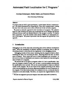
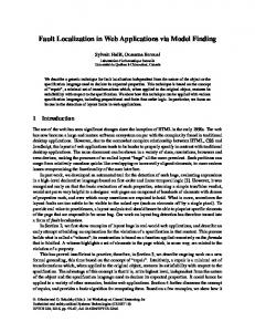
Our initial problem’s definition gives rise to a design whose structure is outlined in Figure 1. Although we know the intended behavior of the combinational logic block, we have to provide a running implementation for this block. As mentioned above, today this is done by using a hardware description language (HDLs). Figure 2 specifies the behavior of our solution in VHDL. Using this formal description we can do simulation, automatic verification, synthesis to a gate level representation and, as shown later on, we can also use the VHDL source code for fault localization. If we are interested in verreset clk
13 14 15 16 17 18 19 20 21 22 23 24 25 26 27 28 29 30
din
D − FF
y0
31 32 33 34 35 36 37 38
z2
D − FF combinational logic
y1
39 40 41 42
z1
D − FF y2
din CLK RESET
z0
y0 proc.
y1
process
sh.Reg
y2
comb
entity FSM is port ( reset : in clk : in d in : in z0 : out z1 : out z2 : out end FSM;
bit ; bit ; bit ; bit ; bit ; bit );
architecture BEHAV of FSM is signal y (3 downto 0) : bit vector ; begin comb: process ( y) variable a , b , c , d , h , g , e : bit ; begin b := y (1) nand y(2); c := y (1) nor y (2); a := not(y0 ) or c; d := b or c; h := a nand d; e := not(c ); g := y (0) nor e; z0