While existing solutions tackle aspects such as functionality and sequencing .... objectives (composite tasks) such that planning a wedding can be seen in terms.
Towards a Task-Oriented, Policy-Driven Business Requirements Specification for Web Services Stephen Gorton and Stephan Reiff-Marganiec Department of Computer Science University of Leicester University Road, Leicester LE1 7RH, UK {smg24, srm13 }@le.ac.uk
Abstract. Dynamic assembly of complex software is possible through automated composition of web services. Coordination scripts identify and orchestrate a number of services to fulfil a user or business goal. The automated process begins at the business requirement stage, thus there exists a need for expressing high level business requirements, in such a way that is accessible by businesses. Current solutions (such as BPMN and UML) fail to include specifications at the appropriate level of abstraction. Our approach defines a graphical notation to depict a business goal in terms of objectives, which are refined by tasks, where the specifics of each task as well as overarching business constraints are encapsulated in a descriptive way in policies.
1
Motivation
The advent of Service-oriented Architecture (SoA) makes software “on demand” a distinct possibility. The relatively recent introduction of web services means that automated composition of services can be achieved. Solutions already exist for service discovery and description, though these may be far from complete. Composition solutions also exist, with the Business Process Execution Language (BPEL1 ) the de facto standard. There is an obvious layer of abstraction required to bridge the gap between the business domain and the service domain. While attempts are often made at expressing business logic through composition or other technologies, there is a distinct lack of tools which can express precise requirements specifications at the business level. While existing solutions tackle aspects such as functionality and sequencing of business activities, none are complete to encompass all information required at the business level. Although bridges have been built between the service composition layer and the business requirements layer, they are not wide enough to accommodate the large requirements vehicle that must travel along it. 1
http://www-106.ibm.com/developerworks/webservices/library/ws-bpel/
The problem that we address in this paper regards business process modelling and analysis, and our goal is to develop a modelling language to accurately express a complete set of business requirements, through the use of policies, in terms of web service usage. One particular aspect is that the notation should be suitable for use by business users (not IT experts) and that it should be simple to use to encourage changes when demand arises. This work also includes discussion on further aspects such as workflows and SoA. We proceed in section 3 to give an overview of our approach. In section 4 we present the graphical notation used, followed by the description of additional considerations in section 5. We present an example of the graphical notation in section 6. Finally, we evaluate our approach in section 7 before drawing conclusions and describing further work in section 8.
2
Background
Service-oriented Architecture, and its implementation as Web Services, make the vision of just-in-time assembly of applications a distinct possibility. SoA refers to a system architecture where a number of independent services can be composed at runtime into larger applications in order to respond to immediate business needs or goals. Fundamentally this is based around a publish-find-bind paradigm. A service author writes a service and then publishes the same plus the interface description on the web. A service consumer can retrieve the description and if it describes a suitable service bind to the service at run-time. For details about SoA we would like to refer to Alonso et al. [1]. Of course there are some aspects that still must be addressed, most notably the automatic composition (i.e. identifying plans for composing services such that they fulfil some desirable goal) and, possibly more important, ways for end-users to express these goals (requirements) in the first place. In this paper we concentrate on the latter. End-user requirements are seen two-fold for the purpose of our work: one aspect is the flow of the business process, the other is the description of the business policies. Task flow is usually captured in a way that describes the operative nature of the business by using task maps or work flow languages. Task flow is obtained through business modelling as this requires a certain understanding of the business processes involved. Service description is provided by such standards as WSDL [4], while discovery is predominantly provided by UDDI [5]. Composition is offered in many ways, including the afore-mentioned BPEL. Abstract requirements specification, that is at the business level and has implementation-specific information removed (e.g. service details), has yet to find a suitable solution for SoA. We have reviewed current approaches to requirements specification, in terms of process management. In addition to approaches described here, more business process models are surveyed in [7].
2.1
Business Modelling
Business modelling refers to the specification of business processes and business logic such that the business level is addressed by business analysts, rather than software system analysts. In the world of web services, there are few options available for expressing these business requirements. Whilst composition technologies such as BPEL can express sequence logic in service usage, they do not do so at the more abstract business level. It could be stated that modelling notations for business processes occur in their 10000s, ranging from implementation level to the business level. The distance from implementation level reveals the amount of abstraction (i.e. the closer to the business level, the more abstraction is needed). In a recent white paper, Jasmine Noel notes that the future of enterprises is in BPM suites [15], therefore we consider the various BPM approaches as significant in this research. 2.2
Code-based Approach
Apart from natural English, structured languages are often used for expressing processes. In terms of WS, BPEL is identified as the most widely advertised process language, even though it was designed (from IBM’s WSFL [12] and Microsoft’s XLANG [22]) for service composition. Other solutions include WSCL [3] and WSCI [2]. Suites such as ebXML2 are also capable of expressing business processes. The main problem with these solutions is that they all represent implementation-level approaches to describing service interaction. While they perform their respective roles as required, they are not able to express high-level user requirements. They are suitable to model processes within which details about each involved service are already known. More traditional workflow languages are more appropriate for modelling processes. YAWL [24] is a workflow language that extends Petri nets to provide a powerful formal language with defined syntax and semantics. Further languages include SMAWL [21], GAT [14], XRL (initial blueprints in [11]) and WSFL. These solutions are considered better in terms of describing processes since they abstract away composition details that would be included in those solutions previously discussed. Although they describe processes, they are unable to define high-level requirements for activities or events that occur in the workflow. However, we note that any solution should include a suitable analysis of workflows and workflow patterns. 2.3
Process Calculi-based Approach
A sister approach to the code-based approaches, process calculi offer a formal method in which to express processes. Whilst not including enough information for actual composition, this approach allows one to model a (composition) process so that it can be verified and reasoned about. Semantics are required for 2
http://www.ebxml.org
this formality and process calculi such as Petri Nets (already used for YAWL), π-calculus and CCS all possess structured operational semantics. Examples of this approach are described in [10] and [8]. 2.4
Notation-based Approach
Graphical notations generally provide an intuitive method in which analysts can define processes by a sequence of activities or tasks. As with code-based approaches, there are a number of vendor-specific solutions, e.g. IBM’s WebSphere Business Modeller3 . However, they conveniently abstract away more implementation level details which make them more suitable for use in the business domain. Indeed, business analysts have long been using flow charts to organise processes, so a similar modelling notation that is adaptable to SoA is desirable. The most widely-accepted universal process notation for business processes is the Business Process Modelling Notation [17]. This notation is based around a Business Process Diagram (BPD). This diagram expresses simple flows, including operations on flows (e.g. split and merge), plus capabilities to handle exception flows. Processes in a BPD can be separated into swimlanes, therefore identifying different system viewpoints. Activities and other BPD objects may be given attributes to add more meaning. One particular advantage of BPMN is that it can be used to model a BPEL process [26]. However, it offers little to help locate services to match to each process activity. Even the specification suggests that strategy, data and information models and business rules are not a part of BPMN. In particular, we note that BPMN does not support the expression of non-functional business requirements (mapping directly to non-functional properties of services as analysed in [16] and formalised in [18]). Alternatively, another solution is to use the Activity Diagram component of the Unified Modelling Language (UML). These diagrams express the dynamic behaviour of systems in a clear and intuitive way. However, UML often suffers from a lack of clear semantics, though the syntax is clear. Further research goes into adding semantics for UML [27, 6]. Also, while the syntax of the diagram is intuitive, it is sometimes unclear as to what a particular layout would do. For example, in Fig. 1, it is unclear when D is executed. Does it occur after B and C, or once after either? This problem arises when B and C take different amounts of time to complete. Notations in general lack the ability of expressing any information that is not graphical, e.g. “this task should be completed in x time” or similar. Therefore we require a particular capability of expressing this further information, down to the sub-process (i.e. task or activity) level. 2.5
Business Policies
Business policies on the other hand express rules that are of a more generic nature; often they do not apply to a specific business process but rather to specific 3
http://www-306.ibm.com/software/integration/wbimodeler/
B D C
Fig. 1. UML fork and join example
tasks or the way that the business operates overall. Policies are descriptive in their nature. Policy description languages [13] have been used to express quality of service constraints or access control, that is to describe very low level properties of systems. The Appel policy language [20, 23] has been defined to express end-user rules in telecommunications systems and we are extending this in our ongoing work to interact with the task maps discussed in this paper. Our approach seeks to build on the conceptual ideas of BPMN by using a simpler graphical notation, but adding policies to express precise business requirements. In a similar way that a BPMN business process is broken down into events and activities in a BPD, our approach breaks down a business goal into several tasks that are arranged in a task map. Our notation can yield views in terms of control and data, though only control views are discussed in this paper.
3
Overview of Approach
The aims of our approach are two-fold: to allow businesses to easily express their required activities in the form of tasks, and to enable the specification of both core functionality and other non-functional requirements. This approach does not include enhancements to service composition approaches, which are out of the scope of this paper. Our approach is based on a business goal that is satisfied by a number of objectives, where each objective is fulfilled by a set of tasks performed in a defined order. This process is described using a simple graphical notation. Each task is automatically matched to a web service, thus tasks can be defined independent of prior service knowledge. Non-functional attributes, overarching business constraints and business rules are expressed as policies. 3.1
Process
Our graphical notation is intended to act as a modelling agent for businesses who choose to use web services. The process of requirements elicitation begins with
the specification of the business goal. This goal is broken down into objectives that are fulfilled by tasks, which represent atomic business activities. The goal is then expressed in terms of a task map and policies. Now there exists an accurate model for the business requirements. The task map (and policies) are read by a parsing engine (itself possibly a web service), which then searches Internet directories for web services that satisfy the requirements. Once all services have been located, their descriptions are returned. A coordination engine generates a coordination script according to the descriptions and flows in the task map. This script is then ready to be executed. 3.2
Goal Definition
To define the goal, the business must define the objectives that would satisfy it and the tasks required to satisfy each objective, along with the execution sequences of the tasks. A business goal is likely to be defined at a very high level and thus cannot be easily formalised. Suppose a couple wish to get married. Their overall goal is to plan their wedding. This cannot be easily formalised! Instead, they must break it down into objectives (composite tasks) such that planning a wedding can be seen in terms of planning the celebrations (stag and hen parties), planning the preparation (clothing, photography, etc.), planning the ceremony, planning the legal parts, planning the reception and planning the honeymoon. Each of these objectives can also be seen as too high-level to formalise. Therefore each is broken down further. This process continues until a set of atomic tasks has been reached, i.e. tasks that cannot be broken down further. Functionality is the core requirement for each task. Although functionality can be expressed at the composite task level, it can be more accurately expressed at the atomic task level. However, non-functional requirements may be expressed at the composite task level, such that they can propagate through to any subtask that does not overrule them. 3.3
Design
The foundation of our business model is the business goal, which is satisfied by a number of objectives. An objective obj is defined as a triple (T, m, K), where T is a set of all identified (atomic) tasks, m is a task map and K is a set of global or business constraints. These constraints have the ability to affect service composition or task execution, therefore incorporating ideas of aspectoriented computing. Informally, we identify all tasks that each represent a single business activity with their requirements, organise them according to execution sequence and subject the result to certain constraints. The task map m maps a set of control flows to a set of tasks. Thus it depicts process order of task execution. It is formally defined as a triple (O, C, D), where O is a set of operators, C is a set of control flows and D is a set of data flows. We might also refer to “sub” maps, which essentially are task maps, just that they
data in compensation
service
side effect (world change)
error data out
Fig. 2. Service as a computational entity.
form parts of other task maps. In order to easily define rules for our operators, we define a set of entities E, the set of all tasks and operators given by E = T ∪ O. An operator op ∈ O is a function on a control flow, with the ability to split and merge the flow as defined in section 4.3. A control flow is an execution sequence of entities and a data flow is a route of data between tasks. Entities also are ordered in the task map showing their relative execution order. 3.4
Policies
Rich, high-level business requirements will include more than simple processoriented core functionality. To fully express what a business wants, the ability to specify non-functional requirements (e.g. resource constraints) is required. Further generic rules describing the operation of the business as well as the constraints that apply to certain tasks must be expressed. Our approach uses policies to encode this information. We have identified in previous work [19] 4 types of policies: conditional ECAs (Event-Condition-Action), unconditional ECAs (i.e. ECAs with true as condition), conditional goals and unconditional goals (i.e. just actions). Goals are distinct from ECAs in that they do not have a triggering event. A policy is triggered when the triggering event occurs: e.g. the flow has reached a certain state or a certain action is produced (e.g. an order is being sent out). For example, a task may be specified such that it allows for up to 4 inputs, but a policy might define that at least 2 must exist for proceeding. This might be the case if the inputs were quotes for products, and the business only allows a decision once a certain number of quotes has been obtained. A condition states what variant must be true in order for an action to take place. This concept allows for testing on inputs and environment variables. It also allows for the expression of non-functional attributes such as financial cost, temporal and spatial availabilities. The actions specify what the task should do and thus express core functional requirements. In addition, an action should be included for error flows should there be any runtime process problem. 3.5
Services
A service is a computational entity that maps input data to output data, respects certain non-functional properties, might change a world condition and has a compensation action (e.g. undo as in [9]). In Fig. 2, we see how a service is
control
ext in
data data
task compensate
service error
control
data
error side effect
data
Fig. 3. Services map directly to tasks.
graphically represented, and in Fig. 3 how a service maps to a task (or composite task). Note that the service may be of a composite nature (i.e. composed of other services). In effect, we expect that a (composite) service can map directly to a (composite) task. Should there be no service available, the error output flow is instantiated. However, the mapping of tasks to services is included here for completeness: the business user is not required to be aware of this detail, as they work at the more abstract task and policies level.
4
Graphical Modelling Constructs
We now present the graphical notation used in our modelling language, along with more formal definitions of each language component. 4.1
Task
A task is a business activity that contributes to an objective and thus the wider business goal. Each task t ∈ T (the set of all tasks) is a quadruple (i, R, P, X), where i is a unique identifier and: – A requirement r ∈ R is defined as either a functional (F ) or non-functional (N ) requirement. The set of requirements satisfies the following: R = F ∪ N , F ∩ N = ∅ and F 6= ∅. Informally we say that a requirement is either exclusively functional or non-functional, and the set must include at least one functional requirement. – The set of problem instructions P ⊆ SP ×T I, where SP are source problems and T I are instructions on actions to perform (e.g. if some source problem spx ∈ SP occurred, then instruction tix ∈ T I would be performed). control
ext in
data
task
control
data
Fig. 4. A task with its input/output flows
– The set X of external inputs represents a policy that affects this particular task. This is in addition to the standard task requirements. For example, a company director may place extra constraints on a particular business activity after it has been designed by a project team. Finally, we note that tasks have inputs and outputs. Each task must have a control input and a control output. Once control has reached a task’s input, the task’s triggers are activated. On completion of the task, the control leaves through its output channel. control
ext in
data
task
control
data
Fig. 5. Composite tasks are expressed similarly to atomic tasks
Composite Task. Composite tasks are task sub-maps, enabling the designers to separate concerns over aspects of the business goal. Just as with an atomic task, the composite task has control and data inputs and outputs, along with external policy inputs. The control and data inputs map to the starting task(s) inside the sub-map, the outputs similarly are from the final tasks and the external policy inputs affect each task in the sub-map. 4.2
Flows
A flow is a sequence of entities (tasks or operators) in the task map. A route is a flow that begins at the start of the map and finishes at the end. A flow can either be a control flow or a data flow. Each task must be connected to the task map by a control flow, i.e. it must be in a route. Otherwise, the task is redundant as there is no way to invoke it. All tasks inside a task map are subject to policies that are centrally specified by the consuming business or governing law. For example, country X may have a law stating that no business in X may use a service (software or non-software) from another country Y. Alternatively, a corporate policy may state that the use of a direct competitor’s services is forbidden. These examples limit the user of services that are available to conduct the task; other policies might change the shape of the task map. An example of the latter is a policy that requires the obtaining of at least 3 quotes before a purchase can be made. We recognise that whilst control flow is important to the precise execution of a set of tasks, the data flow may not be an exact mirror. Indeed partial data flows may also exist. For example, where a control flow is t1 → t2 → t3 , data output from t1 may not be required at t2 but instead at t3 , thus the data flow is t1 → t3 .
t1
t2
t3
Fig. 6. Data flows are not necessarily the same as control flows.
4.3
Operators
In addition to tasks and flows, which can express simple sequencing, we define operators that are functions on control flows. These further enable a business to accurately model their business goal. The operators are described here with respect to control flows, rather than data flows. fx
fx.1
fx.2
fx.3
fx.4
fx.5
Fig. 7. The flow split operator distributes control from one flow to many.
Flow Split. The flow split operator is an n-ary function F S : in → OU T , where in is a control flow input and OU T is a set of control flow outputs. In Fig. 7, the operator is pictured with one input and four output flows. When the active control flow reaches the operator, control is distributed amongst the outgoing flows such that each flow progresses simultaneously. For example, in a typical customer-supplier-warehouse example, a product dispatch may involve simultaneously notifying the customer of the dispatch whilst ordering a stock replacement. Both tasks here may be done independently. fx.1
fx.2
fx.3
fx.4
n
fx
Fig. 8. In conditional merging, n control flows can combine to one according to business decisions over each flow.
Conditional Merge. The conditional merge operator takes a set of active input control flows and, subject to business-defined constraints, merges them with synchronisation to a single output flow. It is a function CM : IN → out. The component IN is a set of pairs (c, b) where c ∈ C (control flows) and b ∈ B. The component b specifies whether or not this particular flow must reach the operator before the flow is allowed to proceed. Those flows with true values are called mandatory flows, while those with f alse values are optional flows. These are graphically described as having either filled or empty circles, respectively, at the intersection of the flow and the operator. The component out defines an output flow and n specifies the number of flows that must reach the operator before proceeding, where 1 ≤ n ≤ |IN |. Graphically, n is written inside the operator’s diamond this is shown as value i). Since the operator can also refer to mandatory flows, we also have that n must be greater than or equal to the number of mandatory participant flows. Partial synchronisation is therefore introduced here, with cancellation of optional flows addressed in section 5.1. For example, when looking for airline ticket quotes, one might request quotes from three suppliers, including the preferred supplier. Before booking, we might say that we must have a quote from the preferred supplier, plus one more. Thus there is one mandatory flow and a minimum of two flows to complete before proceeding. fx test
fx.1
fx.2
Fig. 9. Control flow Junction. Depending on the result of some test, the control flow may choose which route to take.
Flow Junction. A flow junction operator diverts the control flow down one of two possible output routes according to a binary test. The function is written as: ( out1 if test = true, F J : in × test = out2 if test = f alse. In the description (in, out1 , out2 , test), the element test is a binary test such that when resolved, if true control diverts to the primary output and secondary otherwise. Strict Preference. A strict preference operator attempts to execute a series of tasks in a defined order, progressing when one of the tasks is completed. The
p1
tp.1
tp.2
tp.3 error
Fig. 10. Strict Preference allows a business to specify their priorities over tasks.
function is written SP : in → out, where out is one of a set of possible output flows. We describe strict preference as a set P T ∪ {error}. P T is an ordered set of pairs in the form (t, n), where t ∈ T represents a task and n ∈ N is a unique priority in the range 1 ≤ n ≤ |P T |, such that the task with highest priority is attempted first. In the case where no task can be completed (due to a timeout or other issue), the error output flow is selected. Each task in the operator specifies its own output flow which is followed when its parent task is completed. Thus after the operator, there is one active output flow plus a number of inactive flows.
tc.1
tc.2
c1
tc.3
error
Fig. 11. Random Choice enables random selection of a task to be invoked.
Random Choice. Choice is similar to preference, but without priorities attached to included tasks. It is described simply as CT ⊆ T . When control reaches this operator, all tasks may be attempted simultaneously. When a first task reaches a commit stage, then all others are cancelled (see section 5.1). The output control flow connected with this task is then proceeded along. Graphically, the difference with the preference operator is that all included tasks are lined up on the same plane. fx.1
fx.2
fx.3
fx.4
fx.5
fx
Fig. 12. Four incoming control flows merge into one.
Flow Merge. Flow merge is a unary operator in that it takes a set of control flow inputs IN which maps to a single output flow out in the form F M : IN → out, where IN is a non-empty set of control flows such that |IN | ≥ 2. In order to preserve synchronisation, we say that only one flow of the incoming set must be active, with all others inactive. This may be the result of a prior junction, preference or choice operator. If more than one flow is active, then the conditional merge operator must be used.
5 5.1
Further Considerations Cancellation of Tasks
In the case of the random choice and conditional merge operators, there is the likelihood that partial synchronisation will leave previous tasks in a state of execution. Thus there is a need for some cancellation function, in order to avoid unwanted side-effects caused by the cancelled tasks (e.g. a penalty for cancelled airline ticket booking). We observe that there are essentially two types of task. The first is statedependent, meaning that the overall system state is changed during the execution of the task. The second is state-independent, which possibly changes the system state after its execution. In the latter case, we say that the task is made up of a pre-computation stage followed by a commit stage. A delay is possible between stages and cancellation is only available before the commit. In the former situation, there are an arbitrary number of state changes possible, therefore there exists an arbitrary number of pre-computation stages, each followed by a commit. In this situation, a cancellation of the task is only available before the first commit. However we do recognise the possibility of quasi-atomicity; made possible through the introduction of history buffers. This idea has been initially addressed in [9]. However this aspect is out of the scope of this paper. 5.2
Workflows
An initial analysis indicates that our notation supports many of the workflows described in [25]. However, the following are not supported and subject to further investigation: – Implicit termination; – Merging without synchronisation; – Multiple instance patterns. At present, we believe that the although the implicit termination workflow may be useful and easily introduced to our notation, the other patterns are not desirable in that they can cause unexpected and over-complicated behaviour from the designer’s point of view. In addition, the following patterns are indirectly implemented:
– Arbitrary cycles We propose that bounded cycles be allowed in the task map, though this is subject to further consideration. – Deferred choice The choice over which output path to take may be dependent on an environmental variable, rather than a corporate variable as defined by the business. – Interleaved parallel routing The organisation of tasks in the task map expresses the order in which tasks are executed. Noting a flowchart “begin at the top” approach, tasks are invoked in the order specified by the control flows with respect to the layout. – Milestone If the milestone is a check to see if something in the system is true, we can model this using a global variable that can be checked by any task (with policies). – Cancel activity / case This workflow is implicitly addressed in terms of cancellation procedures briefly described in section 5.1. 5.3
Negotiation
There is a significant possibility that situations will arise where multiple data sources will not effectively work together to perform a task. When choosing a holiday destination and a budget, a chosen destination of the Seychelles and a budget of £10 (from the UK) will obviously not yield any useful result when attempting to make a booking. Thus there needs to be some element of negotiation. We note that data accordance is different to compatibility issues, which we regard as problems in task execution. To facilitate negotiation, we initially propose that task policies state priorities on requirements. These priority values should include: “must”, “must not”, “should”, “should not”, “prefer” and “prefer not”. A suitable strategy then needs to be devised for resolving a possible negotiation process.
6
Wedding Example
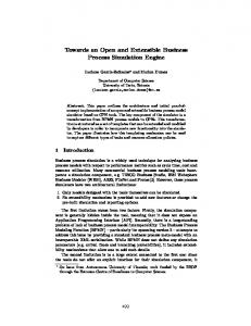
Anyone who has been married will probably realise that there is much to plan for the event. Planning often begins months, even years, before the actual day, and costs are often above £10k. The wedding example is suitable as a simple demonstration of our notation. The overall business goal is to plan the wedding, and this can be broken down into the categories: pre-wedding day celebrations, pre-wedding preparations, ceremony, legalities, reception and honeymoon. Each of these categories can be represented as composite tasks, with their own independent task maps, although there is still a “master map” that specifies the execution sequence of each composite task (e.g. typically the ceremony and reception venues would need to be booked first and at the same time, whilst the celebratory stag and hen nights are the last to be organised).
start
t1: jobs allocated to either husband or wife
6.1
t1
Honeymoon Booking Sub-Example
t2: wife chooses destination
t2
both flows must reach here before proceeding
2
t4: best destination and budget decided
t5
t4
t6
At least two quotes must be received, including the preferred agency, before proceeding
t7
t5, t6 , t7: quotes are obtained from three travel agencies simultaneously
2
t8: quotes are ordered into preference
t8
p1:an attempt to book the best offer is made, with the second offer attempted if the first failed
t3: husband chooses budget
t3
p1
t9 t10
t11
t12
c1
c1: currency is changed at either one of two banks, with no preference between either
end
Fig. 13. The simplified honeymoon example
The wedding example is a particularly large goal to express, so we look at one of the objectives, that of planning the honeymoon (pictured in Fig. 13). This is mostly the same as booking a holiday. Our example is a “modern” version in that both prospective husband and wife get to organise the honeymoon together. After a preliminary task of job allocation, the first tasks are to decide where to go (t2 ) and how much to spend (t3 ). The wife has the privilege of the former
choice while the husband has the more difficult latter task; both may be done in parallel. Once both decisions have been made (negotiation may be required!), the couple then proceed to look for three travel agencies from whom they wish to obtain quotes (t4 ). The agencies are contacted simultaneously (t5 , t6 and t7 ), and on receipt of at least two replies, including one from their favoured agency, the couple then decide which order of preference, i.e. primary and secondary, they rate the quotes (t8 ). An attempt is then made at booking the primary quote (t9 ), with the secondary as backup in the event of a failure occurring in the primary booking (t10 ). Once complete, the final task is to exchange currency at one of two banks (t11 and t12 ). Since both banks offer the same rate of exchange, the couple have no preference over which to use. From this example, we can extract specific control flows as follows: – – – –
start → t1 start → t1 start → t1 start → t1
→ [t2 |t3 ] → t4 → [t2 |t3 ] → t4 → [t2 |t3 ] → t4 → [t2 |t3 ] → t4
→ [t5 |t6 |t7 ] → t8 → [t5 |t6 |t7 ] → t8 → [t5 |t6 |t7 ] → t8 → [t5 |t6 |t7 ] → t8
→ t9 → t11 → end. → t10 → t11 → end. → t9 → t12 → end. → t10 → t12 → end.
We note that parallel flows exist, written [a|b|c] where a, b and c are individual entity flows. By identifying flows in this way, it is possible to transform the diagram into some workflow or process algebra language, making it suitable for verification, e.g. with model checking. The possibility also arises for dynamic composition scripts.
7
Evaluation
Our approach has been to simplify the the requirements specification process for non-IT experts working in the business domain. Despite the existence of other methods, we believe that our method has the following advantages when applied at the business level: – Expressiveness Our language is able to express as many or as few requirements as is deemed necessary by the business. Task maps are an easy method to understand and, with the aid of a wizard, policies are easy to construct. Despite being at a higher level of abstraction, the task map can be automatically mapped into service coordination scripts. We also include operators in our notation that are non-existent in current notations, e.g. preference, thus increasing the expressiveness for end users. – No Binding All tasks are expressed without the knowledge of services that are available. The job of matching services to tasks is performed automatically by a search engine, based on ontologies and richer semantic descriptions of web services,
which is out of the scope of this paper (there is active research in this area which has led to some preliminary results; most ideas are centred around planning algorithms). – Change If some aspect of the business goal needs changing to cater for a new or changed business requirement, it can be done with relative ease by altering the task map or underlying policies. The service coordination script is generated automatically, which is subject to any changes made to the specification. – Technology Compatibility Though not an immediate aspect of business versatility, our solution is able to take advantage of current solutions that exist, e.g. BPEL as the coordination script. In this respect, a business always has the option of altering their executable coordination script before proceeding. – Composition Views We add that our solution can generate different views that are customized to different stakeholders. In particular, a project manager may be more interested in (composite) task requirements whereas the IT director may be more interested in the global or business-wide constraints. Further low level views include control flow views and data flow views. – Workflows Our notation is able to support many of the workflow patterns as described in [25]. For a further discussion, see section 5.2.
8
Conclusions and Further Work
We have presented a notation for describing business requirements at an abstract level. A business goal is defined in terms of objectives which are further refined by tasks. Tasks are organised into a task map. Policies define complete requirements and specifications for tasks, and are more generic in that they can be used throughout the task map, providing information to many parts of a business goal, and even across multiple goals. We firmly believe that this solution is able to fill the gap between service levels and business levels. Our further work includes refinement of the ideas presented on policies, as briefly described in section 3.4. A possible implementation of these may be the APPEL policy language [23], which was developed with respect to telephony systems. Formal semantics need to be applied to the model, including transformations to other notations such as service coordination, configuration and choreography. Finally, we propose that a workbench be designed to enable designing of task maps and policies through the use of a graphical user interface.
Acknowledgements This work is funded by the IST-FET IST-2005-16004 project SENSORIA (Software Engineering for Service-Oriented Overlay Computers). Further thanks to Marie-Claude Gaudel for her advice on cancellation and undoing.
References 1. G. Alonso, F. Casati, H. Kuno, and V. Machiraiu. Web Services: Concepts, Architectures and Applications. Springer, 2004. 2. A. Arkin, S. Askary, S. Fordin, W. Jekeli, K. Kawaguchi, D. Orchard, S. Pogliani, K. Riemer, S. Struble, P. Takacsi-Nagy, I. Trickovic, and S. Zimek. Web services choreography interface (wsci). W3C, Aug 2002. http://www.w3.org/TR/wsci/. 3. A. Banerji, C. Bartolini, D. Beringer, V. Chopella, K. Govindarajan, A. Karp, H. Kuno, M. Lemon, G. Pogossiants, S. Sharma, and S. Williams. Web services conversation language (wscl). W3C, Mar 2002. http://www.w3.org/TR/wscl10/. 4. E. Christensen, F. Curbera, G. Meredith, and S. Weerawarana. Web services description language (wsdl). W3C, Mar 2001. http://www.w3.org/TR/wsdl/. 5. L. Clement, A. Hately, C. von Riegen, T. Rogers, T. Bellwood, S. Capell, J. Colgrave, M. Dovey, D. Feygin, R. Kochman, P. Macias, M. Novotny, M. Paolucci, K. Sycara, P. Wenzel, and Z. Wu. Uddi version 3.0.2. OASIS, Oct 2004. http://uddi.org/pubs/uddi-v3.0.2-20041019.pdf. 6. H. Eshuis. Semantics and verification of UML Activity Diagrams for workflow modelling, 2002. 7. Peter Fettke, Peter Loos, and J¨ org Zwicker. Business process reference models: Survey and classification. In Christoph Bussler and Armin Haller, editors, Business Process Management Workshops, volume 3812, pages 469–483, 2005. 8. Xiang Fu, Tevfik Bultan, and Jianwen Su. Formal verification of e-services and workflows. In Christoph Bussler, Richard Hull, Sheila A. McIlraith, Maria E. Orlowska, Barbara Pernici, and Jian Yang, editors, WES, volume 2512 of Lecture Notes in Computer Science, pages 188–202. Springer, 2002. 9. M-C. Gaudel. Toward undoing in composite web services. LRI, Paris-Sud University and CNRS, Orsay, France, 2004. 10. Rachid Hamadi and Boualem Benatallah. A petri net-based model for web service composition. In Klaus-Dieter Schewe and Xiaofang Zhou, editors, ADC, volume 17 of CRPIT, pages 191–200. Australian Computer Society, 2003. 11. Akhil Kumar and J. Leon Zhao. Workflow support for electronic commerce applications. Decision Support Systems, 32(3):265–278, 2002. 12. F. Leymann. Web service flow language. Technical report, IBM Software Group, 2001. http://www-306.ibm.com/software/solutions/webservices/pdf/WSFL.pdf. 13. E. Lupu and M. Sloman. Conflicts in policy-based distributed systems management. IEEE Trans. Software Eng., 25(6):852–869, 1999. 14. S. Nepal, A. Fekete, P. Greenfield, J. Jang, D. Kuo, and T. Shi. A service-oriented workflow language for robust interacting applications. In Robert Meersman, Zahir ¨ Tari, Mohand-Said Hacid, John Mylopoulos, Barbara Pernici, Ozalp Babaoglu, Hans-Arno Jacobsen, Joseph P. Loyall, Michael Kifer, and Stefano Spaccapietra, editors, OTM Conferences (1), volume 3760 of Lecture Notes in Computer Science, pages 40–58. Springer, 2005.
15. J. Noel. Bpm and soa: Better together. IBM White Paper, IBM Corporation, 2005. http://www.findwhitepapers.com/docs/vendors/IBM/BPM%20SOA%20BetterTogether%20%20Offer.pdf. 16. P. Oaks, A. H. M. ter Hofstede, and D. Edmond. Capabilities: Describing what services can do. In M. E. Orlowska, S. Weerawarana, M. P. Papazoglou, and J. Yang, editors, ICSOC, volume 2910 of Lecture Notes in Computer Science, pages 1–16. Springer, 2003. 17. Object Management Group (OMG). Business Process Modeling Notation (BPMN) Specification, Feb 2006. 18. J. O’Sullivan, D. Edmond, and A. H. M. ter Hofstede. Formal description of non-functional service properties. Technical Report FIT-TR-2005-01, Queensland University of Technology, Brisbane, Feb 2005. 19. S. Reiff-Marganiec and K. J. Turner. Feature interaction in policies. Computer Networks, 45(5):569–584, 2004. 20. S. Reiff-Marganiec, K. J. Turner, and L. Blair. Appel: The accent policy environment/language. Technical Report CSM-164, University of Stirling, Jun 2005. 21. C. Stefansen. Smawl: A small workflow language based on ccs. In O. Belo, J. Eder, J. Falc˜ ao e Cunha, and O. Pastor, editors, CAiSE Short Paper Proceedings, volume 161 of CEUR Workshop Proceedings. CEUR-WS.org, 2005. 22. S. Thatte. Xlang. Microsoft Corporation. http://www.gotdotnet.com/team/xml wsspecs/xlang-c/default.htm. 23. K. J. Turner, S. Reiff-Marganiec, L. Blair, J. Pang, T. Gray, P. Perry, and J. Ireland. Policy support for call control. Computer Standards and Interfaces, August 2005. 24. W. M. P. van der Aalst and A. H. M. ter Hofstede. Yawl: yet another workflow language. Inf. Syst., 30(4):245–275, 2005. 25. W. M. P van der Aalst, A. H. M. ter Hofstede, B. Kiepuszewski, and A. P. Barros. Workflow patterns. Technical Report FIT-TR-2002-03, Queensland University of Technology, Brisbane, 2002. 26. S. A. White. Using bpmn to model a bpel process. BPTrends, 2005. http://www.bptrends.com, accessed on 15/03/06. 27. Dong Yang and Shen sheng Zhang. Using π-calculus to formalize UML activity diagram. In ECBS, pages 47–54. IEEE Computer Society, 2003.