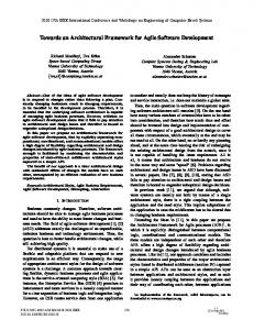
Towards an Architectural Design Framework for Automotive Systems Development Hugo G. Chalé Góngora1, Thierry Gaudré2, Sara Tucci-Piergiovanni3
Abstract. This paper discusses the concepts of Model-Based Systems Engineering (MBSE) and of Architecture Frameworks (AF) and presents some preliminary results of current initiatives at Renault on these subjects. We advocate the adoption of a MBSE approach, i.e., the application of modeling to support a SE methodology covering the SE design process and activities and supporting the methods that are needed to carry out these activities. This results in the definition of an architectural design framework for the automotive systems development currently implemented in a SysML specialization. It is expected that this work will contribute to foster the reflection on an architecture framework for the automotive industry and stimulate discussions across the automotive community. Keywords: complex systems, architecture framework, SysML, Model-Based Systems Engineering.
1 Introduction Commercial automobiles have turned into very complex high-technology products in a relatively short time span. Different factors contribute to this complexity. One of them is the increasing number of vehicle functionalities supported by software, electronics and mechatronic technologies, a trend that does not seem to slow down. The involvement of carmakers in the development of these functionalities differs from one vehicle domain to the other (chassis, body, powertrain), ranging from black box integration to white-box developments. Another factor is the way in which car manufacturers have evolved from their historical mechanical and manufacturing background to the intricate organizations that develop the automobile products of today. Generally, this evolution has translated into development processes that are not as efficient, flexible and agile as they could or should be. Modern vehicle systems impose indeed a cultural and organizational change from carmakers, in that their development calls for the participation of many different professional fields each having its own language, its own jargon. Besides this multi-disciplinary aspect, vehicle systems are very often developed in a concurrent 1
RENAULT, 1 avenue du Golf, 78288 Guyancourt, France,
[email protected] RENAULT, 1 avenue du Golf, 78288 Guyancourt, France,
[email protected] 3 CEA, LIST, Laboratory of model-driven engineering for embedded systems, PC 174, 91191 Gif-sur-Yvette, France,
[email protected] 2
2
engineering approach, instead of a linear or cascade process. The advent of the electrical vehicle makes this last two factors even more evident, not only because of the “untraditional” technologies that carmakers need to master but also, and specially, because the arrival of new stakeholders, actors and interests around the electrical vehicle mean that the traditional scope of the automobile has changed. The need to master these different complexity-inducing factors and improve the efficiency of product development, plus the arrival of the ISO 26262 standard (which besides from safety-related aspects, also raises issues concerning development processes of automotive systems, currently under-formalized) have motivated Renault to deploy Systems Engineering. The first visible results of this deployment were some evolutions of Renault’s engineering divisions: first, a list of vehicle systems covering main classical functionalities (e.g. braking, airconditioning) was built, to improve requirements consistency between the whole vehicle and its elementary parts. Second, it was decided to deploy a standard SE process on certain vehicle systems based on their complexity or innovative character. This process is in line with INCOSE references and adapted to specificities of automotive systems, for instance the management of re-usable system references (Chalé Góngora et al. 2010). As a result, a shared SE data model and process, and standard document templates, were elaborated. The SE process at Renault has mainly been (and still is) a document-centric one depending largely on testing and prototyping performed at component or specialty domain levels. The authoring of the different objects of the process (e.g. use-cases, requirements, and architectures) is somewhat troublesome and time-consuming. One of the reasons for this is that these objects are elaborated by means of manual transformations of ad-hoc data and information contained in different documents that are transmitted from one activity of the process to the other and from one engineering domain to the other. Another reason is that the methods for elaborating the objects are applied (and to a certain degree described) inconsistently. Still, in order to avoid creating another complexity-inducing factor, all the objects of the systems design process should be described as clearly as possible. A better formalization of processes and of the process objects should certainly contribute to avoid confusion and misinterpretations in the development of systems. This is further stressed by the fact that Renault, like all other car manufacturers, relies heavily on third parties to develop vehicle systems. One of the main drawbacks in implementing the SE process can then be summarized as a lack of semantic consistency among the different objects and activities of the process and a lack of integration and alignment of both activities and engineering disciplines. While there might not be one single solution to all these problems, we believe that the use of formal and informal (but consistent) models that comply with a common semantic model could facilitate systems engineering activities and avoid the encountered drawbacks of document-centric, error-prone implementations of the process. Our current improvement initiatives are divided into two main activities: The definition of common unambiguous semantics through the formalization of SE terminology in a formal ontology, as presented in
3
(Chalé Góngora et al. 2010 and 2011); and a computer-assisted SE process that formalizes and partially automates the system design activities. This paper presents preliminary results of the latter initiative. The initiative advocates the adoption of a Model-Based Systems Engineering (MBSE) approach, i.e., the application of modeling for the support of SE activities. The envisaged modeling approach has the following features: 1)It complies with architecture frameworks principles. Following these principles, the model of the system is defined and analyzed at different levels of abstraction and from different viewpoints. At each level, the system model is described by a set of views (typically, graphical representations). A view describes the architecture of the system at some level of abstraction and in conformance to a viewpoint. Interestingly, relationships between (i) elements at different level of abstractions and/or (ii) belonging to different viewpoints are explicitly traced by well-defined refinement/decomposition methods. The paper presents how SE activities are formalized through the definition of an architectural design framework and related models. 2) It uses standard models for architectural framework description. In order to build standard models, a standard architecture modeling language is needed. Such a language must support (i) system architecture structuring and decomposition, (ii) abstraction and refinement, (iii) system viewpoints definition, and (iv) traceability between elements of the model. Today, the SysML language (SysML 2010) represents a good and usable choice, being a widely accepted standard for system modeling, especially in industry domains. The paper presents the use and specialization of SysML for the description of the proposed architectural design framework. The paper is organized as follows: Section 2 discusses concepts of MBSE and of Architecture Frameworks (AF), detailing objectives and motivations of our approach. Section 3 briefly presents the systems design process and outlines the proposed architectural design framework. Section 4 presents the SysML diagrams that implement the different views of the architectural design framework, along with the data model based on a SysML specialization. The paper concludes with a presentation of possible extensions of the proposed architectural design framework to tend toward the definition of a true and complete architecture framework for the automotive industry.
2 Towards MBSE Systems Engineering (SE) proposes a holistic approach and a set of principles and methods for successfully engineering systems that meet stakeholder needs and maximize the value delivered to stakeholders. MBSE, on the other hand, aims at producing a consistent system model that contains all the information that is required to completely describe, verify and validate the system. The benefits of implementing MBSE include an improvement of quality, through a more rigorous and costless traceability between requirements, design, analysis and testing; an in-
4
crease in productivity, through the reuse of models and automated document generation (Estefan 2008 and Friedenthal et al. 2008); and an improvement in communication, by integrating views of the system from multiple perspectives (Wand and Dagli 2011). At the heart of MBSE, lies the concept of architecture, which can be defined according to ANSI/IEEE Std 1471-2000 (IEEE 2000) as “the fundamental organization of a system embodied in its elements, their relationship to each other and to the environment, and the principles governing its design and evolution”. Therefore, according to the principles of SE, wherever there is a need there should be an architecture and wherever there is an architecture there should be a need (Watkins and Dagli 2010). Furthermore, the results presented in (Elm 2011) and (Hounour 2010 and 2011) show a strong relationship between project performance and product architecture and trade study capabilities, on one hand, and between project success and the relative weight of these same activities with respect to the overall cost of the project, on the other hand. Not surprisingly, in many industrial domains, the set up of system architecture design activities and the use of AF has proven particularly beneficial for the management of large complex system projects involving different organizations (Broy 2009). An AF can be defined as a standard set of elements that enables and facilitates the description of architectures in a complete, consistent, homogeneous and unambiguous way and provides guidance on how to create such description. An AF helps to understand the way in which a specific domain develops products or services. Some well known examples of architecture frameworks are DoDAF, MoDAF and TOGAF. These examples provide concepts, guidelines, best practices, and methods that are tailored for the needs of specific domains, respectively, defense and information technologies. They apply similar principles to organize and structure information using different levels of abstraction. In the automotive industry, a standard AF does not exist yet, although this concept and its potential benefits have been discussed before, like in (Broy 2009). The work presented in this paper is intended to provide the Systems Engineering groundwork for starting the construction of an architecture framework for the automotive industry, by defining an architectural design framework which only supports the system design process, i.e. the main “Technical processes” defined by the ISO/IEC 15288 standard. In the future, the Renault intends to define and share with other automotive actors a true and complete AF for the automotive domain, which will provide, in its final version, an overarching set of concepts, guidance, best practices, and methods that will support all the processes defined by ISO/IEC 15288 standard (Enterprise, Agreement, Project and Technical processes). The purpose of the AF is to ensure that system architectures can be understood, shared, analyzed and compared across organizational and project boundaries, in order to help decision makers to make key decisions more effectively thanks to structured, organized information sharing. This shall enhance the efficiency of the value creation stream and facilitate the integration of innovations into the vehicle and the reduction of risks. The proposed AF for automotive systems and the systems design process that it supports are described in the following paragraphs.
5
3 The Starting Point The Systems Design Process. When defining the systems design process, we tried to answer to a simple question: how do we design our systems? Or, rather, how would we like to design our systems? The logical answer to this question was that we should strictly follow Systems Engineering principles (of course). So, not surprisingly, the four main activities of the systems design process are the Elicitation of Stakeholders Requirements, the Elaboration of System Technical Requirements, the Functional Architecture Design and the Organic Architecture Design. During the “Elicitation of stakeholders requirements” activity, we identify the scope, the environment and the main actors concerned in the development of the system (the system of interest). The original stakeholders needs are captured, analyzed (according to each operational context of the system’s lifecycle) and generally structured using a use-case approach. These use-cases are refined in their turn by operational scenarios. The outcome of this activity is a set of (individually) clear stakeholder requirements, including the purpose, missions, objectives and scope of the system, as well as other technical measures of the “success” of the system. The goal of the “Elaboration of the system technical requirements” activity, is to transform the stakeholder requirements into a set of precise, achievable and consistent requirements, with tradeoffs between inconsistent or contradictory stakeholder requirements being possible. System technical requirements are organized and classified according to their type (behavioral, functional, performance, RAMS, operational, design, withdrawal, recycling). The objectives of “Functional architecture design” activity are, on one hand, to identify, describe and make more precise (by decomposing them) the functions or transformations that the system must perform in order to satisfy the requirements (mainly functional requirements). And, on the other hand, to specify the flows (i.e., information, energy or material flows) that are produced or consumed by the functions. The internal dynamic behavior of the system is also an outcome of this activity and corresponds to the logic scheduling of the execution of the system functions. The outcome of the “Organic architecture design” activity is the definition of the components of the system, of their interfaces and of their connections. The system architecture shall fully satisfy the system technical requirements, including non-functional requirements (like cost, weight and size of the system, kind of interfaces, forbidden or authorized use of materials, etc.), and other technical measures or criteria (measures of effectiveness, key performance parameters, etc.). During this activity, the system functions, defined in the previous activity, are allocated to the constituents of the system and, eventually, decomposed again to achieve an optimal allocation. The flows produced and consumed by the allocated functions are associated to the interfaces and connectors that shall transport them. New interfaces can be defined, depending on architectural choices that are made.
6
“Dependability” and the “Evaluation and Optimization” activities take place during all the systems design process. It is not the aim this paper to deal with these activities. For more information about the Dependability analysis activity, the reader can refer to (Chalé Góngora et al 2010 and 2011), where we focus on the safety aspects of dependability as the main objective is to comply with the ISO 26262 standard. The “Evaluation and Optimization” activity is presented in (Doufene et al. 2012). Similarly, all the activities of the systems design process are the object of “Verification and Validation” activities, such as inspections (of documents, models or plans), simulation, model checking, design reviews, etc. The systems design process is recursive and iterative, with several design loops that can be repeated partially or completely following the evolution of needs or the emergence of bottom-up constraints, like the impossibility to realize certain components of the system. At the end of (one loop) of the process , sub-systems are developed following either a similar process, if the sub-system is complex in the sense that it calls for different professional fields (disciplines or technologies), or a domain-specific process, if the subsystem calls for only one professional field such as software, electronics, mechanics, etc. The architectural design framework presented below provides the methods and views (or sets of models) that completely support the systems design process presented here. Background of the architectural design framework. The background of the architectural design framework presented in this paper can be found in the work of (Krob 2009 and 2010) concerning the architecture of complex systems. This work presents an architecture framework derived from the SAGACE method (Penalva 1997), which is structured on three main pillars: a modeling methodology; a graphical representation based on a nine-viewpoint matrix, or analysis grid, consisting of three main viewpoints (operational, functional and structural or constructional), each refined by three temporal perspectives; and a graphical modeling language. When adapting this framework to the systems design process described above, we used the same main viewpoints to support the activities of the process and we added a requirements viewpoint for consistency purposes. The Operational, Requirements, Functional and Constructional Viewpoints respectively support the Elicitation of stakeholder requirements, the Elaboration of system technical requirements and the Functional and Organic architecture design activities. Figure 1 presents an overview of viewpoints of the proposed architectural design framework. Abstraction
Requirements Viewpoint
Operational Viewpoint
Functional Viewpoint
Constructional Viewpoint
Figure 1. Viewpoints of the architectural design framework
7
More precisely, each activity of the systems design process calls for specific design and analysis methods, as proposed in (Krob 2009 and 2010). These methods are supported by one or more views or sets of models of the system (implemented as specialized SysML diagrams in this paper), which are related to a viewpoint. We may consider these viewpoints and their associated views as different abstraction levels in which the system is represented at a certain level of detail. Table 1 presents a summary of the methods and views and their relationship to viewpoints and activities of the systems design process. Table 1: Summary of Methods, Views and Viewpoints of the Architectural Design Framework Systems design process Activity
Used Methods
Elicitation of stake- Systemic Analysis holder requirements
Supporting Views
Defining Viewpoints
Maximal System Scope
Operational
System Environment
Definition of the OperationalOperational Context Scope External Interfaces Identification of Use-Cases Use-Cases Definition of Operational Scenarios
Operational Scenarios System Working Modes
Formalization of StakeStakeholder Requirements holder and High-Level Re- High-Level Requirements quirements Elaboration of sys- Requirement Analysis tem technical requirements Traceability 4 Functional architec- Functions Identification & ture design decomposition Structuring
Requirements
System Technical RequirementsRequirements
--Functional Breakdown Structure
Functional
Functional Architecture
Requirements Allocation on Allocation on Functions Functions Organic architecture Components Identification Product Breakdown Structure design Allocation & Structuring Organic Architecture
Constructional
Requirements and Functions Allocation on Components Allocation on Components
4
There is not one single view supporting traceability. We use instead the mechanisms proposed by SysML in the other views and diagrams of the architecture framework
8
As we can observe on Table 1, the number of methods and views supporting the Elicitation of Stakeholder Requirements activity is higher than those of the other activities. This indicates that the workload involved in this activity is also more important, which seems only logical, since stating the problem is more important than solving the problem in Systems Engineering. As explained in (Chalé et al. 2012) the data model and the architectural design framework can be implemented in SysML. SysML is a widely accepted standard language that supports well systems modeling, but because it is a multi-purpose language, not a domain specific language (DSL), it is not particularly adapted to the automotive domain. Most importantly, SysML does not support per se the MBSE process and methods that are being deployed in Renault. Some extensions and restrictions of the SysML language are thus necessary. The adaptation of the SysML to support our data model is performed in the form of a specialization (or profile), the standard method used in UML for language extensions. Finally, since this architectural design framework is formalized in a machine-interpretable language, we can perform automatic verifications and calculations on complex system models (this feature is not presented in this article). The methods and the SysML specialization (objects and diagrams) that constitute the architectural design framework are detailed in the following paragraphs.
4 The Architectural Design Framework: Main Views and SysML Specialization Main Views. This section summarizes the set of views defined for the Operational, Functional, Constructional and Requirement viewpoints along with the SysML diagrams chosen for the view. Views associated to the Operational Viewpoint are presented in Table 2 and Table 3, which presents structural and behavioral views respectively. Table 4 shows views for both the Functional and Constructional viewpoints. Table 5 presents views for the Requirements Viewpoint. Operational Viewpoint. The set of views in Table 2 represents the most abstract views of the MBSE process. They are the artifacts produced during the first phase of the process where the actors, the system scope, the system environment and high-level interactions have to be identified. The system is here a black box as analyzed by a user's perspective.
Table 2: Structural Views for the Operational Viewpoint View
SysML Diagram
Modelled Elements
9
Maximal Scope
Internal Block Diagram
Maximal scope actors: all the stakeholders, users, systems and environment conditions potentially impacting the system under study. Maximal scope categories: set of actors' categories to include in the maximal scope (at least one actor of each category).
System Envi- Internal Block Diagram ronment
System boundary: distinction between external actors and system actors (system actors: actors being part of the system of interest). High-level interactions: interaction points and connections between external actors and system actor(s).
Operational Internal Block Diagram Context
Subset of the system environment elements related to a specific lifecycle phase. Life cycle-phase: phases of the system project life-cycle; i.e., development, manufacture, delivery, assembly, use, maintenance, recycling.
External In- Internal Block Diagram terfaces
Refinement of actor/system interactions and interaction points previously identified, represented by two contexts: Functional Context: refinement through specification of flows circulating to/from the system (matter, energy, information). Physical Context: refinement through the specification of the physical means the flows circulate through (mechanic, electric, network).
10
The set of views in Table 3 builds from the structural operational views. Once actors, the system boundary and high-level interactions have been identified, the expected behavior of the system must be specified. To this end System Use Cases are used. System Use Cases are then refined in Sequence Diagrams, to describe needed behavior in terms of expected interactions (actor requests and system operations). The next step consists in adding complementary views to interactions. To this end Activity diagrams and State Machines are employed. Ideally, for each operation an activity diagram should be defined. State machine can help in completing the activity diagram view by defining conditions (upon transitions) to refine alternative paths of expected interactions.
Table 3: Behavioral Views for the Operational Viewpoint View
SysML Diagram
Modelled Elements
Operational Sequence Diagram for operations and actor requests, Detailed interactions between the Activity Diagram for internal behaviours, actions system and external sysScenarios and flows tems/user/environment to realize the use cases. Actor requests and Operations the system should perform upon requests. Actions to refine/detail each operation. Control/data flows between actions.
System Working States
State machines State machines to describe alternative conditions for operational scenarios.
Functional and Constructional Viewpoints. The set of views in Table 4 is constructed from the whole set of Operational Views. First, system functions are obtained by properly grouping or refining Activities (actions) and allocating them on SysML Blocks. Ports and connectors should convey a type of flow compatible to flows of external interfaces and to object flows identified in Activity Diagrams.
11
A further allocation (or grouping) of system functions into physical components yields the construction of the organic architecture. One particular characteristic of the automotive industry is a strong carry-over constraint (mostly justified by cost constraints). This implies that the physical components of the system are most of the time identified from existing Bills of Materials (BOM).
Table 4: Views for Functional and Constructional Viewpoints View
SysML Diagram
Functional Activity, Block Definition and Internal Block Diagrams Breakdown Structure Functional Architecture
Modelled Elements System functions: actions identified in the Operational Scenario views can be regrouped or refined in system functions. Ports and Connectors connecting used blocks will conform to control/data flows identified in Operational Scenarios views. Type of flow: type of flow flowing across a connector (matter, energy, information).
Product Block Definition and Internal Block Diagrams Breakdown Structure
Physical components: defined by allocation of system functions.
Organic Architecture
Ports and connectors connecting used components are identified. Circulating flows are derived from allocated functions. Type of physical connector: type of physical means the flows circulate through (mechanic, electric, network).
Requirements Viewpoint. Table 5 shows views for the Requirement viewpoint. As already pointed out, the Requirement viewpoint is orthogonal to other viewpoints (Figure 1). Nonetheless, each requirement view has a relationship with views of other viewpoints. In particular the Stakeholder requirement view is built at the very beginning after the identification of actors and system boundary. The whole set of stakeholder requirements is the starting point for identifying High-
12
Level Requirements. The Technical Requirement view, instead, is typically built after the whole set of Operational Views is available. For instance, functional requirements typically stem from operations identified in sequence diagrams.
Table 5: Views for the Requirements Viewpoint View
SysML Diagram
Modelled Elements
Stake- Requirement Diagram holders Requirements
Stakeholder requirements: requirements as issued by stakeholders.
Requirement Diagram HighLevel Requirements
Purpose: rationale of the system, i.e. the reasons why the system should be realised Mission: what the system should do to fulfil the purpose. Measures of effectiveness or Key Performance Parameters (KPP): criteria defining how well the system achieves the intended purpose. Core Concept: statement defining the main constraints on system design
TechnicalRequirement Diagram Requirements
Functional, performance, interface requirements: unambiguous, consistent, verifiable set of stand-alone statements that identify system’s characteristics or constraints.
13
SysML specialization and usage. This section presents the SysML specialization needed to model views defined so far. It is worth to be noticed that typical views, as the functional and constructional views, can be easily constructed in standard SysML. In particular the "allocation" concept allows grouping Activity actions or Blocks to other Blocks in straightforward manner. This feature allows supporting the construction of the functions (Blocks) from activity actions and of physical components (Blocks) from functions (Blocks). The component model, moreover, is very rich and supports physical and functional flow descriptions circulating between components. Note that object flows (flows in Activity Diagrams) can also be easily allocated on connectors (internal block diagrams) or associations (in block definition diagrams). Concerning requirements traceability, SysML already offers numerous relationships (refine, derive, verify, and satisfy) to describe traceability between design objects and no specialization has been necessary on this side. The only specialization has been introduced to model the concept of stakeholder, technical and high-level requirement as explained below.Concerning the behavioral views of Operational Scenarios, we mainly rely on those parts of SysML shared with UML (Interactions, Activity and State Machines). The language on this side is quite rich and no extension/specialization has been necessary so far. On the other hand, to model top-most views of the MBSE process (structural operational views and system use case views) a heavy specialization has been necessary. In the following subsections, SysML specialization is presented in the form of profiles to support above-defined views and diagrams construction. Guidelines for the SysML specialization usage are also presented. Sysml specializarion and usage for structural Operational Views. In order to model structural views for the Operational Viewpoints, stereotypes have been introduced to model respectively: the different contexts in which actors play a role (from Maximal Scope to the Functional/Physical Context) and the actor concept itself. Figure 2 shows stereotypes introduced for contexts. They are applied to the enclosing blocks in the associated Internal Block Diagrams (see Table 2). Note that for the Operational Context, the attribute lifeCyclePhase identifies to what life-cycle phase the Operational Context refers to. Figure 3 shows specialized SysML ItemFlows. They are applied to connectors in IBDs for Functional/Physical Contexts in order to properly refine actor/system interactions. In Figure 4 stereotypes for actors have been introduced. The introduction of this set of stereotypes has been mainly motivated by the fact that actors always appear as properties (or parts) of enclosing blocks (maximal scope, system environment, etc.) in Internal Block Diagrams. As in UML/SyML an Actor is always a Classifier and not a Property, a special stereotype called has been introduced to be applied to properties of enclosing blocks. We've also defined an ad-hoc usage of the types of actor parts. The idea is to have each actor part typed by an actor category, i.e. a SysML Block stereotyped with the stereotype, herein introduced. The set of pre-defined categories can be also specialized by establishing a Generalization between the new Block (representing the newest sub-category) and its parent.
14
Figure 2. The different contexts extending SysML Block
Figure 3. Specialized flows for Functional/Physical Contexts
Figure 4. Stereotypes for actors and actor categories
For practical reasons, it is useful that the topmost categories can also be applied as stereotypes to actor parts, to highlight the topmost category the actor falls in. This is why the stereotypes , , , and have been introduced. These stereotypes when applied to actor parts must comply with the super category set for the actor's type. Note also that the stereotype has Boolean attribute isExternal. This attribute is set to true by default. During the system environment construction, it will be set to false to identify all actor parts included in the system boundary. The meaning of the stereotype will be explained in the next section.
15
SysML specialization and usage for high-level behavioral Operational Views. In order to model behavioral views for the Operational Viewpoints, stereotypes have been introduced to model, System Use Cases and Use Case Conditions, respectively (see Table 3). No specialization has been necessary right now to model operational scenarios. System Use Cases are UML Use cases empowered by a set of Use Case Conditions. Figure 5 shows the introduced stereotypes to apply to Use Cases. As shown, Use Case Conditions are defined by creating UML Constraints stereotyped . Note that a use case condition can be written in natural language and/or may refer to more formal conditions called sub-life-cycle phases. Sub-life cycle phases are states of the vehicle/environment refining a given lifecycle phase.
Figure 5. Stereotypes extending Use Case and defining Use Case Conditions
In the previous sections we explained that through the definition of the System Environment, actor parts are identified as part of "system" or purely "external actors". Actors used in System Use Cases must be chosen among the actor parts identified in System Environment. However, the use of a standard UML Use Case poses some problem on this side. In UML Use Case diagrams, the interaction between the actor and the system is represented by an UML Association. An Association cannot be established between properties, i.e. between an actor part and the system. To solve this problem we introduced a constraint in our meta-model. This constraint establishes that each actor part must have a counterpart represented by a Block, stereotyped . These two elements represent conceptually the same actor: (1) they should be in one-to-one correspondence, (2) they should have the same name and (3) the specializes also the category of the actor part (its type) to inherit category's attributes (if any). Note that the same problem affects the example used in the SysML specification, annex B (OMG 2010), but no specific actions are suggested to solve the problem, an actor with the same name of the actor part is used in use case diagrams, without further constraints. SysML specialization and usage for Requirement Views. In order to model the different set of requirements defined in views for the Requirement Viewpoint,
16
stereotypes have been introduced to model respectively Stakeholders requirements, High-level requirements and Technical Requirements. Figure 6 shows introduced stereotypes to be applied to SysML Requirements.
Figure 6. Stereotypes for Requirements
Two types of requirements have been identified: high-level requirement and general requirement. Both of them are abstract and cannot be directly applied. Highlevel requirements summarize at a high level of abstraction the main goals and expected functionalities of the system (see Table 5). General requirements are traditional requirements enriched with several attributes as category (functional, performance, interface, etc.) and safety level/flexibility. For stakeholder requirements a special attribute is added, which is not shared with technical requirements. This attribute is called isUseCaseRelated and considers the fact that the requirement, expressed in natural language, must be later refined in a Use Case. A technical requirement instead, has another specific attribute called prescribedOnExternalSystem. Note that each technical requirement must have at least on “derive from” or “trace” relationship with at least one element, e.g. a stakeholder requirement, a use case, a scenario, a signal or an operation defined in a Sequence diagram, etc. This relationship witnesses that the technical requirement is formulated starting from the analysis of formalized user/system interactions. Each technical requirement must also have at least one "satisfiedBy" relation with at least one element amongst the external actors if prescribedOnExternalSystem=true or elements inside the system boundary if prescribedOnExternalSystem=false.
Conclusion In this paper, we presented the first results of the work started by RENAULT and CEA List on the specification of a architectural design framework and the specialization of the SysML language to support the RENAULT systems and system of systems design process.
17
The final goal of this activity is the elaboration of a complete, integrated AF for the automotive industry and the development of the MBSE environment which will support it. This AF will be able to support: Verification and Validation activities through simulation and optimization techniques; Product Line Management, to fill the gap between top-down systems design and bottom-up integration of legacy elements (components, technologies); Safety Processes, as defined by ISO 26262 standard; a seamless transition to Software Design environments using UML; Project, Agreement, and Enterprise processes such as defined by the ISO/IEC 15288 standard. This kind of initiative would require more discussion and dissemination and, particularly, a wider adoption by the actors of the automotive industry. The work presented here will hopefully contribute to foster the reflection on this subject and stimulate exchanges across the automotive community.
References Broy, M., Gleirscher, M., Kluge, P., Krenzer, W., Merenda, S. and Wild, D. 2009. “Automotive Architecture Framework: Towards a Holistic and Standardised System Architecture Description.” White paper, IBM Corporation. Technical Report, Technische Universität München. TUM-I0915. Chalé Góngora, H.G., Gaudré, T. and Taofifenua O. 2010. “A Process and Data Model for Automotive Safety-Critical Systems Design”. In Proceedings of the 20th annual International Symposium of the INCOSE (Chicago, IL). San Diego: INCOSE. Chalé Góngora, H.G., Guadré, T., Taofifenua O., Topa, A., Levy, N. and Boulanger, J.L. 2011. “Reducing the Gap Between Formal and Informal Worlds in Automotive SafetyCritical Systems Design”. In Proceedings of the 21st annual International Symposium of the INCOSE (Denver, CO). San Diego: INCOSE. Chalé Góngora, H.G., Dauron, A. and Guadré, T. 2012. “A Commonsense-Driven Architecture Framework. Part 1: A Car Manufacturer’s (naïve) Take on MBSE”. Submitted to the 22nd annual International Symposium of the INCOSE (Rome, ITALY) Estefan, J.A. 2008. Survey of Model-Based Systems Engineering Methodologies (MBSE) Rev B. International Council on Systems Engineering. Seattle, WA (US) INCOSE. Friedenthal, S., Moore, A. and Steiner, R. 2008. A Practical Guide to SysML- The Systems Modeling Language, Morgan Kaufmann OMG Press ANSI/IEEE (American National Standards Institute / Institute of Electrical and Electronic Engineers). 2000, ANSI/IEEE 1471-2000. IEEE Recommended Practice for Architectural Description of Software-Intensive Systems. Elm, J., 2011. “A Study of Systems Engineering Effectiveness: Building a Business Case for SE”. In Proceedings of the 21st annual International Symposium of the INCOSE (Denver, CO). San Diego: INCOSE. Honour, E., 2010. “Systems Engineering Return on Investment”. In Proceedings of the 20th annual International Symposium of the INCOSE (Chicago, IL). San Diego: INCOSE. ——— 2011. “Sizing Systems Engineering Activities to Optimize Return on Investment”. In Proceedings of the 21st annual International Symposium of the INCOSE (Denver, CO). San Diego: INCOSE.
18
Doufene, A., Chalé Gongora, H. G. and Krob, D. 2012. “A Commonsense-Driven Architecture Framework. Part 3: Extension to Multi-Objective Optimization - A case study for Electric Vehicle Powertrain”. Submitted to the 22nd annual International Symposium of the INCOSE (Rome, ITALY) Krob, D. 2009. "Eléments d’architecture des systèmes complexes." In Gestion de la complexité et de l’information dans les grands systèmes critiques, edited by A. Appriou, 179-207. Paris (France): CNRS Editions. ——— 2009-2010. “Enterprise Architecture, Modules 1-10". Internal Communication, Ecole Polytechnique. Palaiseau, (France). Penalva, J.M. 1997. “La modélisation par les systèmes en situations complexes”. PhD Thesis, Université de Paris 11, (Orsay, France) OMG (Object Management Group). 2010. OMG Systems Modeling Language (OMG SysMLTM, http://www.omg.org/spec/SysML/1.2. Needham, MA (US) Wang, R. and Dagli, C.H. 2011. “Executable System Architecting Using Systems Modeling Language in Conjunction with Colored Petri Nets in a Model-Driven Systems Development Process”. Journal of Systems Engineering. 14 (4): 383–409. Watkins, C. B. and Dagli, C. H. 2010. “Understanding the Implementation of System Architectures in the Context of Distributed Cognition”. In Proceedings of the 20th annual International Symposium of the INCOSE (Chicago, IL). San Diego: INCOSE.