ACM SIGSOFT Software Engineering Notes, Vol. 28, Issue 5 (September 2003) © Copyright 2003 by ACM, Inc., Permission to make digital or hard copies of part or all of this work for personal or classroom use is granted without fee provided that copies are not made or distributed for profit or commercial advantage and that copies bear this notice and the full citation on the first page. Copyrights for components of this work owned by others than ACM must be honored. Abstracting with credit is permitted. To copy otherwise, to republish, to post on servers, or to redistribute to lists, requires prior specific permission and/or a fee. Request permissions from Publications Dept., ACM, Inc., fax +1 (212) 869-0481, or
[email protected].
Towards an Engineering Tool for Implementing Reusable Distributed Control Systems Kleanthis C. Thramboulidis Electrical & Computer Engineering University of Patras 26500 Patras, Greece
[email protected]
Today’s control applications are usually developed in the form of large monolithic software packages that are difficult to be maintained, modified, and extended [4]. The engineering tools used in the development and deployment processes address a little, or not at all, dimensions such as modularity, flexibility, extensibility, reusability, and interoperability. Advances in software technologies may facilitate the development and deployment of complex control systems. Component-based architectures promote code reuse and significantly decrease development and validation time. Distributed object computing allows heterogeneous components to be interconnected utilizing new communication technologies [2]. Agent technology is successfully used for the dynamic reconfiguration and evolution of control systems [1].
ABSTRACT The IEC model for distributed control systems (DCSs) was adopted for the implementation of a new generation engineering tool. However, it was found that this approach does not exploit all the benefits of the object and component technologies. In this paper, we present the enhanced 4-layer architecture that proved to be very helpful in the identification of the key abstractions required for the design of the new generation of function block based engineering tools. Despite being IEC-compliant, the proposed approach introduces a number of extensions and modifications to the IEC-model to improve the development process. The Unified Modelling Language is exploited during the requirements phase of DCSs, but the use of the FB construct is confected during the design phase.
The IEC, in an attempt to define an open standard for distributed control systems (DCSs), has defined the basic concepts and a methodology for the design of modular, re-usable DCSs [3]. The IEC61499 standard defines the Function Block (FB) as the main building block and the way that FBs can be used to define robust, re-usable software components that constitute the DCS. New generation, IEC-compliant, engineering tools (ETs) are required to support the engineer in the analysis, design, implementation, and configuration phases. However, in working out with IEC61499 for the development of such an ET, which we call CORFU ESS, we have found that the standard does not specify: a) the way that requirements are captured, and b) the low-level communication services that are required to distribute, configure, and control the operation of FB based distributed control applications (DCAs). We also found, that a number of modifications are required to improve the defined development process in terms of reliability, development time and degree of automation. To address the above issues, we were guided to extend the 4-layer CORFU architecture defined in [8]. The resulting architecture of the control systems domain that we call enhanced-4LCA, involves abstractions, from the industrial process space to the Human Machine Interface (HMI) space, as well as, from requirements to implementation spaces.
Categories and Subject Descriptors D.2.2 [Design Tools and Techniques]: Computer-aided software engineering (CASE), Object-oriented design methods; D.2.11 [Software Architectures]: Domain-specific architectures; D.2.13 [Reusable Software]: Domain engineering.
General Terms Design, Standardization.
Keywords CASE tool, engineering tool, CORFU ESS, CORFU FBDK, distributed control systems, function block, IEC61499.
1. INTRODUCTION Permission to make digital or hard copies of all or part of this work for personal or classroom use is granted without fee provided that copies are not made or distributed for profit or commercial advantage and that copies bear this notice and the full citation on the first page. To copy otherwise, or republish, to post on servers or to redistribute to lists, requires prior specific permission and/or a fee. ESEC/FSE’03, September 1–9, 2003, Helsinki, Finland Copyright 2003 ACM 1-58113-743-5/03/0009…$5.00.
The remainder of this paper is structured as follows. In Section 2, a brief overview of the background work is given. In section 3, the enhanced-4LCA that constitutes the basis for the development of our IEC-compliant ET, is presented. In section 4, extensions
1
ACM SIGSOFT Software Engineering Notes, Vol. 28, Issue 5 (September 2003) the set of services defined for the Virtual Field Bus (VFB). The VFB is the logical device of the engineering infrastructure that is used to abstract any commercial field bus to the IEC61499 level so that the interoperability in field bus level may be achieved.
and modifications to the IEC61499 model are proposed and finally, the paper is concluded.
2. BACKGROUND 2.1 The Function Block Approach
The framework provides the services required for the development and operation of DCAs. Components that utilize the framework’s services are: the ET, the VFBs, and the HMI modules. A detailed description of the architecture of the IU is given in [8] and an updated version in [9].
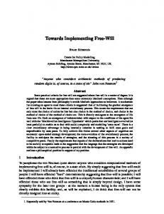
The IEC61499 to address the need for modular and interoperable control applications defines the FB as “an abstraction mechanism that allows industrial algorithms to be encapsulated in a form that can be readily understood and applied by industrial engineers” [3]. The FB consists of a head that is connected to the event flows and a body that is connected to the data flows (see Figure 1). The functionality of a FB is provided by means of algorithms, which process inputs and internal data and generate output data. The execution control chart, a special kind of state transition diagram, specifies the relationships between events and algorithm executions. FB instances, interconnected by event and data connections, constitute the design model of the control application. The control application interacts with the controlled manufacturing process through a set of inputs and outputs, as is shown in Figure 1. Execution Control Event flows
Process inputs
FB1
FB2
FB3
3. THE ENHANCED 4-LAYER ARCHITECTURE For the ET to fulfil the requirements imposed by DCSs we considered the main spaces of the CORFU development process in combination with the 4LCA. The resulting enhanced-4LCA is shown in Figure 2 where we focus on the application and system layers and the realization mapping that is the mapping of the application components to the system layer components. This perspective allows the smooth integration of the CORFU development process with the network topology and infrastructure, and proved to be very important in the identification of the key abstractions that the ET must provide as building blocks of its various diagrams that are used during the modelling process of DCSs. Our main motivation was distribution flexibility and location transparency.
Process outputs
The bottom layer of the enhanced-4LCA is the industrial process layer. Boilers, valves, motors, etc., are the actual real-world plant components that constitute the implementation artefacts of this layer. Abstract software representations of the above real-world artefacts constitute the design diagrams of the controlled industrial process. These diagrams are usually expressed in the form of pipe and instrumentation diagrams. The next layer is the system layer that provides the engineering viewpoint of the DCS. This layer focuses on the underlying computing resources required for the realization of the upper layer that is the application layer. The implementation space of the system layer consists of physical devices such as inteworking units, field devices and field buses as well as logical devices such as VFBs, virtual field devices and logical paths for their interconnections. The design space consists of the abstract software representations of the above artefacts and is used by the CORFU ESS to support the realization mapping i.e. the assignment and downloading processes of the application’s components to the system layer components. These software constructs play, in the developer’s workspace, the role of proxies of the actual real world objects. The next layer, that is the application-layer, is used to represent the required constructs used in the analysis, design and implementation of DCAs. Use case diagrams, object-interaction diagrams, scenario diagrams, class diagrams and FB diagrams, are the most important diagrams used in this layer. Finally, the fourth layer, that is the HMI-layer, captures all the abstractions that concern the development and operational phases of HMI modules.
Data flows
Algorithms Figure 1. Function block instances are interconnected to form the control application.
2.2 The CORFU development process The FB shares, as is very well pointed out in [4], many of the well defined, and already widely acknowledged benefits of the object concept introduced by the object technology. However, the whole approach is procedural like. New advances in software engineering should be considered so as to exploit the maximum benefits introduced by them. Even more, some very important issues are not addressed at all, as for example, the way that requirements are captured and transformed to FB design specifications. To address such issues, we have adopted best practices from component-based development and Object Technology, and utilized them to define the development process of DCAs. The CORFU development process is incremental and is defined as a series of workflows, as described in detail in [10]. We adopted for the analysis phase of DCSs the Unified Modelling Language (UML) [5], which is becoming the lingua franca within the software community [6]. However, we confect the use of the FB construct during the design and implementation phases, since control engineers are familiar with this construct, and field devices and field buses are expected to be compliant with this approach in the near future.
2.3 The CORFU framework
Motivated by the above perspective and to fulfil the tool’s requirements, we have defined for the ET the system-layer editor and a set of application-layer editors. The system-layer editor should allow the engineer to construct in the design space, the system diagram and directly map it to the implementation-space’s artefacts. One of the means used to support such a direct mapping is the device specification, which should be compliant with a
The CORFU framework [9] utilizes ATM, Fast switched-Ethernet or even Gigabit Ethernet to address the integrated development and configuration and to satisfy the real-time constraints of control applications, whose components must be distributed on a variety of field bus segments. Each field bus segment is connected to the backbone through an Interworking Unit (IU) that provides
2
ACM SIGSOFT Software Engineering Notes, Vol. 28, Issue 5 (September 2003) design work. Automatic code generation from the XML specification of the FB design diagrams and the corresponding FB type specifications is under development. An implementation scheme that allows run-time reconfiguration was adopted. The downloading of the produced executable code to the target system in the implementation space, and its corresponding configuration must be as user friendly as possible. The higher layers of the 4LCA must be directly assigned to the real world artefacts and this assignment must be invisible to the control engineer. The required assignment mechanisms are introduced and implemented by the ET in such a way that the encapsulation of all the details of such assignments are of primary concern. For example, for the assignment of a function block instance from the design space of the application layer, to the target field device in the real world layer, the control engineer has only to click on the function block instance and next to click on the icon of the corresponding device in the design space of the system layer. The ET, using the API of the VFB’s configuration management entity, downloads to the device, through the services of the engineering infrastructure and the device’s proxy, the FB type definition in machine-readable format. The ET then issues a “new instance” command to create in the target device in the implementation space of the real world layer, the software module that implements the function block instance.
common device model and accompany the device in a user readable representation such as the one accomplished using XML. This specification is used in the process of appending a field device icon to the design space of the system layer. The engineer, working in the implementation space of the real world layer, connects the field device to the field bus. He/she will then insert, using the corresponding service of the ET, the device’s representation into the design space of the system layer. Then, using the XML field device specification and the appropriate ET functionality, he/she will automatically create the machinereadable device model in the implementation space of the system layer. This is the last step for the realization of the device-proxy’s assignment to the real field device. The ET automatically creates the device-proxy in the implementation space of the system layer. After this assignment the designers are isolated from the details of finding field devices, using the underlying network to communicate with them and so on. Full access to the real device, that is required not only in the development and configuration but even in the operational phase of the DCS (i.e. for reconfiguration), is obtained. An analogous process is followed for each type of component of the system-layer diagram.
4. EXTENDING THE IEC61499 MODEL Working out for the development of the CORFU approach and the CORFU ESS, we were guided to extend the IEC model to cover issues not supported and to modify it to improve the development process in terms of reliability, development time and degree of automation.
4.1 Extensions to the IEC-model The enhanced-4LCA extends the IEC model in the following areas: E1) Capture requirements (functional and non-functional) We adopted the concept of use case to capture functional requirements. Non-functional requirements and mainly FB execution times, processing requirements, relative and absolute deadlines, as well as real-time constraints on event and data connections are easily appended on FB design diagrams, using the stereotype extension mechanism of UML. However, it is not yet determined how these artefacts should be handled by the ET during the distribution, downloading, and configuration phases. In any case, the ET should notify the engineer, during the distribution phase, of the ability of the underlying engineering infrastructure to satisfy the demands that individual elements of software, place on physical and logical devices of the systemlayer [7].
Figure 2. The enhanced-4LCA incorporates the logical model of the control application and the engineering model to facilitate the realization mapping. The design of the control application is fully de-coupled from the physical architecture of the system-layer. A set of editors supports the control engineer in the application-layer. Each editor supports a specific diagram of those met in the application-layer. Industrial Process Terminators (IPTs) and other actors, classes, FBs and data and event connections are the key abstractions and correspondingly the main building blocks of the application-layer diagrams. IPTs will be inserted into the design space of the application layer, to properly define the interaction of the control application with the plant. The IPT instances must directly be mapped to the actual devices that interface the DCS with the controlled processes of the industrial environment.
E2) Transform requirements to function block design specifications We adopted object-interaction diagrams to show the system’s internal objects and the way they collaborate to provide the required behaviour. We next defined a set of transformation rules that fully automates the transformation of requirements captured in the form of use cases into FB design specifications [10].
The ET should provide all the functionality required for the physical distribution of the software building blocks to the system layer components and mainly to field devices and field buses. Developers should be allowed to easily change their distribution scheme as they iterate through the design, without significant
E3) Low-level communication services The Industrial Process Control Protocol, which was defined in the context of the CORFU framework, provides the services required
3
ACM SIGSOFT Software Engineering Notes, Vol. 28, Issue 5 (September 2003) to load, initiate, configure and re-configure FBs. These services are required both for the real-time interaction between VFBs, and for the non real-time interaction of the ET and the HMI modules with VFBs.
5. CONCLUSIONS Our primary objective in the context of this work was to provide a more cohesive process and simplify the development of complex DCAs by hiding complexities associated with field buses and field devices. We adopted the evolving IEC61499 standard and decided to provide an IEC-compliant engineering tool for DCSs, but we found that this model does not address all of the issues involved in such an undertaking. We were guided to propose a number of modifications and extensions to ameliorate the development process. New software technologies were adopted to facilitate the development and deployment of complex distributed control systems. Our 4LCA was enhanced and was used as the basis for the development of a new generation, function block based engineering tool. This architecture satisfies the main goals set by the IEC for the supporting engineering tool, i.e. software encapsulation and re-use, system configuration support and migration of existing software and hardware systems. With the proposed engineering infrastructure, developers of DCSs can focus their efforts on creating the application and not on the realization of the specific distribution scenario. They can easily change, as they iterate through the design, the distribution of the application. The function block design diagrams are fully decoupled from the physical architecture of the system layer. This distribution flexibility is obtained through the location transparency that is forced by the automatic code generation of these parts that utilize the underlying communication subsystems. A prototype of the CORFU ESS engineering tool that is under development using the engineering infrastructure presented in this paper is available for download at http://seg.ee.upatras.gr/corfu.
4.2 Modifications to the IEC-model Modifications introduced by the enhanced-4LCA are related with the use of the following special kinds of FBs that are defined by the IEC standard: • Management function blocks • Service interface function blocks • Event function blocks M1) Management function blocks IEC61499 defines a special kind of FBs, the Management function blocks, and suggest the use of them to load, create and initiate FB execution. Management operations are outside the problem domain and should not be defined by the control engineer. They should be provided by the engineering infrastructure i.e. the CORFU framework in our case. Even more, these operations are not modelled in the best way using the FB construct and we do not proceed this way. Instead, we have defined the Configuration Management Entity (CME) as part of the VFB. We also defined the management services as part of the CME interface provided through a port. This interface is used by the ET to perform the management operations that are related with FBs. The proposed approach results in a more robust implementation and allows the CME functionality to be expanded to cover run-time reconfiguration requirements. M2) Service interface function blocks IEC61499 defines a special kind of function blocks, the Service Interface FBs (SIFBs), to provide interfaces into the underlying communication subsystem. In this way the standard defines how data and event connections of the FB diagram should be implemented. To provide distribution flexibility, and allow our design approach to support location transparency, we do not support service interface FBs. Instead, we have defined a set of services in the engineering infrastructure to be used automatically by the CME, the Real Time Entity and the ET to implement both the event and data connections. This approach a) simplifies the FB design diagrams b) de-couples them from the physical architecture and c) results in a more flexible reconfiguration process that is required during the operational phase. However, we still confect the SIFB construct, which we call Process Interface FBs, to interface with the controlled process.
6. ACKNOWLEDGMENTS We gratefully thank the CORFU development team and especially Chris Tranoris, George Doukas, Polizois Parthimos, and Peter Manesis.
7. REFERENCES [1] Brennan, R, Fletcher, M. and Norrie, D, “An Agent-Based Approach to Reconfiguration of Real-Time Distributed Control Systems”, IEEE Transactions on robotics and automation, vol.18, no 4, August 2002. [2] Heck, B. Wills, L. and Vachtevanos G. “Software Technology for Implementing Reusable, Distributed Control Systems”, IEEE Control Systems Magazine, February 2003. [3] IEC Technical Committee TC65/WG6, “IEC61499 Industrial-Process Measurement and Control – Specification”, IEC Draft 2000. [4] Lewis, R. Modelling control systems using IEC 61499, The Institution of Electrical Engineers 2001. [5] Rumbaugh, J. Jacobson, I. G.Booch, “The UML Reference Manual”, Addison Wesley 1999. [6] Selic, B. “Turning Clockwise: Using UML in the Real-Time Domain”, Communicat. of the ACM, Oct.99, vol.42, No. 10. [7] Selic, B. “A Generic framework for Modelling Resources with UML”, IEEE Computer, June 2000, vol.33, No 6. [8] Thramboulidis, K. C. Tranoris, “An Architecture for the Development of Function Block Oriented Engineering Support Systems”, IEEE CIRA, Canada 2001.
M3) Event function blocks The standard defines a set of event function blocks that allow a wide range of different event scenarios to be modelled. Event function blocks such as event splitter, event merger, event rendezvous etc. are predefined and ready to be used by the designer. To simplify the function block design diagram and improve the performance of the resulting DCS, we defined an event-API that should be provided by an IEC compliant device. For the design time, the function block design editor of the ET provides a palette with event icons that are used by the designer to import in his model different event scenarios. Later, during the realization of the application model, the ET automatically configures the device, through the configuration event-API, to provide the required behaviour during the operational phase. This approach results in simplified function block diagrams and, improves the performance of the control application.
4
ACM SIGSOFT Software Engineering Notes, Vol. 28, Issue 5 (September 2003) [9] Thramboulidis, K. “Development of Distributed Industrial Control Applications: The CORFU Framework”, 4th IEEE International Workshop on Factory Communication Systems, Sweden, August 2002. [10] Tranoris, C. K. Thramboulidis, “From Requirements to FB Diagrams: A new Approach for the Design of Industrial Control Applications”, 10th Mediterranean Conference on Control and Automation, Lisbon, Portugal, July 2002.
5