Towards an FCA based tool for visualising Formal Specifications Thomas Tilley University of Queensland, School of Information Technology and Electrical Engineering, Brisbane, Australia
[email protected]
Abstract. This paper describes an approach to visualizing Z specifications based on Formal Concept Analysis (FCA). The approach takes a source specification written in LATEX and produces a formal context representing the static structure of the specification. The corresponding formal concept lattice can be used to investigate and explore various properties of the specification. The line diagram does not replace, but is intended to be used in conjunction with, the original Z specification. Abstraction through conceptual scaling, nesting, zooming and folding line-diagrams allow users to retain context while navigating large specifications. An example based on Spivey’s classic BirthdayBook specification is presented and the development of a prototype visual specification browser is described.
1
Introduction
Specifications are a communication tool used to document properties of interest in a particular information system. They serve as a common reference point for requirements gatherers, the implementors of a system and its ultimate users. Formal specifications do this in a rigorous manner that attempts to remove ambiguity and lends itself to analysis. The Z notation is a state-based formal specification technique based on set theory. Typically specifications written in Z are “marked up” using LATEX because of the mathematical nature of the notation. Herein lies a problem. A specification needs to be understood by all those using the system but the complexity and mathematical nature of Z makes this difficult particularly for clients discussing a specification. One way of addressing this problem is to provide alternative graphical or visual representations of the specification that may be more easily understood by all participants. This paper describes an approach to visualising Z specifications based on Formal Concept Analysis (FCA) - a lattice based data analysis technique [8]. The approach takes a source specification written in LATEX and produces a line diagram or formal concept lattice that represents the static structure of the specification. The line diagram does not replace, but is intended to be used in conjunction with, the original specification. The lattice provides abstraction and
2
Thomas Tilley
context for users navigating large specifications and various properties of the specification can be identified and explored using the diagram. The next section of the paper briefly introduces the Z notation and then Section 3 discusses the continued call for Formal Methods tool support. Section 4 describes the applicability of FCA to support formal specification and an example based on Spivey’s BirthdayBook specification [21] is presented. Section 5 extends the example and describes the development of an FCA based tool to visualise Z specifications before Section 6 concludes the paper.
2
Formal Specification in Z
Formal Methods can be broadly defined as tools and notations with formal semantics that support the unambiguous specification of the requirements for a computer system. They provide a means by which the completeness and consistency of a specification can be explored as well as proofs of correctness for implementations of the specification [23, 4]. The application of Formal Methods can be of benefit to specifiers, implementers, and testers by providing unambiguous communication, verification, validation, and in some cases mechanized code generation [22]. The “formal” in Formal Methods denotes the ordered and deliberate application of mathematically rigorous processes to the act of specification. Z is a state based formal method that exploits set theory and first order predicate logic. As a result of the mathematical nature of the notation most Z tools are comprised of at least a formatting package for LATEX and a typechecker. Specifications in Z are composed of named schema boxes that describe operations by their input/output behaviour. Schema are divided into an upper region called the declaration-part and a lower region called the predicate-part or more correctly the formula-part. Variables and their respective types are declared in the upper region while the lower region contains predicates describing preconditions and post-conditions for the current operation. Models are constructed by specifying and composing a series of schemas and schemas can be refined to reflect the desired level of system abstraction. An example schema from Spivey’s “BirthdayBook” specification appears in Figure 1.
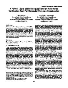
Fig. 1. The AddBirthday schema from the BirthdayBook specification.
Lecture Notes in Computer Science
3
The BirthdayBook specification provides an introduction to the Z notation and describes a simple reminder system for recording people’s birthdays using a set of names and a set of dates. New birthdays are added to the system via the AddBirthday schema in Figure 1 which takes a name and date as input. The declaration ∆BirthdayBook indicates that this schema describes a state change (as opposed to “Ξ” operations which do not change the state of the system). If the input name does not already exist in the set of known people then the name and date are added to the set of birthdays. This style of formal specification allows certain properties of a system to be proved. The behaviour of a system can also be explored without actually implementing the system itself. While there can be significant advantages obtained by integrating Formal Methods like Z into the production of software artefacts there is also an associated cost.
3
Increasing the Usability of Formal Methods
Despite the potential benefits offered by the integration of formal methods into software development there still continues to be limited adoption in industries outside those writing safety critical software. Despite attempts to dispel some of the “myths” about formal methods [11, 3] a number of them live on. In particular the myths that “formal methods require highly trained mathematics” and that “formal methods are unacceptable to users”. To address this problem there have been a number of approaches that provide alternative visual representations of specifications for Z-like languages that have both textual and graphical components within their notation. UML [2] has become the de facto industry language for modelling systems. While it provides a means of specification it does not have the mathematical rigor of formal methods. On the other hand it enjoys a popularity that formal methods do not and its graphical nature make it an obvious choice as an alternative representation language. UML is also implementation oriented which may be helpful to the ultimate implementers of a particular model, however, this is ultimately inconsistent with the aims of a conceptual modelling language [15]. There have been a number of approaches used to introduce graphical representations of Z specifications via UML. The work of Sun, Dong, Liu and Wang [12] provides an XML mapping for Object-Z [20], an object-oriented extension of Z, that can then be transformed into UML. Their approach also provides a browser-based environment for viewing specifications which is described further in Section 5. Kim and Carrington [16] also use UML for visualising Z specifications. Beyond the static structure of the specification they argue that for a full understanding of a specification the dynamic nature and complex constraints must also be visualised. To accomplish this they introduce two other graphical representations in addition to UML — one for the complex constraints and another for the operation schemas.
4
Thomas Tilley
Alloy is a Z-related, lightweight formal method with both textual and graphical components that offer a straightforward mapping from UML into a formal notation [14] [13]. Lightweight formal methods are “lightweight” in that they offer “less than completely formal” or partial approaches to specification, validation and testing [1, 14]. Typically they trade off completeness or language functionality for efficiency. Alloy has tool support for both the editing and analysis of specifications. As Alloy and the formal methods tools database 1 on the WWW demonstrate there is some existing tool support for formal methods, however, there continues to be a call for new tools [12]. These calls cite a need not only for tools that have matured from research prototypes into robust, commercial quality software [5, 17], but also for functionality that is not currently supported. There is a need for tools that can present comprehensible specifications and proofs for large systems at different levels of abstraction: One important problem in current formal methods is that in practice it is difficult to relate formal views of the same system at different levels of abstraction. If we had better practical solutions to this problem, it might be easier to apply formal methods at many stages during the development of a large system [9]. In support of this, Clarke and Wing in their paper on the state of formal methods and future directions list abstraction as a fundamental concept that requires further work: Real systems are difficult to specify and verify without abstractions. We need to identify different kinds of abstractions, perhaps tailored for certain kinds of systems or problem domains, and we need to develop ways to justify them formally, perhaps using mechanical help [6]. Clarke and Wing go on to list a number of criteria that methods and tools should attempt to address including ease of use, efficiency, and focused analysis. They argue that tools and their output should be as easy to use as compilers. The time taken for analysis should be comparable to that of compilation and individual tools need not be good at analyzing all aspects of a system, but they should analyze one aspect well. The next section of the paper introduces Formal Concept Analysis as a mechanism for visualising the structure and properties of Z specifications. This mechanism forms the basis of a tool that attempts to address a number of the requirements for formal methods tool support outlined above.
4
FCA support for Formal Specification
FCA is the process of describing the world in terms of objects and the attributes which may be possessed by those objects. The line diagrams resulting from these 1
See http://www.fmeurope.org/databases/tools.html
Lecture Notes in Computer Science
5
descriptions provide an alternative graphical representation of tabular data that is relatively intuitive to use and navigate. Descriptions in FCA are triples consisting of the set of objects, the set of attributes and an incidence relation between objects and attributes. The triple is known as a formal context and is written (G, M, I) where G is the set of objects, M is the set of attributes and I is the incidence relation between G and M . The letters G and M are taken from the German words “Gegenst¨ande” and “Merkmale” which translate to “objects” and “attributes” respectively. The relation I is a subset of the cross product between these two sets, I ⊆ G × M . If an object g has attribute m then g ∈ G is related by I to m and we write (g, m) ∈ I or gIm. A formal context can be represented as a cross-table where the columns are attributes, the rows are objects and the relation between them is indicated by the presence of crosses. Table 1 presents a formal context based on the BirthdayBook specification [21].
Table 1. A cross table or formal context representing the BirthdayBook specification. Here the schema names are taken as objects and the Z character strings as attributes.
In this example the schema names are considered as objects and the attributes of interest are the LATEX mark-up for the Z character strings of the specification. This is analagous to the text-data mining approach used in [19] where individual schemas could be considered as documents and the mark-up elements as document terms. An ‘×’ at a particular location or cell in the cross table indicates that an object has that particular attribute. For example, the “AddBirthday” schema shown in Figure 1 has the attributes “known”, “NAME”, and “birthday”, among others. Conversely a blank cell in the context indicates that the object does not have that attribute. The notion of a concept is introduced as a pair (A, B) where A ⊆ G is a subset of the objects, B ⊆ M is a subset of attributes, and both A and B are maximal with respect to I. In order to define what maximal means we need to introduce the derivation operator, denoted A0 when applied to the set A.
6
Thomas Tilley
The derivation operator may be applied to either a set of objects, or a set of attributes. Its two definitions are: A0 = {m ∈ M | ∀g ∈ A : gIm} B 0 = {g ∈ G | ∀m ∈ B : gIm}
(1) (2)
The derivation of a set of objects, denoted A0 , contains all attributes that are possessed by all the objects in A. Similarly, the derivation of a set of attributes B 0 , includes all objects that have all the attributes in B. For a pair (A, B) to be a concept of a given formal context it must be the case that A = B 0 and B = A0 . A pair (A, B) is a concept of the formal context (G, M, I) if and only if A ⊆ G, B ⊆ M , A0 = B and B 0 = A. The set A is called the extent of the concept and the set B is called the intent of the concept. The set of concepts of a formal context forms a lattice which is called the concept lattice and for any complete lattice there is an isomorphic concept lattice [8]. 4.1
A Lattice of Concepts
A smaller context based on a subset of the attributes in the BirthdayBook specification is presented in Figure 2. The schema names are again considered as objects but only a subset of the attributes are used, representing the basic data types ‘NAME’, ‘DATE’ and ‘REPORT’.
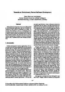
Fig. 2. Formal context and the corresponding concept lattice for the BirthdayBook specification using the schema names as objects and only the basic data-types as attributes.
This concept lattice contains 6 concepts the most general of which is at the top of the diagram. This concept is the pair ({InitBirthdayBook}, {}). The most specific concept is at the bottom of the diagram. This is the pair ({RAddBirthday, RF indBirthday, RRemind}, {N AM E, DAT E, REP ORT }) which represents the concept of objects possessing all attributes. The diagram
Lecture Notes in Computer Science
7
also illustrates a specialization ordering over the concepts denoted by ≤. The concept (A1 , B1 ) ≤ (A2 , B2 ) if A1 ⊆ A2 or equivalently B2 ⊆ B1 . The attribute labels of a concept are typically drawn above the concept node while the object labels are drawn below. Drawing the complete intent and extent for each concept would clutter the diagram, however, line diagrams can be labelled in an economical way. For each attribute m there is a maximal concept with respect to the specialization ordering that has m in its intent. More specific concepts will also have m in their intents. By attaching attribute labels to maximal concepts in the diagram the intent of a concept may be determined by collecting attribute labels from the more general concepts. For example, the intent of the concept “AddBirthday” can be recovered by traversing upward paths in the lattice to collect the attributes ‘DATE’, and ‘NAME’. Similarly, object labels appear with their most specific, or minimal, concepts. The extent of a concept can then be determined by collecting object labels along the downward paths from the concept in question. Traversing downward paths through the line diagram in Figure 2 from the attribute ‘REPORT’ collects: ‘Success’, ‘NotKnown’, ‘AlreadyKnown’, ‘RAddBirthday’, ‘RFindBirthday’ and ‘RRemind’. These are the schemas that contain the data-type ‘REPORT’. While a line diagram provides an alternate visual representation of a formal context there is no loss of data. The formal context is contained within the diagram so the original data can be recovered directly from it. The line diagram can be used to navigate the specification or to reveal certain properties. For example, to find all schemas that contain both the ‘DATE’ and ‘REPORT’ attributes we traverse down the lattice from the concepts labelled ‘DATE’ and ‘REPORT’ which meet at the concept with the extension labelled ‘RAddBirthday’, ‘RFindBirthday’ and ‘RRemind’. The diagrams exploit human visual processing and can be used with minimal training, however large diagrams quickly lose their usability because of their size and visual complexity. Even the line diagram representing the formal context in Table 1 is barely useable because of its size. FCA can, however, be applied to larger specifications by exploiting a number of abstraction techniques. 4.2
Abstraction Mechanisms
There are a number of abstraction mechanisms that can be used to reduce the visual complexity and size of line diagrams. As an alternative to rendering the entire lattice, only those parts of current interest need be shown. This can be achieved by dynamically collapsing or unfolding parts of the diagram to hide or reveal information. Folding line diagrams can be used to represent large lattices where the whole diagram is represented initially as a single concept node. As attributes of interest are identified the lattice unfolds to display those concepts. In particular this mechanism can provide users with a perspective on the position of a given schema within the setting of a large specification. Conceptual scaling is another abstraction technique that can be used to reduce the visual complexity of lattices. Conceptual scales cluster attributes together within a formal context and the scales are themselves formal contexts.
8
Thomas Tilley
For example, Figure 3 presents a formal context and the corresponding concept lattice if we only consider the basic schema declarations ∆ (‘Delta’) and Ξ (‘Xi’) as attributes. Figures 2 and 3 both contain all the objects from the BirthdayBook specification however they are clustered based on different attributes of interest.
Fig. 3. Cross table of the BirthdayBook specification using the schema names as objects and the schema operations ∆ (’Delta’) and Ξ (’Xi’) as attributes. The corresponding line diagram shows the object frequency in each contingent.
Scales can also be composed to produce a nested line diagram where one scale is nested inside another. Composing the lattices from Figures 2 and 3 produces the nested line diagram shown in Figure 4 where the inner scale represents the basic data-types and the outer scale the schema operation types. In a Z specification the state of the system can only be changed via ∆ operations. From the outer, leftmost concept in the nested line diagram it can be seen that the only ∆ operations in the BirthdayBook specification are the schemas “AddBirthday” and “RAddBirthday”. Spivey’s example is purely illustrative and a person’s birthdate does not change, however, there is typically a need in most systems for deletion and update as well as insertion. For example, an ultimate user of the BirthdayBook system may no longer need to be reminded about their ex-bosses birthday and may wish to remove it. The inability of the system to remove birthdays can be observed because of the way the schemas are clustered. Applying conceptual scales facilitates the interactive exploration of questions about a specification. Scales can be nested to arbitrary depth but beyond a single level of nesting the diagrams typically become too small to be useable. The scales themselves can be predefined on a per-project basis (for example, the data-type scale in Figure 2) or based upon Z language constructs (for example, the schema operation scale in Figure 3). Alternatively scales can be generated on demand by the
Lecture Notes in Computer Science
9
users themselves. This technique has been demonstrated in a FCA based email management system [18].
Fig. 4. Nested line diagram showing the scale from Figure 2 nested inside the scale shown in Figure 3.
The contexts presented here represent simple “part of” relationships, however, via conceptual scaling FCA can also be applied to multi-valued contexts where objects have attributes with values [8]. As a further example of applying FCA to the static structure of a specification consider the concept lattice in Figure 5. This lattice corresponds to the context where the schema names from the BirthdayBook specification are considered as both the set of objects and the set of attributes. Here gIm represents schema g containing a reference to schema m. The concept lattice represents a form of inheritance or schema composition within the BirthdayBook specification. For example, schemas that use the “Success” operation can be found by starting at the concept labelled “Success” at the right hand side of the diagram and traversing downward paths to recover the schemas: “RAddBirthday”, “RRemind”, and “RFindBirthday”. Note that only the cardinality of the contingent is shown — in this example for each object g the object concept of g is the same as the attribute concept of g. As a second simple example, all the schemas contained within a particular schema can be recovered by traversing the upward paths through the lattice. In Figure 6 both the ideal and filter of “RAddBirthday” are highlighted. Travers-
10
Thomas Tilley
Fig. 5. Formal concept lattice for the context using the BirthdayBook specification schema names as both objects and attributes. This diagram represents schema composition within the BirthdayBook specification.
ing upwards from RAddBirthday recovers the schemas: “AlreadyKnown”, “AddBirthday”, “BirthdayBook”, and “Success”. The visualisations presented here only represent static structure but they provide the basis for exploration and navigation of the formal specification. While rendering the whole lattice for even simple specifications is typically not helpful the ability to represent only those attributes of interest or to view multiple scales via nesting allows even large specifications to viewed in a useful manner. The next section of the paper describes a tool that exploits these ideas to facilitate the interactive, user-driven exploration of Z specifications.
5
Navigating Specifications with FCA
This section describes a method for interactively exploring Z specifications based on ZML [12], an XML representation of Z, and the open-source, cross-platform FCA tool ToscanaJ 2 . An overview of the process is presented in Figure 7. Z specifications are traditionally written in LATEX and viewed as postscript or PDF documents—the context in Table 1 was generated by parsing a LATEX version of the BirthdayBook specification. A more recent alternative for “markingup” specifications is ZML, an XML representation of Z. Specifications written in ZML have the advantage that they can be transformed using XSL stylesheets into HTML which can be rendered in a Web browser. Specifications can then be 2
See http://toscanaj.sourceforge.net
Lecture Notes in Computer Science
11
Fig. 6. The concept lattice from Figure 5 with the extent and intent of the “RAddBirthday” schema highlighted.
Fig. 7. Overview of the specification browsing system.
12
Thomas Tilley
easily accessed in an on-line form complete with HTML anchors and hyperlinks for navigation as shown in Figure 8. A URL specifying an HTML anchor within a ZML document can be used by an external tool to link directly into and display any part of a Z specification.
Fig. 8. Browser rendering of the BirthdayBook specification showing the AddBirthday schema from Figure 1.
ToscanaJ is a FCA tool for rendering concept lattices that supports extent/intent highlighting, conceptual scaling, nesting, and zooming [7]. Lattices are input using an XML file format called CSX which stands for “Conceptual Schemas”. ToscanaJ provides an extensible “view” interface that allows custom object views to be specified within the CSX file. These views allow users to click on the object labels in a line diagram and display additional information. This view interface can be exploited to display a Z specification by launching a URL containing a reference to the ZML version of the specification with the object name as an anchor. The total process to browse a Z specification via FCA then proceeds as follows. Firstly, the original Z specification must be converted into ZML. A tool to do this has been written and some existing Z tools such as CADiZ provide the ability to export Z in an alternate XML format 3 . The ZML version of the specification is then parsed and stored in a database that is used to construct the CSX file. Currently this process is performed manually using the FCA tool Anaconda and a converter but an editor is currently being developed for ToscanaJ. The CSX file also includes any predefined scales that the user may wish to apply. Once the CSX file has been created the user can use ToscanaJ to explore the 3
See http://www-users.cs.york.ac.uk/∼ian/cadiz/
Lecture Notes in Computer Science
13
concept lattices representing the specification. Clicking a schema name on the lattice diagram will launch a web-browser displaying the schema in the original specification. This fulfills the aim of providing an FCA based alternate visual representation that can be used alongside existing tools. While the CSX files must currently be prepared manually the ZML and database creation can be performed in times comparable with compilation from a LATEX source specification.
6
Conclusion
This paper has described an approach to visualising Z specifications via formal concept analysis - a lattice based data analysis technique that has already been successfully applied in a number of research areas. While it is not useful to render whole lattices, conceptual scaling, nesting and folding line diagrams provide abstraction and context that allow large specifications to be viewed and navigated in a helpful way. There is a continued call for tool support for formal methods and the work described here is the basis for a prototype visual specification browser currently under development. Future directions for this work include an analysis of which Z keywords and mark-up elements are required to produce useful contexts and pre-defined conceptual scales. While the approach described in this paper takes a text data mining approach to produce concept lattices the use of Power Context Families [10] to exploit the structure and semantics of Z is also being explored.
References 1. S. Agerholm and P.G. Larsen. A lightweight approach to formal methods. In D. Hutter, W. Stephan, P. Traverso, and M. Ullman, editors, Applied Formal Methods – FM–Trends 98, LNAI 1641, pages 168–183, Berlin, October 1998. Springer Verlag. 2. G. Booch, I. Jacobson, and J. Rumbaugh. The unified modeling language user guide. Addison-Wesley object technology series. Addison-Wesley, Reading, Massachusetts, 1999. 3. J.P. Bowen and M.G. Hinchey. Seven more myths of formal methods. IEEE Software, 12(4):34–41, July 1995. 4. J.P. Bowen and M.G. Hinchey, editors. Applications of Formal Methods. Prentice Hall, London, 1996. 5. R.W. Butler and C.M. Holloway. Impediments to industrial use of formal methods. IEEE Computer, pages 25–26, April 1996. 6. E.M. Clarke and J. Wing. Formal methods: State of the art and future directions. ACM Computing Surveys, 28(4):626–643, December 1996. 7. R.J. Cole and P.W. Eklund. Browsing semi-structured web texts using formal concept analysis. In Proceedings 9th International Conference on Conceptual Structures, LNAI 2120, pages 319–332, Berlin, 2001. Springer Verlag. 8. B. Ganter and R. Wille. Formal Concept Analysis - Mathematical Foundations. Springer-Verlag, Berlin, 1999.
14
Thomas Tilley
9. S. German. Research goals for formal methods. ACM Computing Surveys, 28(4es), December 1996. 10. B. Groh and P. Eklund. Algorithms for creating relational power context families from conceptual graphs. In W. Tepfenhart and W. Cyre, editors, Conceptual Structures: Standards and Practices, Lecture Notes in Artificial Intelligence, pages 389–400, Berlin, 1999. Springer Verlag. 11. A. Hall. Seven myths of formal methods. IEEE Software, pages 11–19, September 1990. 12. J. Lui J. Sun, J.S. Dong and H. Wang. Object-Z web environment and projections to UML. In WWW10 - 10th International World Wide Web Conference, pages 725–734, New York, 2001. ACM. 13. D. Jackson. A comparison of object modelling notations: Alloy, UML and Z. Unpublished Manuscript, August 1999. 14. D. Jackson, I. Schechter, and I. Shlyakhter. Alcoa: the alloy constraint analyzer. In Proceedings of the International Conference on Software Engineering, pages 730– 733, Limerick, Ireland,, June 2000. 15. D. Jackson and M. Vaziri. Some shortcomings of OCL, the object constraint language of UML. http://sdg.lcs.mit.edu/∼dnj/publications.html, December 1999. 16. S. Kim and D. Carrington. Visualization of formal specifications. In Sixth AsiaPacific Software Engineering Conference, pages 38–45, Los Alamitos, California, December 1999. IEEE Computer Society. 17. University of Delaware Protocol Engineering Laboratory. Protocol specification in Estelle at univ of delaware. http://www.eecis.udel.edu/∼amer/PEL/estelle/index.html, April 2000. 18. P. Eklund R. Cole and G. Stumme. CEM – a program for visualization and discovery in email. In D.A. Zighed, J. Kormorowski, and J. Zytkow, editors, Proceedings of PKDD 2000, LNAI 1910, pages 367–374, Berlin, 2000. Springer Verlag. 19. R.J.Cole and P.W.Eklund. Analyzing an email collection using formal concept analysis. In European Conference on Knowledge and Data Discovery, PKDD’99, LNAI 1704, pages 309–315. Springer Verlag, 1999. 20. G. Smith. The Object-Z Specification Language. Advances in Formal Methods. Kluwer Academic Publishers, 1999. 21. J.M. Spivey. The Z notation : a reference manual. Prentice-Hall International, 1989. 22. K.J. Turner, editor. Using Formal Description Techniques (An Introduction to Estelle, LOTOS and SDL). Wiley series in Communication and Distributed Systems. John Wiley and Sons Ltd., Chichester, 1993. 23. Robert Vienneau. A review of formal methods. In M. Dorfman and R.H. Thayer, editors, Software Engineering. Computer Society Press, 1996.