Towards an Increased Reusability of Distributed Control Applications Modeled in IEC 61499 Ingo Hegny1 , Thomas Strasser2 , Martin Melik-Merkumians1 , Monika Wenger1 , Alois Zoitl1 1
Vienna University of Technology, Automation and Control Institute, Vienna, Austria {hegny, melik-merkumians, wenger, zoitl}@acin.tuwien.ac.at 2
AIT Austrian Institute of Technology, Energy Department, Vienna, Austria
[email protected]
Abstract Reusability of control code is crucial for future industrial automation in order to allow the development of high quality control systems in less time and with less cost. A key stopper for automation software reuse is the current intertwining of control logic with hardware specific code. Existing approaches that tackled such a problem could lead to improvements but will not sufficiently solve this issue. In this work we investigate a concept based on a logical grouping of I/Os to so called Instrumentation- and Control-Points and decoupling them from the control application by applying IEC 61499’s adapter concept. In two industrial motivated application examples we show that this concept fulfills the requirements for increasing the reusability of control code by separating control logic from hardware specific code. Moreover, it leads to a better application software structure which is easier to maintain and to understand.
1. Introduction Constantly changing customer requirements in the manufacturing domain (e.g., flexible manufacturing systems) but also in other areas like the logistics sector, the energy area, and in building automation demand for flexible architectures and concepts. Prevalent control systems, implemented according to the scan-based IEC 61131-3 Programmable Logic Controller (PLC) standard [12], lack the ability to easily adapt to new requirements. Process interfaces are typically represented as global variables in the process image which is updated once per cycle. The cycle time is on one hand dependent on the control hardware and the requirements imposed by the controlled process and on the other hand has a big influence on the execution performance of the overall application. The event-based execution paradigm of IEC 61499 [13] and the encapsulation of functionality into Function Blocks (FBs) are enablers for flexible control sys-
tems. Especially, the well-defined interfaces of the FBs, the component-based approach for the design of control applications, and the intentional absence of global variables—prohibiting hidden interfaces—foster the reuse of previously implemented functionality [23]. The comprehensive state-of-the-art overview provided by Vyatkin [27] shows that the industrial application of IEC 61499 based control systems is steadily increasing. Control systems for building automation, logistic-systems (e.g., luggage handling) as well as process industry (e.g., carbamide production for fertilizers) are operational [19]. Feasibility studies give a strong indication for the aptitude of IEC 61499 for Smart Grids applications. The reactive and real-time compliant layer that is directly interacting with the electrical equipment can be implemented efficiently with IEC 61499 [11, 31, 32]. The integration of optimizing control algorithms (e.g., Model-Predictive Control) as shown in [29] will further broaden the industrial applicability of IEC 61499. Important characteristics, that were formulated during the creation of the IEC 61499 standard, are: (i) interoperability, (ii) portability, and (iii) configurability. Interoperability in the standard’s sense means multiple devices from different vendors can easily be used within a single automation project. Especially the data and event exchange between all involved devices can be done with elements and concepts defined in the standard. Portability between several engineering tools is provided, if an automation project (consisting of control application, devices, and mapping information), developed within an IEC 61499 compliant tool, can be used in another tool without loss of information. The third feature, configurability, is the ability to use any IEC 61499 compliant engineering tool to deploy control applications to any IEC 61499 compliant device (i.e., execution platform for FBs). Nevertheless, the fulfillment of all three properties does not automatically imply reusability of once developed control applications. Changing the control platform (e.g., control hardware, run-time environment) can impose additional effort to re-engineer the application.
SIFB
SIFB
Controlled Process
SIFB
Control Application
SIFB
SIFB
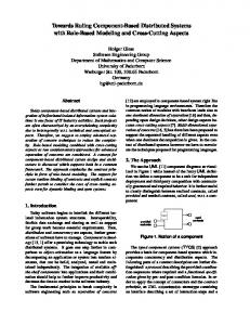
Figure 1. Service Interface Function Blocks in a control application providing access to the controlled process Within control applications interfaces to external entities (e.g., process interfaces, network handlers) are explicitly provided by Service Interface Function Blocks (SIFBs). They have been introduced as special kind of FBs in IEC 61499 [13]. SIFBs are allowed to be used like any other FB in the design of control applications. A schematic of a control application using SIFBs to interact with the controlled process is shown in Fig. 1. However, the use of hardware dependent SIFBs limits the hardware-independence of the designed control applications. Even apparently hardware-independent Composite Function Blocks (CFBs) can be rendered hardwaredependent, if the included function block network contains a SIFB. Such hidden hardware or process interfaces hinder the reuse of software components. In this paper we investigate how to improve the reusability of IEC 61499 control applications and application parts by a better separation of control functionality from hardware specific functionality. For this we start with an analysis of existing approaches on hardware access in IEC 61499, which is followed by an investigation on the application of the Model-Driven Architecture (MDA) approach. Moreover, we present our proposed approach and show its applicability in selected application areas. A summary of the results and an outlook conclude this paper.
needed in addition are design patterns that guide control engineers in how to structure their control application in order to increase the reusability. 2.1. SIFB Nested in Control Applications With the limited set of current execution platforms and control devices, engineers and researchers develop their applications for specific devices. Two separate steps of control design in IEC 61499—hardware-independent application development and mapping to specific devices and available I/Os—are often intertwined. As long as the targeted execution platform (e.g., fieldbusses, internal backplanes) are well known, this approach will lead to fast results. Hardware-specific SIFBs are directly used in control applications design [5, 26]. Hence, the control applications are tailored to a specific configuration of the control system (see Fig. 2). However, the reuse of such control applications on other hardware is limited. All SIFBs used in the control application have to be either approved or replaced by another SIFB, provided by the new control platform. This re-engineering process is currently not well supported by engineering tools [4]. However, adopting the control application to the new control system configuration does not solve the problem permanently. Each change in the control system triggers a new re-engineering process. Even more, the hardware dependencies can be part of the inner FB network of CFBs. This is a common practice in actual application implementation. CFBs have been introduced for hierarchically structuring control applications and to encapsulate existing functionally provided by other FBs. They are self contained, typed entities, which are characterized by their specified interface. Their behavior is dependent on the internal network of contained FBs, which shall fulfill the defined behavior at the interface [13]. As SIFBs can be used as any other FB in control design, it is also allowed to include them in the internal FB networks of CFBs. Such hidden interfaces inhibit the reuse on other platforms. During the reengineering process to use the same control application on a new type of hardware, the inner FB network of all START
BUTTONS
COLD WARM
E_RESTART
INITO CNF
READ_2 DO1 DO2
2. Process Interfacing in IEC 61499
POSITIONS PERIODIC
Control application design with IEC 61499 has been investigated by research for more than ten years now. Increasing reusability has always been one of the main driving forces not only behind IEC 61499 but also behind the research on utilizing IEC 61499 for control application development. IEC 61499 tackles this issue with the paradigm of device independent modeling of distributed control applications and a late mapping to the control devices (also known as “application-centered engineering”). However, this paradigm by itself is not enough. What is
INIT REQ
START
EO
E_CYCLE ...
INIT REQ
INITO CHG
ENCODER LP MP RP
DT
CONTROLLER INIT BTN SENS LIGHT
INITO EO
INITO CNF
WRITE_2
CYLINDER_CTL START MODE HOME MID END ON
ACTUATORS INIT REQ
LEFT RIGHT LED OPMOD
DI1 DI2
MODE_DISP INIT REQ
INITO CNF
WRITE_2 DI1 DI2
LIGHT INIT
INITO CNF
READ_1 DO1
Figure 2. Typical Control Application with nested SIFBs according to [26]
2.2. Utilizing Local Multicast Design Pattern In order to obtain a platform independent representation of IEC 61499 applications Thramboulidis [24] developed the concept of Industrial Process Parameters (IPP) which are a kind of parameters of the underlying process. Therefore, the usage of IPP is being introduced into the IEC 61499 concept in order to divide the control application from the I/O access. The I/O access is modeled also by IEC 61499 FBs and the resulting application is called Process Interface FB Diagram. A very similar approach is discussed by Landsteiner et al. [16]. They propose to perform a separation of a FB network into (i) a control
Control Application
used CFBs may need to be checked recursively. Hence, a good design principle is to encapsulate only hardwareindependent functionality in CFBs [28, 33]. To overcome the need to replace all SIFBs if the control hardware is changed, generic I/Os might be used [4, 10]. The main idea is to provide SIFBs with standardized FB interfaces (e.g., digital input, digital output) on multiple platforms. Hence, the FB network of the control applications can be deployed without changing FBs. The feasibility of the approach was shown on 4 different hardware platforms [4]. The generic SIFBs for digital input and output as well as analogue input and output are provided as hollow shells. During the configuration and compilation of the run-time environment FORTE for a specific hardware platform, device-dependent code is included. Thus, hardware specific SIFBs with generic interfaces towards the control application are included in the IEC 61499 compliant run-time environment. The run-time system needs configuration data to know, where to read or write process data. Since the number of parameters is dependent on the actual implementation (e.g., module, slot, port), all data is encoded into a single string variable. A special data input PARAMS is used to hand this information to the run-time system [4], as can be seen in Fig. 3. Two drawbacks can be identified for these approaches: First, for different run-time environments (e.g., FBRT [2]) the same effort has to be taken. Otherwise one is limited in the selection of devices. Second, the control application still has to be altered, as hardware-specific parameters have to be provided at the interface of the SIFBs.
I/O Application
Figure 3. Generic SIFBs for reading and writing single values [4]
application, and (ii) an I/O application as depicted in 4. As we will see later on this approach can be seen as kind of a MDA-like development approach. The control application covers mainly control tasks and has no hardware-dependent FBs. Therefore, it can be considered as the Platform-Independent Model (PIM). The hardware access (e.g., analog/digital I/Os) is provided by SIFBs within the I/O application. Therefore, the I/O application can be seen as the Platform-Definition Model (PDM). With the mapping of the application to the Devices and Resources the Platform Specific Model (PSM)/Implementation Specific Model (ISM) can be obtained. The interface between the control and I/O application is also defined via IEC 61499 SIFBs. The authors in [16] propose the Local Multicast design pattern using the PUBL/SUBL SIFBs [2] to link the control and I/O application. However, an extension to network communication using UDP multicast is possible. Although this approach has the advantage that no platform specific FBs are used in the control application, its major drawback lies in the configuration of the communication channels within the hardware-specific application, especially when the hardware-dependent SIFBs are hidden within several layers of CFBs. In order to overcome this limitation the industrial IEC 61499 implementation of nxtControl [19] is using socalled SymLinks [19]. These are from a general perspective similar to the presented concepts of separating I/O access from control applications. The main advantage of the SymLinks concept is that on the control application side they are automatically configured based on the FB hierarchy they are used in. Therefore, a control engineer only has to configure the I/O access side after the application mapping, greatly reducing the overall configuration effort. The main drawback of all the approaches presented in this section is that the interface to the I/Os is always somewhere hidden and not directly visible. Hidden interfaces render software components hard to use and reuse [23]. It is hard to identify the parts of a control application which are interacting with the hardware. Generally speaking
Figure 4. Platform independent representation of control applications using the Local Multicast design pattern [16]
with these approaches the global variables banished from IEC 61499 have been reintroduced in a slightly more regulated form. Finally, the presented concepts do not allow any checking if both sides are expecting the same data type and even further, if not several application parts trying to set the same output, which would lead to undefined system behavior. 2.3. Component Decoupling using Adapter Interfaces Adapter interfaces are a concept defined in IEC 61499 which are currently not very widely used by the community. The adapter concept allows defining a certain FB interface (i.e., combination of event and data I/Os) as common interface and using this in FBs interfaces either as adapter provider (i.e., plug) or as adapter acceptor (i.e., socket). The main advantage of adapters are just often seen as the combination of the event and data connections to one cable, reducing the amount of connections in IEC 61499 applications. However they have the great advantage that adapters completely separate both sides (i.e., provider and acceptor), allowing to implement and to test them independently and easily interchange them in different applications. An example of how the adapter concept can be applied to the I/O access of control applications has been shown in [17, pp. 123ff]. This example shows the separation of analog data processing from the analog sensor interaction. The great advantage of using adapters for I/O access is that the interaction between the control application and the device specific I/O application is made explicit. However, the drawback is that in order to keep them explicit the adapter interfaces have to be shown on the outside of any hierarchically structured control application, which might result in forwarding of adapter connections through several FB interfaces.
3. Model-Driven Design Methods for Increasing Software Reusability MDA [1, 18, 21] has been developed by the Object Management Group (OMG) with the aim to improve the software development process. MDA hereby focuses on the development of domain specific software models. This includes platform independent specification of application software by a PIM, the description of execution platforms by a PDM, the mapping of independent representations to a platform specific one by a PSM and the automatic generation of platform specific code by the use of an ISM [29]. Domain Specific Languages (DSLs) are closely related to MDA approaches. A DSL is a language which is strongly focused on a specific problem domain. Hence, they allow an early involvement of domain experts since they focus on their view. The DSL concept is valuable also for industrial automation as domain engineers can develop the related models in well known domain specific terms. Instead of using general-purpose definitions (e.g., manual
coding) the MDA approach supports an automatic transformation to the PIM or PDM. In industrial automation and control research several activities have been made in order to establish the MDA concept. Thramboulidis proposes integrated mechatronic engineering [3, 25]. The corresponding MDA covers the specification of applications using four different layers: (i) mechatronic, (ii) application, (iii) resource, and (iv) mechanical process. An implementation of this concept was carried out in the Archimedes platform, which used Unified Modeling Language (UML) and IEC 61499 as main elements. Another approach in industrial automation was developed in the European project MEDEIA [22]. The core elements of the MEDEIA approach are the usage of DSLs (e.g., UML, Piping & Instrumentation Diagrams), the Automation Component Model (ACM) as kind of PIM, and rules for the automatic generation of platform specific code using IEC 61499 and IEC 61131-3 as main implementation approaches in industrial automation and control. Moreover, the automatic generation of simulation code for validation purposes and the derivation of formal representation of automation applications for verification was part of the MEDEIA developments. H¨astbacka et al. [7] propose to use UML notation for the representation of applications in the PIM. Especially, they introduced the UML Automation Profile (UML AP) as extension/refinement to UML for the industrial automation area. This extension can also be considered as a kind of DSL. Moreover, the representation of the PSM/ISM is done via the IEC 61131-3 notation. The main advantages of using MDA approaches can be summarized as the simplification of the software design process and thus increasing the software development productivity, the reduction of programming errors, and the focusing on the design and development work of the application itself and not on software coding problems. But above all it enhances the reusability of application code [20]. Although, it has been shown by [34] that IEC 61499 directly features many properties of the MDA approach it is still not solved how the I/O access can be handled in an efficient and effective way up to now.
4. Proposed Design Approach for Increased Reusability To enable the reuse of existing designs in industrial automation MDA seems to provide a good basis. MDA does not impose limits on the concrete implementation of the process interfaces in the generated IEC 61499 compliant control application. Nevertheless, the generated platformspecific implementation shall be understandable to the automatic control engineers. These specialists are performing the deployment of the control applications during the commissioning phase. Hence, they are the ones, who discover inconsistencies between the model and the implemented plant.
4.1. Pre-Requisites First, in the design (or generation) of reusable control applications run-time or platform specific execution semantics shall not be used. Differences in event propagation of the used run-time environment can change control behavior, which makes reuse impossible [5, 28]. Explicit use of event synchronization is advised [28]. Second, process interfaces shall be easily identifiable for engineers during deployment and maintenance. Hidden interfaces impose a higher effort in grasping the functionality of control applications. Third, the approach shall be on the one hand embeddable in MDA approaches for industrial automation. On the other hand, it shall also be easy to use outside of MDA environments. 4.2. Hierarchical Control Application Structuring An important aspect for increased comprehensiveness of control applications is the separation into manageable components. These components can be aggregated in a hierarchical way using two different structural elements of IEC 61499: CFBs and Sub-Applications (Sub-Apps). Both encapsulate FBs and corresponding event and data connections. However, CFBs provide a well defined, static interface, like any other FB types. Furthermore, CFBs are structuring elements that can not be split and deployed to different resources. Sub-Apps are IEC 61499 elements for grouping parts of the application. A Sub-App provides an FB-like interface to other entities in the control application. However, that interface is not as strict as FB interfaces (i.e., can be modified during application design) and can include any of the interface elements of the encapsulated FBs or Sub-Apps. Furthermore, it can be deployed to multiple resources or devices. Both, CFBs and Sub-Apps are reusable components. To increase software quality testing and/or verification methodologies may be applied [5, 6, 27]. Nevertheless, the use of CFBs shall be limited to the encapsulation of well defined functions and not be used for structuring purposes [28, 33]. Adapters (and adapter connections) are proposed for the integration and hierarchical aggregation of control components. Hence, the control application is less scattered as multiple event and data connections are “encapsulated” by a single adapter connection. Furthermore, the typed nature of adapters is preventing errors from missing or mis-connected event and data connections. The decision whether the higher or the lower abstraction level shall be represented by sockets or plugs is inspired by [30] and [33]. From a logical point of view it is irrelevant which side of the interface is represented by a socket or a plug, the decision can be based on other criteria. The natural flow from left to right—going from the top-most level down to the lower-level implementation components—leads to the proposal to represent the higher composition levels by plugs. The hierarchical composition with adapters is shown in Fig. 5.
Control Logic
Process Interface
C >> IF_C
HW Access A ICP_A >>
>> ICP_A
ICP_B >>
>> ICP_B
E IF_C >> IF_D >>
D >> IF_D
RSP_ICP_B_1 RSP_ICP_B_2
HW Access B
CMD_ICP_B_1 CMD_ICP_B_2
ICP_B DATA_TO_ICP
DATA_FROM_ICP
Figure 5. ICP as Process Interface in Hierarchical IEC 61499 control application 4.3. Instrumentation- and Control-Point We introduced in [9] the concept of Instrumentationand Control-Points (ICPs) for the abstraction of plant interfaces. Equivalent to measurement points in process control engineering ICPs provide a unified interface to well-defined parts of the plant (e.g., components, modules). Access to all relevant sensors and actuators (basic services of the components) is encapsulated within the appropriate ICP. Deviating from the original proposal, adapters shall be used to represent ICPs in IEC 61499 control applications. Thereby logical and hardware-access functionality are clearly separated. Within the hierarchical structure presented in Section 4.2 and depicted in Fig. 5 hardware-dependent process interfaces are the lowest level in the hierarchy of an automation application. During the development of the hardware independent control application, only the well defined interface is available, the plug representation of the adapter (i.e., the ICP). It is also possible to define and visualize functional requirements (and to a limited extent also non-functional requirements) and constraints for ICPs. Service sequence diagrams provide means to specify the interaction of the control application with the controlled process. Currently discussed extensions to the service sequence diagrams will allow to specify the timing of the interaction in the near future. Generalized ICPs also act as variation points for the concrete hardware implementation. As long as hardware components (and their interface towards the control application) provide an implementation that is compliant with the required interface they are interchangeable. Nevertheless, it is also necessary that the components provide the required services in the controlled process (e.g., momentum, force). 4.4. Adaptation to Control Hardware and Platform Dependent on the available hardware and the requested ICPs hardware access functionality is provided by the control device. SIFBs provide either access to directly attached equipment or equipment that is connected via
fieldbus systems are encapsulated in hardware access SubApps. Sub-Apps have the big advantage over CFBs, that both, their interface as well as the internal function block network may be changed even late in the development process (e.g., after the mapping to the devices took place). The providing socket interfaces of the ICPs are also included in the same hardware access Sub-Apps. If the hardware-specific data format of the sensor data does not match the required form at the ICP, additional functionality for the adjustment has to be added. For example if an ICPs expects a temperature value in floating point representation, but the specific sensor only provides a voltage signal at the hardware interface which is then captured and provided as integer value, a transformation between the representations has to be added (e.g., look-up table or based on sensor characteristics). Depending on the actual situation in the plant (e.g., connection of sensors on different ports) the hardware-access Sub-App can be adjusted during the deployment. If a specific hardware interface (e.g., fieldbus, Industrial Ethernet) is used by multiple logical components the encapsulating hardware access Sub-App can also provide multiple ICPs. The explicit connection of the logical components to the hardware-dependent process interfaces provides a well suited way to connect the control application to a plant simulation application. IEC 61499 is apt to execute a discrete event simulation of the plant behavior [8, 9, 10]. Furthermore external (e.g., continuous simulation tools) can be coordinated by IEC 61499. ICPs on the basis of adapters offer an elegant way to switch between simulation and operation on the same device.
5. Application of the Proposed Approach By applying the above presented approach to two realworld motivated examples, the applicability of the proposed approach is validated. Moreover, the applicability in several fields of automation systems is also provided and discussed. 5.1. Industrial Robotics The goal of this section is the implementation of a 2degrees-of-freedom handling unit as commonly used in manufacturing systems. It consists of two linear axes, one for horizontal motion, the second for vertical motion, and a gripper tool as shown in the lower part of Fig. 1. Fig. 6 shows the application model of such a handling unit. Starting from the left-most Sub-App of Fig. 6 we see the Sub-App which represents the handling unit itself. On the input side (left side) we see an adapter socket (PickAndPlace), which indicates that the handling unit is part of a bigger manufacturing unit of the same name. On the output side (right side) are three adapter plugs (HorizontalAxis, VerticalAxis, and Gripper). Each of them already represents abstract hardware variation points, as the kind of axis is not defined in this step, but will be defined in one of the follow-
HandlingUnit_SubApp HandlingUnit.INIT
HandlingUnit.INITO N/D
HandlingUnit.QI »HandlingUnit.PickAndPlace
HandlingUnit.QO HandlingUnit.HorizontalAxis» HandlingUnit.VerticalAxis» HandlingUnit.Gripper»
HorizontalAxis_SubApp HorAxis.INIT HorAxis.INITO N/D HorAxis.QI HorAxis.QO »HorAxis.Axis_2pos HorAxis.ICP_Axis_2pos»
VerticalAxis_SubApp VerAxis.INIT VerAxis.INITO N/D VerAxis.QI VerAxis.QO »VerAxis.Axis_2pos VerAxis.ICP_Axis_2pos»
Gripper_SubApp Gripper.INIT
HardwareAccess_PneumaticHorizontalAxis_SubApp Pneu_Axis.INIT Pneu_Axis.INITO N/D Pneu_Axis.QI »Pneu_Axis.ICP_Axis_2pos PosSensOut.Slot PosSensOut.BitNr PosSensIn.Slot PosSensIn.BitNr J_VALVE_0.Slot J_VALVE_0.ValveNr
Pneu_Axis.QO
HardwareAccess_PneumaticVerticalAxis_SubApp Pneu_Axis2.INIT Pneu_Axis2.INITO N/D Pneu_Axis2.QI »Pneu_Axis2.ICP_Axis_2pos PosSensDown.Slot PosSensDown.BitNr J_VALVE_1.Slot J_VALVE_1.ValveNr PosSensUp.Slot PosSensUp.BitNr
Pneu_Axis2.QO
HardwareAccess_PneumaticGripper_SubApp Gripper.INITO
VacuumGrip.INIT
VacuumGrip.INITO
N/D
N/D
Gripper.QI Gripper.QO »Gripper.Gripper_2pos Gripper.ICP_Gripper_2pos»
VacuumGrip.QI VacuumGrip.QO »VacuumGrip.ICP_Gripper_2pos VacuumDetect.Slot VacuumDetect.BitNr suck.Slot suck.BitNr blast.Slot blast.BitNr BlastOffTime.DT
Figure 6. Implementation of Handling Unit. Collored blocks are hardware specific process interfaces.
Figure 7. ICP for Gripper and for Axis with 2 predefined positions ing steps, with every step getting more close to the final hardware implementation of the abstract hardware. This becomes more clear when we look at the middle Sub-App layer of Fig. 6. Here the horizontal and vertical axes are defined as axes with only two defined points, where the axis movement can end (i.e., an axis with two fixed endpoints). The gripper is also more defined, as the Sub-App already specifies that the gripper only knows two states, Gripped and Released. The right-most layer of Sub-Apps encapsulates the hardware-specific FBs. Each input interface has all the needed hardware-specific parameters (e.g., hardware addresses, conversion factors for sensors and actuators), which must usually be defined by the PLC programmer. Also the exact hardware-specific mechanisms (e.g., I/O access, interrupt handling) are encapsulated in the hardware-specific SIFBs. Another important aspect of the proposed approach is the adapter itself. Fig. 7 shows the ICP adapter for the gripper, and the ICP adapter for the axes with 2 predefined positions. At first glance the adapter interfaces may look weird. One could presume that the input and output parts of the FB have been mixed up. But as the ICPs represent the interface from the hardware-independent to the hardware-specific side the interface has to be mirrored.
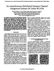
LD Photovoltaic system LN DPVM – Photovoltaic module ratings LN DPVA – Photovoltaic array characteristics LN DPVC – Photovoltaic array controller LN DTRC – Tracking controller LN XSWI – DC switch LN XCBR – Circuit breaker
...
LN ZINV – Inverter
LN MMXU – Electrical measurements
Figure 8. Logical Device for Photovoltaic System according to IEC 61850. Functions are represented as Logical Nodes. The hardware-specific parts needs the information when the axes shall be moved and when the gripper shall grip or release. This is achieved by the output-events. On the other side the hardware-specific FBs must indicate if the desired hardware-state is reached (for the gripper Gripped or Released, and for the axes which end-position is reached). Notice that no hardware-specific parameters are used in the adapters. Based on this minimal interface every kind of 2position-axis (e.g., electric, pneumatic, hydraulic) and every type of gripper (e.g., vacuum, 2-finger) can be used for the application given in Fig. 6. 5.2. Smart Energy Systems The second example is motivated by the energy domain. The important Smart Grid interoperability standard IEC 61850 [15] for power utility automation defines an abstract data and communication model, which can be mapped to several protocols. Electrical equipment components, line breakers, switches, etc. but also distributed energy resources (e.g., photovoltaic (PV) systems, fuel cells, wind turbines, biomass), are represented in the information model by so-called Logical Devices (LDs) (see Fig. 8). Control, protection, and measurement services of power utility components are usually encapsulated by Logical Nodes (LNs), which thereby form the building blocks of the LD. Typical LNs are basic equipment functions like measuring or switching functions, specialized functions (e.g., inverter, rectifier, battery charger), but also data relevant for engineering and operation (e.g., characteristics of PV modules). Each LN is composed of mandatory, optional, and conditional Data Objects (DOs). DOs in LNs are grouped into measured values, controls, metered values, status information, settings, and DOs without category [14]. If we compare the IEC 61850 structuring elements with the elements from the proposed approach we identify many similarities. The hierarchical structuring of IEC 61850 by LDs, LNs, and DOs is comparable to and feasible with the proposed approach. If we consider
the previous example (see Fig. 6) the same structure can in principle be used to represent IEC 61850-based systems, whereby the LD and LN would be equivalent to the hardware-independent FBs in the hierarchical structuring. The HandlingUnit-Sub-App is equivalent to a LD, the parts of it (axes and gripper) are equivalent to the LN. The hardware-specific Sub-Apps would be implemented by DOs. This can be carried out by implementing the hardware independent and dependent LN specifications with IEC 61499 FBs and using the adapter concept in order to achieve a maximum amount of reusability of the control logic.
6. Conclusion Reusable control logic is a key point for reducing the automation software development effort while at the same time increasing the quality of the overall automation system. A main issue of actual approaches is the intertwining of I/O access and control code, which usually leads to an early binding of control logic to hardware devices (i.e., sensors, actuators, controllers, etc.). In order to overcome these limitations we introduced the concept of ICPs. ICPs group a set of logically connected inputs and outputs together to one component (e.g., pneumatic axis, line breaker). By utilizing IEC 61499’s adapter concept the ICP interface can be clearly defined and easily used in control applications. Furthermore, it allows standardizing common ICPs and developing control applications independently of the used hardware modules. The implementation of the hardware specific process interface has to be adapted to the used hardware. Applying the MDA method, this approach leads to the advantage that it can provide both control specific as well as hardware specific parts automatically. The developed concept was applied to two test examples to evaluate its applicability: a pick and place unit and to a photovoltaic system. It has been shown that the application is structured in a much clearer way and features a well defined interface to the used hardware. Furthermore, the concept improves the commissioning and maintenance of systems as it eases the switching to different hardware devices. It also allows an easier switching to ICPs that attach the control application to a simulation of the plant, which greatly reduces the effort for virtual commissioning of industrial automation and control systems. The analysis and evaluation provided in this paper shows therefore that the ICP concept together with the adapter concept greatly improves the control application design and implementation. This usually leads to better structured and more reusable control software.
Acknowledgments This work has been supported by the Austrian Research Promotion Agency (FFG) project MASGrid (832037) under the Research Studios Austria program. The re-
search leading to these results has received funding from the European Union’s Seventh Framework Programme (FP7/2007-2013) under grant agreement n◦ 284573.
References [1] J. Bezivin and O. Gerbe. Towards a precise definition of the OMG/MDA framework. In Automated Software Engineering, 2001. (ASE 2001). Proceedings. 16th Annual Int. Conf. on, pages 273 – 280, Nov. 2001. [2] J. H. Christensen. HOLOBLOC.com - Function BlockBased, Holonic Systems Technology, Access: 06/2012. [3] G. Doukas and K. Thramboulidis. A Real-Time-LinuxBased Framework for Model-Driven Engineering in Control and Automation. IEEE Trans. Ind. Electron., 58(3):914–924, March 2011. [4] G. Ebenhofer, M. Rooker, and S. Falsig. Generic and reconfigurable IEC 61499 function blocks for advanced platform independent engineering. In Proc. of 9th IEEE Int. Conf. Ind. Informatics (INDIN), pages 591–596, 2011. [5] C. Gerber and H.-M. Hanisch. Does portability of IEC 61499 mean that once programmed control software runs everywhere? In Proc. of 10th IFAC Workshop on Intelligent Manufacturing Systems, pages 29 – 34, 2010. [6] R. Hametner, B. Kormann, B. Vogel-Heuser, D. Winkler, and A. Zoitl. Test case generation approach for industrial automation systems. In Automation, Robotics and Applications (ICARA), 2011 5th Int. Conf. on, pages 57 –62, Dec. 2011. [7] D. H¨astbacka, T. Veps¨al¨ainen, and S. Kuikka. Modeldriven development of industrial process control applications. J. Syst. Software, 84(7):1100 – 1113, 2011. [8] I. Hegny, M. Wenger, and A. Zoitl. IEC 61499 based simulation framework for model-driven production systems development. In Emerging Technologies and Factory Automation (ETFA), 2010 IEEE Conf. on, pages 1 –8, Sept. 2010. [9] I. Hegny and A. Zoitl. Component-based simulation framework for production systems. In Industrial Technology (ICIT), 2010 IEEE Int. Conf. on, pages 1020 –1025, March 2010. [10] I. Hegny, A. Zoitl, and W. Lepuschitz. Integration of simulation in the development process of distributed IEC 61499 control applications. In Industrial Technology (ICIT), 2009 IEEE Int. Conf. on, pages 1–6, Feb. 2009. [11] N. Higgins, V. Vyatkin, N.-K. Nair, and K. Schwarz. Distributed Power System Automation With IEC 61850, IEC 61499, and Intelligent Control. IEEE Trans. Syst., Man, Cybern. C, Appl. Rev., 41(1):81–92, Jan. 2011. [12] IEC SC65B. IEC 61131-3 – Programmable Controllers – Part 3: Programming languages. IEC, Geneva, 2003. [13] IEC SC65B. IEC 61499: Function blocks for industrialprocess measurement and control systems – Part 1: Architecture. IEC, Geneva, 2005. [14] IEC TC57. IEC/TR 61850-7-420: Communication networks and systems for power utility automation – Part 7420: Basic communication structure – Distributed energy resources logical nodes. IEC, Geneva, 2009. [15] IEC TC57. IEC 61850: Communication networks and systems for power utility automation. IEC, Geneva,, 2010. [16] C. Landsteiner, F. Andren, and T. Strasser. Evaluation and test environment for automation concepts in Smart Grids applications. In Proc. IEEE First Int. Smart Grid Modeling and Simulation (SGMS) Workshop, pages 67–72, 2011.
[17] R. Lewis. Modeling Control Systems Using IEC 61499 - Applying Function Blocks to Distributed Systems. The Institution of Electrical Engineers, London, 2001. [18] S. J. Mellor, S. Kendall, A. Uhl, and D. Weise. MDA Distilled. Addison Wesley Longman Publishing Co., Inc., Redwood City, CA, USA, 2004. [19] nxtControl. NXTControl.com - nxt generation software for nxt generation customers, Access: 06/2012. [20] J. Poole. Model-driven architecture: Vision, standards and emerging technologies. In Workshop on Metamodeling and Adaptive Object Models, ECOOP, 2001. [21] J. Siegel. Developing in OMG’s New Model-Driven Architecture. Management, 2001. [22] T. Strasser, C. S¨under, and A. Valentini. Model-driven embedded systems design environment for the industrial automation sector. In Ind. Informatics (INDIN), 2008. 6th IEEE Int. Conf. on, pages 1120 –1125, July 2008. [23] C. Szyperski. Component Software: Beyond ObjectOriented Programming. ACM Press, New York, 2 edition, 2002. [24] K. Thramboulidis. Development of distributed industrial control applications: the CORFU framework. In Factory Communication Systems, 2002. 4th IEEE Int. Workshop on, pages 39 – 46, 2002. [25] K. Thramboulidis. Model-integrated mechatronics - toward a new paradigm in the development of manufacturing systems. IEEE Trans Ind. Informat., 1(1):54 – 61, Feb. 2005. [26] V. Vyatkin. The IEC 61499 standard and its semantics. IEEE Ind. Electron. Mag., 3(4):40 –48, Dec. 2009. [27] V. Vyatkin. IEC 61499 as Enabler of Distributed and Intelligent Automation: State-of-the-Art Review. IEEE Trans Ind. Informat., 7(4):768 –781, Nov. 2011. [28] F. Wagner, J. Bohl, and G. Frey. An IEC 61499 interpretation and implementation focused on usability. In Emerging Technologies and Factory Automation (ETFA), 2008. IEEE Int. Conf. on, pages 184 –191, Sept. 2008. [29] M. Wenger, R. Hametner, A. Zoitl, and A. Voigt. Industrial embedded model predictive controller platform. In Emerging Technologies Factory Automation (ETFA), 2011 IEEE 16th Conf. on, pages 1–4, Sept. 2011. [30] M. Wenger, M. Melik-Merkumians, I. Hegny, R. Hametner, and A. Zoitl. Utilizing IEC 61499 in an MDA control application development approach. In Automation Science and Engineering (CASE), 2011 IEEE Conf. on, pages 495 –500, Aug. 2011. [31] G. Zhabelova and V. Vyatkin. Multiagent Smart Grid Automation Architecture Based on IEC 61850/61499 Intelligent Logical Nodes. IEEE Trans. Ind. Electron., 59(5):2351 –2362, May 2012. [32] L. Zhu, D. Shi, and X. Duan. Standard Function Blocks for Flexible IED in IEC 61850-Based Substation Automation. IEEE Trans. Power Del., 26(2):1101–1110, April 2011. [33] A. Zoitl and H. Prahofer. Building hierarchical automation solutions in the IEC 61499 modeling language. In Ind. Informatics (INDIN), 2011 9th IEEE Int. Conf. on, pages 557 –564, July 2011. [34] A. Zoitl and V. Vyatkin. IEC 61499 Architecture for Distributed Automation: The ”Glass Half Full” View. IEEE Ind. Electron. Mag., 3(4):7 – 23, 2009.