Towards an Integration of Standard Component-Based Safety Evaluation Techniques with SaveCCM Lars Grunske School of Information Technology and Electrical Engineering ARC Centre for Complex Systems, University of Queensland, 4072 Brisbane (St.Lucia), Australia
[email protected]
Abstract. To deliver complex functionalities in a cost effective manner, embedded software should ideally be developed with standardized interoperable components. At the same time, most of these embedded systems must be demonstrably safe and reliable. This paper aims to extend SaveCCM, a modelling language for component-based embedded systems, with standard safety evaluation models. Based on this extension, failure and hazard probabilities can be estimated early in the development process and can be used to check if a system can fulfil its safety requirements. The procedure of the safety evaluation is demonstrated with the case study of a computer assisted braking system.
1 Introduction Modern safety-critical real-time systems in various application domains, such as automotive, avionic, defence and medical systems, are becoming increasingly complex ensembles of hardware and software components. Design and development of these complex component-based systems including their architectures is challenging, because systems and software engineers need to deal with strict non-functional requirements, such as safety, availability, reliability, performance, memory consumption and real-time requirements [1, 2], while keeping development and life-cycle costs low and practicable. Therefore, component-based software engineering technologies in these domains must be capable of predicting dependability attributes of a system assembled from components. Currently, several component-based modelling languages and component frameworks aim to solve this problem. Examples are the PECT (Predictionenabled Component Technology) [3] initiative of the Software Engineering Institute at the Carnegie Mellon University, the Ptolemy II project [4] of the University of California at Berkeley and the KOALA component model [5], which is used at Philips for embedded software in consumer electronic devices. This paper focuses on SaveComp [6]; a recent component-based development framework for embedded control applications in automotive (vehicular) systems. This framework is based on a control flow paradigm and its basic aim is to create predictable component-based systems. The underlying formalism for the construction of SaveComp systems is the architecture description language SaveCCM (SaveComp Component Model). This language has a simple graphical syntax [6] and a formal semantics [7],
which uses the theory of timed automata [8]. Based on this semantics, system properties can be checked with the UPPAAL [9] model checker. Other prediction techniques [6, 10] provide the ability to predict Worst-Case Execution Time (WCET) of components, Worst Case Response Time (WCRT) of an assembled system or resource utilization of a set of components. The early prediction of these correctness and real-time properties allows reducing the number of design failures in the software system. These design failures are also known as systematic failures, because they systematically occur during runtime, if the system is operated with a certain sequence of input requests. However, for a complete safety analysis, additionally random and wear-out failures of the hardware elements have to be considered. These failures occur stochastically distributed over the mission time of the system and they are generally quantified with probabilistic metrics [11], such as failure rates (λ), Mean Time To Failure (M T T F ) or Mean Time Between Failures (M T BF ). To facilitate a quantitative safety analysis of component-based systems, encapsulated evaluation models, such as Component Fault Trees (CFT) [12] or State-Event Fault Trees (SEFT) [13] have been developed. Generally, an encapsulated evaluation model specifies all necessary information to reason about quality attributes independently from the deployment context and the environment of an architectural entity. In the case of safety evaluation, these encapsulated evaluation models describe possible failures of component services and enable the estimation of their failure probabilities. The overall goal of this paper is to identify if these models can be integrated within the SaveComp modelling framework. In detail, the contributions of this paper are as follows: – Identify a suitable formalism for safety evaluation (failure specification and analysis) within SaveCCM – Create a methodology to systematically generate safety evaluation models – Validate the methodology with a complex case study – Identify the limitation of this approach and proposed future research directions to overcome these limitations This rest of this paper is structured as follows. Section 2 reviews related work and describes state-of-the-art techniques in the area of safety evaluation for componentbased systems. The basic concepts of SaveCCM are introduced in Section 3. An integration of the standard safety evaluation techniques and SaveCCM is presented in Sections 4 and 5. The general aim of these sections is to describe how probabilistic failures can be specified and how failure propagation models can be generated. The presented approach will be validated in Section 6 with the case study of a computer assisted braking system. Finally, conclusions as well as relevant directions for future work are given in Section 7.
2 Related Work The related work can be distinguished into two categories. The first category contains analysis techniques for quality attributes, which are preliminaries for safety evaluation and which have been already integrated with SaveCCM. The second category contains
detailed approaches for safety evaluation for other component-based specification languages. Within SaveCCM, as already mentioned in the introduction, prediction techniques for real-time and resource consumption properties [6, 10] have been integrated. The prediction of both properties is needed as a prerequisite for a complete safety evaluation. An approach that focuses on correctness and robustness of component-based specifications (with a focus on SaveCCM) is described by Elmqvist, Nadjm-Tehrani and Minea [14]. This approach reasons about these two safety-relevant properties with a formalism called safety interfaces. A safety interface describes the capability of components to provide correct behavior in an environment in the presence of single or multiple faults. The interesting innovation of this work is that these safety interfaces can be automatically generated for a specific safety property. The generation algorithm uses component behavior specification based on reactive modules [15] and a model checking technique that is similar to the counter example driven abstraction-refinement (CEDAR) principle [16]. More specifically in this approach, the ideal environment is weakened until the most restrictive environment in terms of environment failures is found, under which the component still fulfils the system level safety property. If this technique can be extended to allow the automatic generation of probabilistic safety interfaces, an integration into the approach presented in this paper seems to be very promising and could be beneficial for both approaches. A major research stream on safety evaluation of general component-based software architectures is nowadays directed towards creating encapsulated failure propagation models [12, 13, 17–19]. These failure propagation models describe how failure modes of incoming messages (input failure) together with internal component faults propagate to failure modes of outgoing messages (output failure). The first notation that promotes these failure propagation models is the Failure Propagation Transformation Notation (FPTN) [17]. Other relevant notations are the Tabular Failure Annotations (TFA) in the context of the Hierarchically Performed Hazard Origin and Propagation Studies (HiP-HOPS) methodology [19] and Component Fault Trees (CFT) [18]. For specific component-based specification languages, these two newer models allow a tool-supported and automated generation of the safety evaluation model. This automation is needed for a successful technology transfer to industrial practise, since manually performed safety analysis techniques are error-prone or even infeasible for complex component-based systems. Examples for supported component-based specification languages are Matlab-Simulink models in the case of HiPHOPS [20] and ROOM models annotated with Interface Automata in the case of CFTs [21]. A limitation of each of the current failure propagation models is their inability to handle cyclic data- and controlflow structures in the system architecture. This is a major drawback of these techniques as many real-world control systems contain closed feedback loops. To overcome this problem, Wallace introduces in [22] his Fault Propagation and Transformation Calculus (FPTC). This calculus solves the problem of cyclic dependencies in the failure propagation model by using fixed-point evaluation techniques. However, the practicability of this calculus in industrial case studies remains to be proven. From a high-level viewpoint, all four encapsulated failure propagation models (TFA, FPTN, CFT and FPTC) have a similar expressiveness and an identical conceptual foun-
dation [12]. The only differences can be identified in the tool support, representation (graphical vs. textual) and methodological support. Consequently, for this research it does not matter which of these failure propagation models is used, as the result of this research can also be transferred to another model.
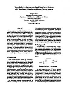
3 Description of SaveCCM SaveCCM describes the architecture of a system with three basic syntactical elements [6]: Components, Switches and Assemblies. Components are the basic elementary units. They cannot be decomposed any further and contain a behavior specification that describes the functionality of a component in the SaveComp execution framework [6, 7]. Switches provide facilities to dynamically change component interconnection structures between the Components. Consequently, they allow a reconfiguration of the system at runtime. Finally, Assemblies are used as building blocks for complex systems. They can contain Components and Switches as well as other Assemblies and specify how these elements must be connected. Each of the three syntactical elements are graphically represented by a box which contains the name of the component and a stereo type which specifies the element type (hhSaveCompii, hhSwitchii or hhAssemblyii).
Fig. 1. Syntax Elements of SaveCCM
The interaction of SaveCCM elements with their environment is only allowed via well-defined interface elements called ports. Two basic types of ports are distinguished in SaveCCM: Input Ports and Output Ports. Ports are further distinguished by the information they allow to send or receive. More specifically in SaveCCM the following port subtypes can be specified: (a) Data Ports, (b) Trigger Ports and (c) Data and Trigger Ports. Data Ports, which are also named as Data Only Ports in [6], are one-element buffers of a pre-specified datatype (e.g. Boolean, Integer, Real, String etc.). This therefore enables a Data Output Port to write an element of the specified type to the buffer
whilst a Data Input Port is able to read and consume this particular data element. Since the buffer can contain only one element, each additional write operation of the Data Ouput Port will overwrite its last value. Trigger Ports, or Trigger Only Ports [6], are used for controlling the activation of a Component. Semantically, Trigger Ports are described by a Boolean variable, which is set to TRUE in order to activate a component. If a component contains more than one Input Trigger Ports each of these Input Trigger Ports mmust be activated in order to activate the component. Data and Trigger Ports combine the features of both previously described port types. Finally, to connect external ports of assemblies with corresponding ports of internal elements another syntax element is required. This syntax element is called Delegation and can only be used to connect input or output ports of an assembly with input or output ports of the same type of internal elements. Each of the syntax elements is represented in a UML 2.0 like graphical notation. The graphical symbols of this notation are given in Figure 1.
4 Specification of Encapsulated Failure Propagation Model within SaveComp To integrate encapsulated failure propagation models [12, 13, 17–19] with the SaveComp development framework, SaveCCM elements (Switches and Components) have to be annotated with failure propagation specifications. An annotation of SaveCCM Assemblies is not necessary, because they are just a purely syntactic concept that provides a name for a collection of components, and restricts the way in which they can be connected to components outside the assembly. Consequently, they do not influence the semantic and emergence of failures at all. Within the SaveComp development framework, failure propagation specifications should describe the emergence of incorrect behavior (failures) and the propagation and transformation of failures. For safety evaluation, specifically output failures have to be analyzed. These output failures logically depend on either internal faults or input failures that are caused by the environment of a SaveCCM element. Since SaveCCM components, switches and assemblies have well-defined interfaces and are strongly encapsulated, we assume that output failures can only be observed at the output ports. Similarly, input failures can only occur at input ports. This restricts the complexity of the failure propagation specification. However, the number of failures, which can occur at an input port or can be observed at an output port, are either very large or even infinite. To reduce the number failure propagation models, an accepted categorization is used [23] to classify each failure into one of the following failure types: – v: value failure (wrong data or service result) – te: timing failure - too early (event or service is delivered before it was expected) – tl: timing failure - too late (expected event or service is delivered after the defined deadline has expired) – o: omission (no event or service is delivered when it is expected) – c: commission (unexpected event or service)
Within the SaveCCM modelling framework, value failures can only occur at Data Ports and Trigger and Data Ports. Timing failures as well as omission and commission failures can only be associated to Trigger Ports and Trigger and Data Ports. To explain the specification of failure propagation models a triggered 2-bit full adder component specified as a SaveCCM component (Figure 2) will be used in the following as an example. This component provides an incorrect value at the Output Data Port O if one of the two Input Data Ports I1 , I2 or the ”carry in” port Cin receives a wrong value (I1 .v, I2 .v or Cin .v) or if this component has an internal design fault I nternalF ault. Furthermore, timing, omission or commission failures of the Trigger Port T may lead also to a failure. For example they result in a wrong value at the output of the adder, in cases of an early trigger (Tin .te), Fig. 2: SaveCCM Compobecause the correct values of the Input Ports has not been nent: 2 Bit Full Adder written to the buffer or if there is a delay in the trigger (Tin .tl) the values of the Input Ports may have be overwritten by newer values. In case of a trigger omission (Tin .o) the value at the output buffer is still the value of the last calculation and if the trigger occurs unexpectedly (Tin .c), then the correct value of the Output Buffer may become overwritten by newer results. As a result, a value failure of the Data Output Port O must be described by the following failure propagation model which contains only disjunctions: O.v= I1 .v ∨ I2 .v ∨ Cin .v ∨ InternalF ault ∨ Tin .te ∨ Tin .tl ∨ Tin .o ∨ Tin .c For a complete specification of the failure propagation model for the 2-bit adder a similar logical formula has to be created for possible failures of the Output Ports Cout and Tout . If for all internal faults and input failures probabilistic measures, like failure rates or failure probabilities, are available then the probability of an output failure can be determined by a basic fault tree analysis. However, the assumption must hold that all the input failures and internal faults are stochastically independent.
5 Safety Analysis within SaveCCM In the previous section, basic concepts to allow the specification of failure propagation models within the SaveComp development framework where given. To be applicable to complex specifications methodological support is needed that guides safety analysts (a) to create an encapsulated failure propagation model for each elementary component in the system and (b) to use these encapsulated evaluation models to check if a system built with these components could fulfil its safety requirements. To provide this methodological support, first, a basic process model is introduced, which explains the basic tasks that are needed to perform a structured hazard analysis within the SaveComp framework. Secondly, each of the required steps of this process are explained and techniques and tools are presented that can be used to guide these tasks. 5.1 Basic Process Model A safety analysis process with failure propagation models can be generally structured into three phases [13, 24]. For the safety evaluation of SaveCCM architectures, in the
first phase an encapsulated failure propagation model has to be constructed for each SaveCCM Component and Switch. This task must be performed by the component developer or by the component supplier. To generate an encapsulated failure propagation model for a SaveCCM Component or Switch a HAZOPS (HAZard and OPerability Studies)-based technique called SHARD (Software Hazard Analysis and Resolution in Design) [25] can be used. SHARD has been especially designed to handle software and hardware components and its procedure is described in section 5.2. In the second phase, a fault propagation model must be constructed for the entire architecture. To perform this task SaveCCM Assemblies are investigated and a failure propagation model needs to be constructed recursively according to the hierarchical structure of these Assemblies. In the final phase, the fulfilment of the safety requirements needs to be verified based on the complete failure propagation model of the system. A safety requirement is a (more or less formal) description of a hazard combined with the tolerable probability of this hazard [12]. In control systems, a hazard can be caused by single or multiple failures. Consequently, the first task is to identify which output failures of the failure propagation model lead to which hazards and what is the logical relation between output failures and hazards. As a technique to perform this task, again SHARD can be used. The next task is to calculate probabilities of output failures by analyzing the systemlevel failure propagation model. Then, based on the logical relations between output failures and hazards, hazard probabilities can be calculated. Both tasks are computationally expensive and should be performed by a suitable tool (e.g. HiPHOPS [19] or ESSaReL [26]). Finally, the safety engineer must check if the probability of a hazard is lower than its tolerable hazard probability. If the probability is lower than the tolerable hazard probability, then the architecture specification fulfils its safety requirements. If not, the architecture must be revised and additional safety mechanisms (e.g. watchdogs or redundancy) should be included. To summarize, the inputs for a safety evaluation are: (a) the SaveCCM specification, which describes the architecture of the system, (b) a failure propagation model for each element of the SaveCCM specification and (c) a list of relevant hazards and its tolerable hazards probabilities. The necessary steps are: 1. Generate an encapsulated failure propagation model for each SaveCCM Component and Switch. 2. Identify the relations between system output failures and hazards. 3. Construct an encapsulated failure propagation model for each SaveCCM Assembly. 4. Calculate the output failure probabilities of the system-level Assembly and accordingly the hazard probabilities of the system. 5. Compare the calculated hazard probabilities with the tolerable hazard probabilities. 5.2 Applying SHARD for Identifying Fault Propagation Models of SaveCCM Components and Switches SHARD, as proposed in [25], is a structured design assessment to identify potentially hazardous behavior in software systems. SHARD is a team-based approach that focuses on the information flows between software components in a system. Each information
flow is sequentially investigated with the set of guidewords for failure propagation models to prompt consideration of possible deviations from the intended behavior. For each deviation considered, the team must determine all plausible causes in terms of input failures and internal faults. Additionally, in a complete SHARD analysis safety engineers need to determine whether a deviation can contribute to system-level hazards and they must propose resolutions. O.v Cout .v Tout .tl Tout .te Tout .o Tout .c For the generation of failure propagation models of SaveCCM I1 .v ✘ ✘ Components and Switches, the last I2 .v ✘ ✘ two tasks are not required and Cin .v ✘ ✘ furthermore these activities cannot T .tl ✘ ✘ ✘ ✘ in be performed for a single compo- T .te ✘ ✘ ✘ in nent without considering the sys- T .o ✘ ✘ ✘ ✘ in tem context. Due to this, the main T .c ✘ ✘ ✘ in activity for the generation of fault Table 1: SHARD table for 2-bit full adder propagation models is to sequentially investigate each outgoing information flow and to identify possible causes in terms of input failures and internal faults. Note that the possible deviations (te, tl, v, o and c) of an information flow within the SaveComp framework are restricted by the type of the SaveCCM port (Data vs Trigger ports), which simplifies the analysis. The results of the investigation should be documented in a table, where the columns show possible deviations of outgoing information flows (consequences) and the rows represent deviations of the input information flows or internal faults (causes). A ✘ in a cell (x,y) of this table means that if cause y occurs then a possible result could be consequence x. An example of such a table is presented in Table 1 for the 2-bit full adder component introduced in Section 4. To improve the results, the investigation should also be performed in the opposite direction, from causes to consequences [27]. This will result in a deeper understanding of the SaveCCM Components and Switches and completes the cause-consequence matrix. The final task is to create a failure propagation model based on the SHARD table. In this task, basically, a logical formula must be identified that represents the relations between an outgoing failure of a component and its causes. To do so, each column in the SHARD table has to be investigated and each cause marked with a ✘ must be logically related to the outgoing failure. The most common logical relations are AND and OR relations. An OR relation means that each one of the causes can lead to the output failure. In case of an AND relation, all causes must occur to cause the consequence. The overall semantics is identical to the fault tree logic [28]. 5.3 SHARD to identify relevant system level failures that can cause a hazard Similar to the procedure of SHARD at the component level (SaveCCM Components and Switches), SHARD could be also applied at the system level. The goal of this application is to investigate the relationships between system level failures (deviation of the outgoing failure flows) and hazards that can cause harm to the environment [29]. The results of the system-level SHARD should also be documented in a table. In this
table columns represent hazard conditions, rows represent deviations of outgoing information flows and a ✘ indicates a possible relationship. An example of such a table is given in Section 6 in Table 2 for relations between hazards and system level failures for the case study of a computer assisted braking system. Based on the SHARD table the logical relationships between the hazards and the system level failures must be identified. These logical relationships become the toplevel formulas for the safety evaluation model that must be entered in the evaluation tool as described in [12]. 5.4 Constructing Fault Propagation Models for SaveCCM Assemblies To construct failure propagation models for SaveCCM Assemblies all embedded SaveCCM elements must be first annotated with a failure propagation model. Then each possible failure propagation between these embedded elements must be identified. Since SaveCCM elements are strongly encapsulated, we assume that these failure propagations can only occur via connections of output and input ports. As a result of this assumption, the following two cases need to be distinguished: (a) the failure propagation within the assembly between two embedded SaveCCM elements and (b) the failure propagation between the environment (input and output ports of the assembly) and an internal component/switch/assembly. To resolve the failure propagation between two embedded SaveCCM elements the associated failure types of the input port need to be substituted with corresponding failure propagation formulae of the output port. This substitution is also the reason why fault propagation models and the corresponding data and control flow architecture must be acyclic, because in case of a cycle this substitution will not terminate. To resolve the failure propagation between the environment and internal components a renaming is needed that renames failure flows according to the input and output port of the assembly.
Fig. 3. 3-Bit-Adder SaveCCM-Assembly
To explain this procedure, we will assume a 3-bit adder Assembly, which uses a series connection of two 2-bit adder (Figure 2). In this assembly, the output ports O1 , 1 1 2 and Cout and Tout of the first 2-bit adder are connected to the input ports I22 , Cin 2 Tin of the second 2-bit adder. Note, the superscripts denote the instance of the 2-bit adder (first vs. second). All other ports are delegated to external ports of the 3-bit adder (I1 ,I2 ,I3 ,O,Tin and Tout ). In this example, we will focus on the value failure of the data output port O of the 3-bit adder which depends on the output of the second 2-bit adder. Consequently, the failure propagation formula O2 .v for the 2-bit adder as described in section 4 must be used as a starting point. Then each failure that is related to an output of the first 2-bit adder needs to be substituted by the corresponding failure propagation formulae. The failure propagation model after the substitution of the value failure of the input port I22 are as follows: ¢ ¡ 1 1 1 1 1 .c .te∨ Tin .tl∨ Tin .o∨ Tin .v∨ InternalF ault1 ∨ Tin O.v = I12 .v∨ I11 .v∨ I21 .v∨ Cin 2 2 2 2 2 .c. .o ∨ Tin .v ∨ InternalF ault2 ∨ Tin .te ∨ Tin .tl ∨ Tin ∨Cin Similar to the substitution of the failure flows of the input port I22 , the failure flows of 2 the input ports C 2 and Tin need to be substituted. Finally, the internal input port names need to be substituted with the input port names of the assembly, to describe the failure propagation between the environment and internal components. Consequently, based on the SaveCCM Delegations in the model of the 3-bit adder the following renaming 1 → Tin . should be applied: I11 → I1 , I21 → I2 , I12 → I3 , C 1 → C and Tin
6 Case Study
To explain the presented approach in more detail a computer assisted braking system is chosen as an example case study [30]. Variations of this system are currently used in most modern cars to enhance their braking performance. A complete description of the system including its components can be found in [29, 31, 30]. In addition to traditional hydraulic brakes the computer assisted braking system adds the following new functions: anti (b)lock braking, emergency stop detection and enhancement and load balancing of the four brakes corresponding to the road and driving condition. The anti (b)lock braking function (ABS) is used to prevent skidding and help drivers maintain steering control on wet and slippery roads. The Emergency Stop Detection function automatically maximizes the brake pressure if it detects any sudden pedal movement associated with an emergency stop. The load balancing function aims to improve the braking performance by compensating uneven braking due to heavy or unbalanced loading of the vehicle. A failure in any of the three functions could lead to serious accidents. Consequently, there is a need to prove that the system fulfils the safety requirements that have been identified in a preliminary hazard analysis [30]. These safety requirements are summarized in Figure 4.
Hazard ID H1 H2 H3 H4 H5 H6 H7
Effect Description
Risk Class
Complete lack of braking Lock up (1–4 wheels) Unexpected application/release of the brakes Braking response not proportional to demand Tardy/slow response Uneven braking (pressures vary “wildly” in response to constant demand) Unequal braking (1-3 wheels brake less or more than required)
Catastrophic Catastrophic Catastrophic Catastrophic Major Major Major
Tolerable Hazard Rate (THR) (per hour) 10−8 10−8 10−8 10−8 10−7 10−7 10−7
Fig. 4. Results of the PHA for the computer assisted braking system [30]
Fig. 5. SaveCCM architecture of the computer assisted braking system
System Hazardous Failure Modes The SaveCCM architecture for the sysOutput H1 H2 H3 H4 H5 H6 H7 tem is given in Figure 5. To meet the timing requirements of a 20 ms latency from BrakeData.o ✘ ✘ ✘ ✘ BrakeData.c ✘ ✘ ✘ ✘ brake pedal movement to brake effect, a 10 ms period (100Hz) has been selected for the BrakeData.te ✘ ✘ main tasks [30]. Please note that the sensors BrakeData.tl ✘ ✘ (ALS,BPS and WRS) in the architecture have BrakeData.v ✘ ✘ ✘ ✘ no trigger input ports, consequently they do Table 2: Effect of failures of the Brake not get activated and hence they are not com- Data Output on Hazardous Failure Modes plete SaveCCM Components. However, in this H1-H7 [29] case study, we assume that these sensors are electronic units that continuously provide the required information. To perform the safety evaluation a SHARD has been performed for each component in the system. An example of a resulting SHARD table is presented in Table 3. Additionally, in [29], SHARD has also been applied to identify the relationships between system hazards and system-level failures (cp. Table 2).
SaveCCM Component Emergency Stop Detection
Output Failure Flow Brake (4 Wheels) Data ( B4WD ) B4WD.v B4WD.te B4WD.tl B4WD.o B4WD.c
bpa1.v ✘ bpa2.v ✘ t(100Hz).te ✘ t(100Hz).tl ✘ t(100Hz).o ✘ ✘ t(100Hz).c ✘ ✘ Internal timing problem ✘ ✘ ✘ ✘ (Int1) Wrong interpretation of the ✘ input data(Int2) Hardware failure of the un✘ ✘ ✘ ✘ derlying control unit(Int3) Memory problem in the ✘ data segment of the underlying control unit(Int4) Table 3. SHARD Table for the SaveCCM Component - Emergency Stop Detection [29]
Based on the SHARD tables, in the next step a fault propagation model has been generated for each component. As an example, the fault propagation model for the Emergency Stop Detection component looks as follows: – – – – –
B4WD.v =(bpa1 .v ∧ bpa1 .v ) ∨ Int2 ∨ Int4 B4WD.te=t (100Hz ) .te ∨ t (100Hz ) .c ∨ Int1 ∨ Int3 B4WD.tl =t (100Hz ) .tl ∨ t (100Hz ) .o ∨ Int1 ∨ Int3 B4WD.o = t (100Hz ) .o ∨ Int1 ∨ Int3 B4WD.c= t (100Hz ) .c ∨ Int1 ∨ Int3
All fault propagation models have been translated to component fault trees (CFTs) and have been modelled with the tool UWG, which was developed in the ESSaRel project [26]. UWG is an academic prototype for the specification and evaluation of CFTs which is currently also used in industrial projects. However, beside this tool support, one general problem in the construction of analyzable fault propagation models such as CFTs is to identify the failure probabilities of the internal faults [32]. In this case study, a failure rate of 10−8 per hour has been assumed for all software-base failures. This assumption is based on the fact that the software must be developed with rigorous software development methods to comply with safety integrity level (SIL) four [33]. The failure rates of hardware-based failures have been taken from the specifications published in [29]. Based on the component fault trees and the internal fault probabilities the probabilities of safety critical failures of the system has been determined. To repeat this evaluation, the complete model can be downloaded from the author’s web-page (http://www.itee.uq.edu.au/ grunske/ QOSA2006/cabs.uw3). The results of this evaluation clearly indicate that the initial design does not fulfill the safety requirements. This
result is not unexpected since the initial design does not include any safety or reliability improving concepts (e.g. redundancy or watchdogs). Better designs for this case study are described in [29, 31].
7 Conclusion and Future Work To evaluate safety characteristics of SaveCCM specifications, this paper proposes an integration of failure propagation models with the SaveComp modelling framework. For this purpose each SaveCCM element has to be annotated with a failure propagation model that describes how failure modes of incoming messages (input failure) together with internal faults of the components propagate to failure modes of outgoing messages (output failure). Consequently, these failure propagation models describe the emergence of incorrect behavior independent from the component’s environment. If each SaveCCM element is annotated with a fault propagation model, a fault propagation model can be constructed for a complete SaveCCM specification. Based on this system-level failure propagation model and an operational profile, that quantifies call and failure probabilities of the system’s environment, probabilities of system output failures can be calculated. These system output failures can be related to system hazards and their probabilities can be calculated too. If all hazard probabilities are lower than their tolerable hazard probabilities then the SaveCCM specification fulfils its safety requirements. If not, quality improving transformations need to be performed [34]. The described method is still an early attempt for safety evaluation of SaveCCM specification and it has some major limitations and drawbacks. First, as mentioned in the related work section the fault propagation models must be acyclic. Consequently, the approach isn’t applicable to systems with cyclic data and control flow dependencies (e.g. control systems with closed feedback loops). Second, to obtain correct results the internal failure modes must be stochastically independent. To assure this a common cause failure analysis should be performed based on system-level fault propagation model. Third, the generation of fault propagation models for SaveCCM Components and Switches is currently based on expert knowledge and a team-based assessment with SHARD. An automated approach to generate these fault propagation models seems currently hard to achieve, but could increase the acceptance of the method significantly. Fourth and finally, the estimation of failure probabilities for systematic faults (e.g. design faults) is generally a hard task for software-based systems [11, 32]. To conclude this paper, there are some general problems that should be solved for a successful technology transfer to industrial practice. However, these problems are not specifically related to SaveCCM. Moreover, the results presented in this paper are very promising and have shown that a safety evaluation of SaveCCM models is possible and benefits from the clear and elegant syntax of the specification language.
References 1. Laprie(ed), J.C.: Dependability: basic concepts and terminology. Springer Verlag (1992) 2. Lee, E.A.: 2. In: Embedded Software. Volume 56. Advances in Computers, Academic Press, London (2002) 56–97
3. Hissam, S.A., Moreno, G.A., Stafford, J.A., Wallnau, K.C.: Packaging Predictable Assembly. In Bishop, J.M., ed.: Component Deployment, IFIP/ACM Working Conference, CD 2002, Berlin, Germany, June 20-21, 2002, Proceedings. Volume 2370 of Lecture Notes in Computer Science., Springer (2002) 108–124 4. PtolemyII : PtolemyII project website: http:// ptolemy.eecs.berkeley.edu/ ptolemyII/ (2006) 5. van Ommering, R., van der Linden, F., Jeff, K., Magee, J.: The Koala component model for consumer electronics software. Computer 33 (2000) 78–85 ˚ 6. Hansson, H., Akerholm, M., Crnkovic, I., T¨orngren, M.: SaveCCM - A component model for safety-critical real-time systems. In: 30th EUROMICRO Conference 2004, 31 August 3 September 2004, Rennes, France, IEEE Computer Society (2004) 627–635 7. Carlson, J., H˚akansson, J., Pettersson, P.: SaveCCM: An analysable component model for real-time systems. In: International Workshop on Formal Aspects of Component Software, Macao, Elsevier (2005) 8. Alur, R.: A theory of timed automata. Theoretical Computer Science 126 (1994) 183–235 9. Larsen, K.G., Pettersson, P., Yi, W.: UPPAAL in a nutshell. International Journal on Software Tools for Technology Transfer 1 (1997) 134–152 10. M¨oller, A., Peake, I., Nolin, M., Fredriksson, J., Schmidt, H.: Component-based contextdependent hybrid property prediction. In: ERCIM - Workshop on Dependable Software Intensive Embedded systems, Porto, Portugal, ERCIM (2005) 11. Birolini, A.: Reliability Engineering: Theory and Practice. Third edn. Springer (1999) 12. Grunske, L., Kaiser, B., Reussner, R.H.: Specification and evaluation of safety properties in a component-based software engineering process. In: Embedded Software Development with Components -An Overview on Current Research Trends, Springer-Verlag (2005) 737–738 13. Grunske, L., Kaiser, B., Papadopoulos, Y.: Model-driven safety evaluation with state-eventbased component failure annotations. In Heineman, G.T., Crnkovic, I., Schmidt, H.W., Stafford, J.A., Szyperski, C.A., Wallnau, K.C., eds.: Component-Based Software Engineering, 8th International Symposium, CBSE 2005, St. Louis, MO, USA, May 14-15, 2005, Proceedings. (2005) 33–48 14. Elmqvist, J., Nadjm-Tehrani, S., Minea, M.: Safety interfaces for component-based systems. In Winther, R., Gran, B.A., Dahll, G., eds.: Computer Safety, Reliability, and Security, 24th International Conference, SAFECOMP 2005, Fredrikstad, Norway, September 28-30, 2005, Proceedings. Volume 3688 of Lecture Notes in Computer Science., Springer (2005) 246–260 15. Alur, R., Henzinger, T.A.: Reactive modules. Formal Methods in System Design: An International Journal 15 (1999) 7–48 16. Clarke, E.M., Grumberg, O., Jha, S., Lu, Y., Veith, H.: Counterexample-guided abstraction refinement. In: Computer Aided Verification. (2000) 154–169 17. Fenelon, P., McDermid, J., Nicholson, M., Pumfrey., D.J.: Towards integrated safety analysis and design. ACM Computing Reviews, 2 (1994) 21–32 18. Kaiser, B., Liggesmeyer, P., M¨ackel, O.: A new component concept for fault trees. In: Proceedings of the 8th Australian Workshop on Safety Critical Systems and Software (SCS’03), Adelaide (2003) 37–46 19. Papadopoulos, Y., McDermid, J.A., Sasse, R., Heiner, G.: Analysis and synthesis of the behaviour of complex programmable electronic systems in conditions of failure. Int. Journal of Reliability Engineering and System Safety 71 (2001) 229–247 20. Papadopoulos, Y., Maruhn, M.: Model-based synthesis of fault trees from matlab-simulink models. In: 2001 International Conference on Dependable Systems and Networks (DSN 2001) (formerly: FTCS), 1-4 July 2001, G¨oteborg, Sweden, Proceedings, IEEE Computer Society (2001) 77–82
21. Grunske, L.: Annotation of component specifications with modular analysis models for safety properties. In: Proceedings of the 1st International Workshop on Component Engineering Methodology (WCEM), Erfurt (2003) 737–738 22. Wallace, M.: Modular architectural representation and analysis of fault propagation and transformation. Electr. Notes Theor. Comput. Sci. 141 (2005) 53–71 23. Bondavalli, A., Simoncini, L.: Failure Classification with respect to Detection. Esprit Project Nr 3092 (PDCS: Predictably Dependable Computing Systems) (1990) 24. Grunske, L., Kaiser, B.: Automatic generation of analyzable failure propagation models from component-level failure annotations. In: Fifth International Conference on Quality Software (QSIC 2005), 19-20 September 2005, Melbourne, IEEE Computer Society (2005) 117–123 25. Pumfrey, D.J.: The Principled Design of Computer System Safety Analyses. PhD thesis, Department of Computer Science, University of York (1999) 26. ESSaRel: Embedded Systems Safety and Reliability Analyser, The ESSaRel Research Project,Homepage: http://www.essarel.de/index.html (2005) 27. Lutz, R.R.: Software engineering for safety: a roadmap. In: ICSE - Future of SE Track. (2000) 213–226 28. IEC 61025(International Electrotechnical Commission): Fault-Tree-Analysis (FTA) (1990) 29. Prasad, D.K.: Dependable Systems Intergration using Measurement Theory and Decision Analysis. PhD thesis, Department of Computer Science, University of York (1998) 30. David Pumfrey and Marc Nicholson: Hazard Analysis of a Computer Assisted Braking System, In Hazard Analysis Course for MSc in Safety Critical Systems (1996) 31. Nicholson, M.: Selecting a Topology for Safety-Critical Real-Time Control Systems. PhD thesis, Department of Computer Science, University of York (1998) 32. Musa, J.D., Iannino, A., Okumoto, K.: Software Reliability: Measurement, Prediction, Application. MacGraw-Hill (New York NY), ; ACM CR 8712-0965 (1987) 33. CENELEC (European Committee for Electro-technical Standardisation): CENELEC EN 50126: Railway Applications – the specification and demonstration of Reliability, Availability, Maintainability and Safety. CENELEC EN 50128: Railway Applications: Software for Railway Control and Protection Systems CENELEC, Brussels (2000) 34. Grunske, L.: Identifying ”good” architectural design alternatives with multi-objective optimization strategies. In Osterweil, L.J., Rombach, H.D., Soffa, M.L., eds.: 28th International Conference on Software Engineering (ICSE 2006), Shanghai, China, May 20-28, 2006, ACM (2006) 849–852