Oct 29, 2007 - tive context under concern, it comes into various forms (automatic or ...... This multi-label energy function is minimized using the swap algorithms [6, 7]. .... Indeed, even if from frame 19, the face does not move and therefore is ...
INSTITUT NATIONAL DE RECHERCHE EN INFORMATIQUE ET EN AUTOMATIQUE
Track and Cut: simultaneous tracking and segmentation of multiple objects with graph cuts
N° 6337 October 2007
apport de recherche
ISRN INRIA/RR--6337--FR+ENG
„ Themes COM et COG
ISSN 0249-6399
inria-00181865, version 3 - 29 Oct 2007
Aurélie Bugeau — Patrick Pérez
Track and Cut: simultaneous tracking and segmentation of multiple objects with graph cuts Aur´elie Bugeau , Patrick P´erez Th`emes COM et COG — Syst`emes communicants et Syst`emes cognitifs Projet Vista Rapport de recherche n° 6337 — October 2007 — 23 pages
Abstract: This paper presents a new method to both track and segment multiple objects in videos using min-cut/max-flow optimizations. We introduce objective functions that combine low-level pixelwise measures (color, motion), high-level observations obtained via an independent detection module, motion prediction and contrast-sensitive contextual regularization. One novelty is that external observations are used without adding any association step. The observations are image regions (pixel sets) that can be output by any kind of detector. The minimization of these cost functions simultaneously allows ”detection-before-track” tracking (track-to-observation assignment and automatic initialization of new tracks) and segmentation of tracked objects. When several tracked objects get mixed up by the detection module (e.g., single foreground detection mask for objects close to each other), a second stage of minimization allows the proper tracking and segmentation of these individual entities despite the observation confusion. Experiments on different type of sequences demonstrate the ability of the method to detect, track and precisely segment persons as they enter and traverse the field of view, even in cases of partial occlusions, temporary grouping and frame dropping. Key-words: tracking, segmentation, graph cuts
Unité de recherche INRIA Rennes IRISA, Campus universitaire de Beaulieu, 35042 Rennes Cedex (France) Téléphone : +33 2 99 84 71 00 — Télécopie : +33 2 99 84 71 71
Suivi et segmentation d’objets par graph cuts R´esum´e : Ce papier pr´esente une nouvelle m´ethode de suivi et de segmentation de plusieurs objets dans une vid´eo, a` l’aide d’un technique de coupe minimale dans un graphe. Nous introduisons une fonction d’´energie qui combine des mesures calcul´ees sur l’image (couleur, mouvement) en chaque pixel, des observations obtenues par un module externe de d´etection, la pr´ediction par le mouvement de l’objet et une r´egularisation spatiale reposant sur les gradients d’intensit´e de l’image. L’utilisation des observations ne requiert pas l’ajout d’une e´ tape d’association entre les objets et les observations. Ces observations sont des r´egions d’image (masques de pixels) qui peuvent eˆ tre le r´esultat de n’importe quel d´etecteur. Quand plusieurs objets suivis se retrouvent fusionn´es (e.g., un seul masque de d´etection pour plusieurs objets d’apparence proche), une deuxi`eme minimisation d’´energie permet le suivi et la segmentation ind´ependante de ces entit´es individuelles. Des r´esultats sur diff´erents types de s´equences montrent la capacit´e de la m´ethode a` bien d´etecter, suivre et segmenter des objets pr´esents dans le champ de la cam´era, mˆeme en cas d’occultations partielles, de regroupement temporaire d’objets ou d’absence d’observations. Mots-cl´es : suivi, segmentation, coupe dans un graphe
Track and Cut: simultaneous tracking and segmentation of multiple objects with graph cuts
3
Contents 1 Introduction 1.1 Existing methods . . . . . . . . . . . . . . . . . . . . . . . . . . . . . . . . . . . . 1.2 Overview of the paper . . . . . . . . . . . . . . . . . . . . . . . . . . . . . . . . . .
3 3 5
2 Description of the objects and of the observations 2.1 Description of the objects . . . . . . . . . . . . . . . 2.2 Description of the observations . . . . . . . . . . . . 2.2.1 Background subtraction . . . . . . . . . . . 2.2.2 Moving objects detection in complex scenes .
. . . .
6 6 7 7 7
3 Principle of the method 3.1 Tracking each object independently . . . . . . . . . . . . . . . . . . . . . . . . . . 3.2 Principle of the tracking method . . . . . . . . . . . . . . . . . . . . . . . . . . . . 3.3 Principle of the segmentation of merged objects . . . . . . . . . . . . . . . . . . . .
8 8 9 10
4 Energy functions 4.1 Graph . . . . . . . . . . . . 4.2 Energy . . . . . . . . . . . . 4.2.1 Data term . . . . . . 4.2.2 Binary term . . . . . 4.2.3 Energy minimization 4.3 Creation of new objects . . .
10 10 11 11 12 12 12
. . . . . .
. . . . . .
. . . . . .
. . . . . .
. . . . . .
. . . . . .
. . . . . .
. . . . . .
. . . . . .
. . . . . .
. . . . . .
. . . . . .
. . . . . .
. . . .
. . . . . .
. . . .
. . . . . .
. . . .
. . . . . .
. . . .
. . . . . .
. . . .
. . . . . .
. . . .
. . . . . .
. . . .
. . . . . .
. . . .
. . . . . .
. . . .
. . . . . .
. . . .
. . . . . .
. . . .
. . . . . .
. . . .
. . . . . .
. . . .
. . . . . .
. . . .
. . . . . .
. . . .
. . . . . .
. . . .
. . . . . .
. . . . . .
5 Segmenting merged objects
13
6 Experimental Results 6.1 Tracking objects detected with background subtraction . . . . . . . . . . . . . . . . 6.2 Tracking objects in complex scenes . . . . . . . . . . . . . . . . . . . . . . . . . .
14 14 14
7 Conclusion
16
1 Introduction Visual tracking is an important and challenging problem in computer vision. Depending on applicative context under concern, it comes into various forms (automatic or manual initialization, single or multiple objects, still or moving camera, etc.), each of which being associated with an abundant literature.
1.1 Existing methods In a recent review on visual tracking [37], tracking methods are divided into three categories: point tracking, silhouette tracking and kernel tracking. These three categories can be recast as ”detectbefore-track” tracking, dynamic segmentation and tracking based on distributions (color in particular).
RR n° 6337
4
Bugeau & P´erez
”Detect-before-track” methods The principle of ”detect-before-track” methods is to match the tracked objects with observations provided by an independent detection module. Such a tracking can be performed with either deterministic or probabilistic methods. Deterministic methods amount to matching by minimizing a distance between the object and the observations based on certain descriptors (position and/or appearance) of the object. The appearance (which can be for example the shape, the photometry or the motion of the object) is usually taken into account with histograms : the histograms of the object and an observation are compared using a distance measure, such as correlation, Bhattacharya coefficient or Kullback-Leibler divergence. The observations provided by a detection algorithm are often corrupted by noise. Moreover, the appearance (motion, photometry, shape) of an object can vary a little between two consecutive frames. Probabilistic methods provide means to take measurement uncertainties into account. The are often based on a state space model of the object properties and the tracking of one object is performed using a filtering method (Kalman filtering [19], particle filtering [16]). Multiple objects tracking can also be done with a filtering technique but a step of association between the objects and the observations must be added. The most popular methods for multiple objects tracking, in a “detect-before-track” framework, are the MHT (Multiple Hypotheses Tracking) [28, 12] and the JPDAF (Joint Probability Data Association Filtering)[1, 2]. Dynamic segmentation Dynamic segmentation aims at extracting successive segmentations over time. A detailed silhouette of the target object is thus sought in each frame. This is often done by making evolve the silhouette obtained in the previous frame towards a new configuration in current frame. The silhouette can either be represented by a set of parameters or by an energy function. In the first case, the set of parameters represents a state space model that permits to track the contour with a filtering method. For example, in [33], some control points are positioned all along the contour and their dynamics define the state model. The correction of the points position is obtained using the image gradients. In [17], the authors proposed to model the state with a set of splines and some motion parameters. The tracking is then achieved with a particle filter. This technique was extended to multiple objects tracking in [24]. Previous methods do not deal with the topology changes of an object (fusion and/or split). By minimizing an energy function, the changes can be handled. The object is defined as a mask of pixels [26, 14] or by the zero level set of a continuous function [27, 31]. In both cases, the contour energy includes some temporal information in the form of either temporal gradients (optical flow) [3, 13, 25] or appearance statistics originated from the object and its surroundings in previous images [29, 36]. In [35] the authors use graph cuts to minimize such an energy functional. The advantages of min-cut/max-flow optimization are its low computational cost, the fact that it converges to the global minimum without getting stuck in local minima and that no a priori on the global shape model is needed. They have also been used in [14] in order to successively segment an object through time using a motion information. “Kernel tracking” This last group of methods aims at tracking a small and simple portion of the image (often a rectangle or an ellipse) based on the appearance. The best location of the region in the current frame is the one for which some feature distributions (e.g., color) are the closest to the reference one for the tracked object. Two approaches can be distinguished : the ones that assume a local conservation of the appearance of the object and the ones that assume this conservation to be global. The most popular
INRIA
Track and Cut: simultaneous tracking and segmentation of multiple objects with graph cuts
5
method for local conservation is probably the KLT approach [30]. For the global conservation, the most often used technique is the one of Comaniciu et al. [10, 11], where approximate “mean shift” iterations are used to conduct the iterative search. Graph cuts have also been used for illumination invariant kernel tracking in [15]. Advantages and limits of previous approaches These three types of tracking techniques have different advantages and limitations, and can serve different purposes. The ”detect-before-track” approaches can deal with the entrance of new objects in the scene or the exits of existing ones. They use external observations that, if they are of good quality, might allow robust tracking. On the contrary if they are of low quality the tracking can be deteriorated. Therefore, ”detect-before-track” methods highly depend on the quality of the observations. Furthermore the restricted assumption that one object can only be associated to one observation is often made. Finally, this kind of tracking usually outputs bounding boxes only. By contrast, silhouette tracking has the advantage of directly providing the segmentation of the tracked object. Representing the contour by a set of parameters allows the tracking of an object with a relatively small computational time. On the other hand these approaches do not deal with topology changes. Tracking by minimizing an energy functional allows the handling of topology changes but not always of occlusions (it depends on the dynamics used). It can also be computationally inefficient and the minimization can converge to local minima of the energy. With the use of recent graph cuts techniques, convergence to the global minima is obtained for modest computational cost. However, a limit of most silhouette tracking approaches is that they do not deal with the entrance of new objects in the scene or the exits of existing ones. Finally kernel tracking methods, by capturing global color distribution of a tracked object, allow robust tracking at low cost in a wide range of color videos. They also do not deal with the entrance of new objects in the scene or the exits of existing ones, and the do not give the complete segmentation of the objects. Furthermore they are not well adapted to the tracking of small objects.
1.2 Overview of the paper In this paper, we address the problem of multiple objects tracking and segmentation by combining the advantages of the three classes of approaches. We suppose that, at each instant, the moving objects are approximately known thanks to some preprocessing algorithm. These moving objects form the observations (as explained in section 2). Here, we will first use a simple background subtraction (the connected components of the detected foreground mask serve as high-level observations) and then a more complex approach [8] dedicated to moving objects detection in complex scenes. An important novelty of our method is that the use of external observations does not require the addition of a preliminary association step. The association between the tracked objects and the observations is jointly conducted with the segmentation and the tracking within the proposed minimization method. At each time instant, tracked object masks are propagated using their associated optical flow, which provides predictions. Color and motion distributions are computed on the objects in previous frame and used to evaluate individual pixel likelihood in the current frame. We introduce for each object a binary labeling objective function that combines all these ingredients (low-level pixel-wise features, high-level observations obtained via an independent detection module and motion predictions) with a contrast-sensitive contextual regularization. The minimization of each of these energy functions with min-cut/max-flow provides the segmentation of one of the tracked objects in the new frame. Our algorithm also deals with the introduction of new objects and their associated tracker. When multiple objects trigger a single detection due to their spatial vicinity, the proposed method, as most detect-before-track approaches, can get confused. To circumvent this problem, we propose to minimize a secondary multi-label energy function which allows the individual segmentation of
RR n° 6337
6
Bugeau & P´erez
concerned objects. The paper is organized as follows. First, in section 2, the notations are introduced and the objects and the observations are described. In section 3, an overview of the method is given. The primary energy function associated to each tracked object is introduced in section 4. The introduction of new objects is also explained in this section. The secondary energy function permitting the separation of objects wrongly merged in the first stage is introduced in section 5. Experimental results are reported in section 6, where we demonstrate the ability of the method to detect, track and precisely segment objects, possibly with partial occlusions and missing observations. The experiments also demonstrate that the second stage of minimization allows the segmentation of individual objects when spatial proximity makes them merge at the foreground detection level.
2 Description of the objects and of the observations For the clarity of the paper, we start by explaining what are the objects and the observations we are manipulating and how they are obtained.
2.1 Description of the objects In all this paper, P will denote the set of N pixels of a frame from an input image sequence. To each pixel s of the image at time t is associated a feature vector (C)
(M)
zt (s) = (zt (s), zt
(s)),
(M ) where z(C) (s) is a 3-dimensional vector in the color space and zt (s) is a 2-dimensional vector of t optical flow values. We consider a chrominance color space (here we use the YUV space, where Y is luminance and U and V the chrominances) because the objects that we will track often contain skin, which is better characterized in such a space [20, 32]. Furthermore, a chrominance space has the advantage of having the three channels, Y, U and V, uncorrelated. The optical flow vectors are computed using an incremental multiscale implementation of Lucas and Kanade algorithm [23]. This method does not hold for pixels with insufficiently contrasted surroundings. For these pixels, the motion is not computed and color constitutes the only low-level feature. Therefore, although not always explicit in the notation for the sake of conciseness, one should bear in mind that we only consider a sparse motion field.
We assume that, at time t, kt objects are tracked. The ith object at time t is denoted as Ot(i) and is defined as a mask of pixels, Ot(i) ⊂ P . The pixels of a frame not belonging to the object Ot(i) belong to the “background” of this object. Both the objects and the backgrounds will be represented by a distribution that combines motion and color information. Each distribution is a mixture of Gaussians1 . For object i at instant t, this distribution, denoted as pt(i) , is fitted to the set of values {zt (s)}s∈O(i) . We t
consider that motion and color information are independent. Hence, the distribution p(i) t is the product ) of a motion distribution pt(i,M ) (fitted to the set of values {z(M (s)} ) and a color distribution, (i) t s∈O t
(i,C)
(fitted to the set of values {zt(C) (s)}s∈O(i) ). Under this independency assumption for color and t motion, the likelihood of individual pixel feature zt (s) according to previous joint model is:
pt
(i)
(i,C)
pt (zt (s)) = pt 1 All
(C)
(zt
(i,M)
(s)) pt
(M)
(zt
(s)).
(1)
mixtures of Gaussians evoked in this paper are fitted using the Expectation-Maximization (EM) algorithm.
INRIA
Track and Cut: simultaneous tracking and segmentation of multiple objects with graph cuts
7
As we consider only a sparse motion field, only the color distribution is taken into account for the (i,C) (C) (zt (s)). pixels not having an associated motion vector: p(i) t (zt (s)) = pt The background distributions are computed in the same way. The distribution of the background of object i at time t, denoted as qt(i) , is a mixture of Gaussians fitted to the set of values {zt (s)}s∈P\O(i) . It also combines motion and color information: t
(i)
(i,C)
qt (zt (s)) = qt
(C)
(zt
(i,M)
(s)) qt
(M)
(zt
(s)).
(2)
2.2 Description of the observations The goal of this paper is to perform both segmentation and tracking to get the object Ot(i) correspond(i) of previous frame. Contrary to sequential segmentation techniques [18, 21, 26], ing to the object Ot−1 we bring in object-level “observations”. We assume that, at each time t, there are mt observations. ⊂ P. and is defined as a mask of pixels, M(j) The j th observation at time t is denoted as M(j) t t As objects and backgrounds, an observation j at time t is represented by a distribution, denoted as ρ(j) t , which is a mixture of Gaussians combining color and motion informations. The mixture is fitted to the set {zt (s)}s∈M(j) and is defined as: t
(j)
(j,C)
ρt (zt (s)) = ρt
(C)
(zt
(j,M)
(s)) ρt
(M)
(zt
(s)).
(3)
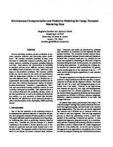
The observations may be of various kinds (e.g., obtained by a class-specific object detector, or motion/color detectors). Here we will consider two different types of observations. 2.2.1 Background subtraction The first type of observations comes from a preprocessing step of background subtraction. Each observation amounts to a connected component of the foreground map after subtracting a reference frame from the current frame (figure 1). The connected components are obtained using the
(a)
(b)
(c)
Figure 1: Observations obtained with background subtraction. (a) Reference frame. (b) Current frame. (c) Result of background subtraction (pixels in black are labeled as foreground) and derived object detections (indicated with red bounding boxes). ”gap/mountain” method described in [34] and ignoring small objects. For the first frame, the tracked objects will be initialized as the observations themselves. 2.2.2 Moving objects detection in complex scenes In order to be able to track objects in more complex sequences, we will use a second type of objects detector. The method considered is the one from [8] that can be decomposed in three main steps.
RR n° 6337
8
Bugeau & P´erez
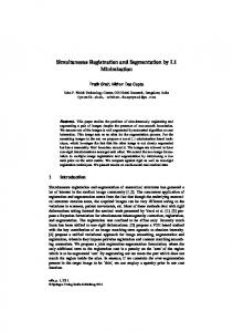
First, a grid of moving pixels having valid flow vectors is selected. Each point is described by its position, its color and its motion. Then these points are partitioned based on a mean shift algorithm [9], leading to several moving clusters, and finally segmentation of the objects are obtained from the moving clusters by performing a graph cuts based segmentation. This last step can be avoided here. Indeed, since in this paper we will propose a method that simultaneously track and segment objects, the observations do not need to be a segmented object. Therefore, the observations will directly be the detected moving clusters (figure 2). The last step of the detection method will only be used when
(a)
(b)
Figure 2: Observations obtained with [8] on a water skier sequence shot by a moving camera. (a) Detected moving clusters superposed on the current frame. (b) Mask of pixels characterizing the observation. initializing new objects to track. When our algorithm outputs that a new tracker should be created from a given observation, the tracker is initialized with the corresponding segmented detected object. In the detection method, flow vectors are only computed on the points of the grid. Therefore, in our tracking algorithm, when using this type of observations, we will keep considering that only the points of the grid are characterized by a motion and a color vector. All the other points will only be characterized by their color. The motion field is then really sparse here.
3 Principle of the method Before presenting our approach into detail, we start by presenting its main principle. In particular, we explain why it is decomposed into two steps (first a segmentation/tracking method and then, when necessary, a further segmentation step) and why each object is tracked independently.
3.1 Tracking each object independently We propose in this paper a tracking method based on energy minimizations. Minimizing an energy with min-cut/max-flow [7] (also known as Graph Cuts) permits to assign a label to each pixel of an image. As in [5], the labeling of one pixel will here depend on the closeness between the appearance at a pixel and the objects appearances and also on the similarity between this pixel and its neighbor. Indeed, a smoothness binary term that encourages two neighboring having close appearance to get the same label is added to the energy function. In our tracking scheme, we wish to assign a label corresponding to one of the tracked objects to each pixel of the image. By using a multi-label energy function (each label corresponding to one object), all objects would be directly tracked simultaneously by minimizing a single energy function. However, in our algorithm, we do not use such an energy and each object will be tracked independently. Such a choice comes from the will to distinguish the merging of several objects from the
INRIA
Track and Cut: simultaneous tracking and segmentation of multiple objects with graph cuts
9
occlusions of some objects by another one, which can not be done using a multi-label energy function. Let us illustrate this problem on an example. Assume that two objects having similar appearance are tracked. We are going to analyze and compare the two following scenarios (described on figure 3). On the one hand, we suppose that the two objects become connected in the image plane at time t
Figure 3: Merge of several objects or occlusion? and, on the other hand, that one of the objects occludes the second one at time t. First, suppose that these two objects are tracked using a multi-label energy function. Since the appearance of the objects is similar, when they get side by side (first case), the minimization will tend to label all the pixels in the same way (due to the smoothness term). Hence, each pixel will probably be assigned the same label, corresponding to only one of the tracked objects. In the second case, when one object occludes the other one, the energy minimization leads to the same result: all the pixels have the same label. Therefore, it is possible for these two scenarios to be mixed up. Assume now that each object is tracked independently by defining one energy function per object (each object is then associated to kt−1 labels). For each object the final label is either ”object” or ”background”. For the first case, each pixel of the two objects will be, at the end of the two minimizations, labeled as ”object”. For the second case, the pixels will be labeled as ”object” when the minimization is done for the occluding object and as ”background” for the occluded one. Therefore, by defining one energy function per object, we are able to differentiate the two cases. Of course, for the first case, the obtained result is not the wanted one: the pixels get the same label which means that the two objects have merged. In order to keep differentiating the two objects, we will add to our tracking method a step of separation of the merged objects. The principles of the tracking and the separation of merged objects are explained in next subsections.
3.2 Principle of the tracking method (i) The principle of our algorithm is as follows. A prediction Ot|t−1 ⊂ P is made for each object i of the mean, over all pixels of the object at time t − 1, of optical flow time t − 1. We denote as d(i) t−1 values: P (M) (s) (i) z s∈Ot−1 t−1 (i) . (4) dt−1 = (i) |Ot−1 | (i) by this average optical flow: The prediction is obtained by translating each pixel belonging to Ot−1
(i)
(i)
(i)
Ot|t−1 = {s + dt−1 , s ∈ Ot−1 } . RR n° 6337
(5)
10
Bugeau & P´erez
(i) Using this prediction, the new observations, as well as the distribution p(i) of Ot−1 , an energy t function is built. The energy is minimized using min-cut/max-flow algorithm [7], which gives the new segmented object at time t, Ot(i) . The minimization also provides the correspondences of the object with all the available observations, which directly leads to the creation of new objects to track. Our tracking algorithm is summed up in figure 4. (i)
Ot−1 Prediction
Distributions computation
(i)
Ot|t−1 Construction of the graph
Observations
Energy minimization (Graph Cuts) (i)
Ot
(i)
Correspondances between Ot−1 and the observations Creation of new objects
Figure 4: Principle of the algorithm
3.3 Principle of the segmentation of merged objects At the end of the tracking step, several objects can have merged, i.e. the results of the segmentations for different objects overlap, that is ∩i=1...kt Ot(i) 6= ∅. In order to keep tracking each object separately, the merged objects must be separated. This will be done by adding a multi-label energy minimization.
4 Energy functions We define one tracker for each object. To each tracker corresponds, for each frame, one graph and one energy function that is minimized using the min-cut/max-flow algorithm [7]. Nodes and edges of the graph can be seen in figure 5. In all this paper, we consider a 8-neighborhood system. However, for clarity, on all the figures representing a graph, only a 4-neighborhood is represented.
4.1 Graph The undirected graph Gt = (Vt , Et ) is defined as a set of nodes Vt and a set of edges Et . The set of nodes is composed of two subsets. The first subset is the set of N pixels of the image grid P . is associated a The second subset corresponds to the observations: to each observation mask M(j) t S (j) node n(j) {nt , j = t . We call these nodes ”observation nodes”. The set of nodes thus reads Vt = P Smt 1 . . . mt }. The set of edges is decomposed as follows: Et = EP j=1 EM(j) . The set EP represents all t
unordered pairs {s, r} of neighboring elements of P , and EM(j) is the set of unordered pairs {s, n(j) t }, t
with s ∈ M(j) t . (i) Segmenting the object Ot(i) amounts to assigning a label ls,t , either background, ”bg”, or object, “fg”, to each pixel node s of the graph. Associating observations to tracked objects amounts to INRIA
Track and Cut: simultaneous tracking and segmentation of multiple objects with graph cuts
11
(i)
Ot|t−1
(1) nt
(2)
nt Object i at time t-1
Graph for object i at time t
Figure 5: Description of the graph. The left figure is the result of the energy minimization at time t − 1. White nodes are labeled as object and black nodes as background. The optical flow vectors for the object are shown in blue. The right figure shows the graph at time t. Two observations are available, each of which giving rise to a special “observation” node. The pixel nodes circled in red correspond to the masks of these two observations. Dashed box indicates predicted mask.
(j)
(i) assigning a binary label lj,t (“bg” or “fg”) to each observation node nt . The set of all the node (i) labels forms Lt .
4.2 Energy An energy function is defined for each object i at each instant t. It is composed of unary data terms (i) (i) Rs,t and smoothness binary terms Bs,r,t : X X (i) (i) (i) (i) (i) (i) (i) (6) Rs,t (ls,t ) + Et (Lt ) = B{s,r},t (1 − δ(ls,t , lr,t )). s∈Vt
{s,r}∈Et
In order to simplify the notations, we omit in the rest of this section the index i. Previous equation is then rewritten as: X X Et (Lt ) = B{s,r},t (1 − δ(ls,t , lr,t )). (7) Rs,t (ls,t ) + s∈Vt
{s,r}∈Et
4.2.1 Data term The data term only concerns the pixel nodes lying in the predicted regions and the observation nodes. For all the other pixel nodes, labeling will only be controlled by the neighbors via binary terms. More precisely, the first part of energy in (7) reads: X
s∈Vt
Rs,t (ls,t ) =
X
s∈Ot|t−1
−ln(p1 (s, ls,t )) + α
mt X
d2 (j, lj,t ).
(8)
j=1
Segmented object at time t should be similar, in terms of motion and color, to the preceding instance of this object at time t − 1. To exploit this consistency assumption, the distribution of the (i) object, p(i) t−1 (equation 1), and of the background, qt−1 (equation 2), from previous image, are used. Remember that we chose to omit the index of the object. Previous distributions are then denoted as pt−1 and qt−1 . The likelihood p1 , within predicted region, is finally defined as: � pt−1 (zt (s)) if l = “fg”, p1 (s, l) = (9) qt−1 (zt (s)) if l = “bg” . In the same way, an observation should be used only if it is likely to correspond to the tracked object. To evaluate the similarity of observation j at time t and object i at previous time, a comparison RR n° 6337
12
Bugeau & P´erez
(j) (i) between the distributions p(i) (equation 3) and between qt−1 and ρ(j) must be performed t t−1 and ρt through the computation of a distance measure. A classical distance to compare two mixtures of Gaussians, G1 and G2 , is the Kullback-leibler distance [22], defined as: Z G1 (x) dx. (10) KL(G1 , G2 ) = G1 (x)log G2 (x)
The likelihood p1 , is finally: d2 (s, l) =
(
(j)
KL(ρt , pt−1 ) if l = “fg”,
(11)
(j)
KL(ρt , qt−1 ) if l = “bg” .
A constant α is included in the data term in equation (8) to give more or less influence to the observations. As only one node is used to represent the whole mask of pixels of an observation, we have chosen to fix α equal to the number of pixels belonging to the observation, that is α = |M(j) t |. 4.2.2 Binary term Following [5], the binary term between neighboring pairs of pixels {s, r} of P is based on color gradients and has the form B{s,r},t = λ1
− 1 e dist(s, r)
(C) (C) kzt (s)−zt (r)k2 σ2 T
.
(12)
(C) (s) − zt (r))2 i, where h.i denotes expectation As in [4], the parameter σT is set to σT = 4 · h(z(C) t over a box surrounding the object. For edges between one pixel node and one observation node, the binary term depends on the distance between the color of the observation and the pixel color. More precisely, it is computed as
(j)
(C)
B{s,n(j) },t = λ2 ρt (zt t
(s)).
(13)
Parameters λ1 and λ2 are discussed in the experiments. 4.2.3 Energy minimization The final labeling of pixels is obtained by minimizing, with ‘the “Expansion Move” algorithm [7], the energy defined above: (i) (i) ˆ (i) L (14) t = arg min Et (Lt ). (i)
Lt
This labeling gives the segmentation of the i-th object at time t as: (i) (i) Ot = {s ∈ P : ˆls,t = “fg”}.
(15)
4.3 Creation of new objects One advantage of our approach lies in its ability to jointly manipulate pixel labels and track-todetection assignment labels. This allows the system to track and segment the objects at time t while establishing the correspondence between an object currently tracked and all the approximative object candidates obtained by detection in current frame. If, after the energy minimization for an object i, an (i) is labeled as “fg” (ˆlt,j = “fg”) it means that there is a correspondence between observation node n(j) t
INRIA
Track and Cut: simultaneous tracking and segmentation of multiple objects with graph cuts
13
the i-th object and the j-th observation. Conversely, if the node is labeled as “bg”, the object and the observation are not associated. (i) If for all the objects (i = 1, . . . , kt−1 ), an observation node is labeled as “bg” (∀i, ˆlt,j = “bg”), then the corresponding observation does not match any object. In this case, a new object is created and initialized with this observation. The number of tracked objects becomes kt = kt−1 + 1, and the new object is initialized as: (k ) (j) Ot t = Mt . In practice, the creation of a new object will only be validated if the new object is associated to at (i) least one observation at time t + 1, i.e., if ∃ j ∈ {1 . . . mt+1 } such that ˆlj,t+1 = “fg”.
5 Segmenting merged objects Assume now that the results of the segmentations for different objects overlap, that is (i)
∩i∈F Ot 6= ∅, where F denotes the current set of object indices. In this case, we propose an additional step to determine whether these objects truly correspond to the same one or if they should be separated. At the end of this step, each pixel of ∩i∈F Ot(i) must belong to only one object. For this purpose, a new ˜ t = (V˜t , E˜t ) is created, where V ˜t = ∪i∈F Ot(i) and E˜t is composed of all unordered pairs of graph G neighboring pixel nodes of V˜t . An exemple of such a graph is presented on figure 6.
Figure 6: Graph example for the segmentation of merged objects. The goal is then to assign to each node s of V˜t a label ψs ∈ F . Defining L˜ = {ψs , s ∈ V˜t } the labeling of V˜t , a new energy is defined as: (C)
˜ = E˜t (L)
X
˜t s∈V
−ln(p3 (s, ψs )) + λ3
X
{s,r}∈E˜t
kz − s 1 e dist(s, r)
(C) 2 −zr k 2 σ3
(1 − δ(ψs , ψr )).
(16)
The parameter σ3 is here set as σ3 = 4 · h(zt (s)(i,C) − zt (r)(i,C) )2 i with the averaging being over i ∈ F and {s, r} ∈ E˜. The fact that several objects have been merged shows that their respective feature distributions at previous instant did not permit to distinguish them. A way to separate them is then to increase the role of the prediction. This is achieved by choosing function p3 as: ( (ψ) (ψ) pt−1 (zt (s)) if s ∈ / Ot|t−1 , p3 (s, ψ) = (17) 1 otherwise . RR n° 6337
14
Bugeau & P´erez
This multi-label energy function is minimized using the swap algorithms [6, 7]. After this minimization, the objects Ot(i) , i ∈ F are updated.
6 Experimental Results This section presents various results of the tracking and the separation of merged objects. First, we will consider a relatively simple sequence, with static background, in which the observations are obtained by background subtraction (subsection 2.2.1). Next the tracking method will be combined to the moving objects detector of [8] (subsection 2.2.2). For all results, a color is associated to each tracked object. This color only depends on the arbitrary order in which the objects are created.
6.1 Tracking objects detected with background subtraction We start by demonstrating, on a sequence from the PETS 2006 data corpus (sequence 1 camera 4), the validity of the tracking method as well as the robustness to partial occlusions and the individual segmentation of objects that were initially merged. Following [4], the parameter λ3 was set to 20. However parameters λ1 and λ2 had to be tuned by hand to get better results. Indeed, λ1 was set to 10 while λ2 to 2. Also, the number of classes for the Gaussian mixture models was set to 10. First results (figure 7) demonstrate the good behavior of our algorithm even in the presence of partial occlusions and of object fusion. Observations, obtained by subtracting reference frame (frame 10 shown on figure 1(a)) to the current one, are visible in the second column of figure 7. The third column contains the segmentation of the objects with the use of the second energy function. In frame 81, two objects are initialized using the observations. Note that the connected component extracted with the “gap/mountain” method misses the legs for the person in the upper right corner. While this impacts the initial segmentation, the legs are included in the segmentation as soon as the subsequent frame. The proposed methods deals easily with the entrance of new objects in the scene. This result also shows the robustness of our method to partial occlusions. Partial occlusions occur when the person at the top passes behind the three other ones (frames 176 and 206). Despite the similar color of all the objects, this is well handled by the method, as the person is still tracked when the occlusion stops (frame 248). Finally note that, even if from the 102nd frame the two persons at the bottom of the frames correspond to only one observation and have a similar appearance (color and motion), our algorithm tracks each person separately (frames 116, 146). In figure 8, we show in more details the influence of the second energy function by comparing the results obtained with and without it. Before frame 102, the three persons at the bottom generate three distinct observations while, passed this instant, they correspond to only one or two observations. Even if the motions and colors of the three persons are very close, the use of the secondary multi-label energy function allows their separation.
6.2 Tracking objects in complex scenes We are now going to show the behaviour of our tracking algorithm when the sequences are more complex (dynamic background, moving camera ...). For each sequence, the observations are the moving clusters detected with the method of [8]. In all this subsection, the parameter λ3 was set to 20, λ1 to 10, and λ2 to 1. The first result is on a water skier sequence (figure 9). For each image, the moving clusters and the
INRIA
Track and Cut: simultaneous tracking and segmentation of multiple objects with graph cuts
(a)
(b)
15
(c)
Figure 7: Results on sequence from PETS 2006 (frames 81, 116, 146, 176, 206 and 248). (a) Original frames. (b) Result of simple background subtraction and extracted observations. (c) Tracked objects on current frame using the secondary energy function.
RR n° 6337
16
Bugeau & P´erez
(a)
(b)
(c)
Figure 8: Separating merged objects with the secondary minimization (frames 101 and 102). (a) Result of simple background subtraction and extracted observations. (b) Segmentations with primary energy functions only. (c) Segmentation after post-processing with the secondary energy function. masks of the tracked objects are superimposed on the original image. The proposed tracking method permits to track correctly the water skier (or more precisely his wet suit) all along the sequence, despite the trajectory changes. As can be seen on the figure (for example at time 58), the detector sometimes fails to detect the skier. No observations are then available. However, thanks to the use of the prediction of the object, our method handles well this kind of situations and keeps tracking and segmenting correctly the skier. This shows the robustness of the algorithm to missing observations. However if some observations are missing for several consecutive frames, the segmentation can be a bit deteriorated. Conversely, this means that the incorporation of observations from the detection module enables to get better segmentations than when using only predictions. On several frames, some moving clusters are detected in the water. Nevertheless, no objects are created in this area. The reason is that the creation of a new object is only validated if the new object is associated to at least one observation in the following frame. This never happened in the sequence. We end by showing results on a driver sequence (figure 10). The first object detected and tracked is the face. Once again, tracking this object shows the robustness of our method to missing observations. Indeed, even if from frame 19, the face does not move and therefore is not detected, the algorithm keeps tracking and segmenting it correctly until the driver starts turning it. The most important result on this sequence is the hands tracking. In image 39, the masks of the two hands are merged: they have a few pixels in common. The step of segmentation of merged objects is then applied which allows the correct separation of the two masks and permits to keep tracking these two objects separately. Finally, as can been seen on frame 57, our method deals well with the exit of an object from the scene.
7 Conclusion In this paper we have presented a new method to simultaneously segment and track objects. Predictions and observations, composed of detected objects, are introduced in an energy function which is minimized using graph cuts. The use of graph cuts permits the segmentation of the objects at a modest computational cost (of course the computational time depends on the objects detection and the distributions computation). A novelty is the use of observation nodes in the graph which gives better segmentations but also enables the direct association of the tracked objects to the observations (without adding any association procedure). The algorithm is robust to partial occlusions, progressive illumination changes and to missing observations. Thanks to the use of a secondary multi-label
INRIA
Track and Cut: simultaneous tracking and segmentation of multiple objects with graph cuts
t = 31
t = 177
t = 51
t = 215
t = 58
t = 225
t = 80
t = 243
17
Figure 9: Results on a water skier sequence. The observations are moving clusters detected with the method in [8]. At each time, the observations are shown on the left image while the masks of the tracked objects are shown on the right image. energy function, our method allows individual tracking and segmentation of objects which where not distinguished from each other in the first stage. The observations used in this paper are obtained firstly by a simple background subtraction based on a single reference frame and secondly by a more complicated moving object detector. Note however that any object detection method could be used as well with no change to the approach, as soon as the observations can be represented by a mask of pixels. As we use feature distributions of objects at previous time to define current energy functions, our method breaks down in extreme cases of abrupt illumination changes. However, by adding an external detector of such changes, we could circumvent this problem by keeping only the prediction and by updating the reference frame when the abrupt change occurs. Also, other cues, such as shapes, could probably be added to improve the results. Apart from this rather specific problem, several research directions are open. One of them concerns the design of an unifying energy framework that would allow segmentation and tracking of
RR n° 6337
18
Bugeau & P´erez
t = 13
t = 39
t = 16
t = 43
t = 29
t = 57
t = 35
t = 63
Figure 10: Results on a driver sequence. The observations are moving clusters detected with the method in [8]. At each time, the observations are shown on the left image while the masks of the tracked objects are shown on the right image. multiple objects while precluding the incorrect merging of similar objects getting close to each other in the image plane. Another direction of research concerns the automatic tuning of the parameters, which remains an open problem in the recent literature on image labeling (e.g., figure/ground segmentation) with graph-cuts.
References [1] Y. Bar-Shalom and X. Li. Estimation and Tracking: Principles, Techniques, and Software. MA: Artech House, Boston, 1993.
INRIA
Track and Cut: simultaneous tracking and segmentation of multiple objects with graph cuts
19
[2] Y. Bar-Shalom and X. Li. Multisensor-multitarget tracking: Principles and Techniques. CT: YBS Publishing, Storrs, 1995. [3] M. Bertalmio, G. Sapiro, and G. Randall. Morphing active contours. IEEE Trans. Pattern Anal. Machine Intell., 22(7):733–737, 2000. [4] A. Blake, C. Rother, M. Brown, P. P´erez, and P. Torr. Interactive image segmentation using an adaptive gmmrf model. In Proc. Europ. Conf. Computer Vision, 2004. [5] Y. Boykov and M. Jolly. Interactive graph cuts for optimal boundary and region segmentation of objects in n-d images. Proc. Int. Conf. Computer Vision, 2001. [6] Y. Boykov, O. Veksler, and R. Zabih. Markov random fields with efficient approximations. In Proc. Conf. Comp. Vision Pattern Rec., 1998. [7] Y. Boykov, O. Veksler, and R. Zabih. Fast approximate energy minimization via graph cuts. IEEE Trans. Pattern Anal. Machine Intell., 23(11):1222–1239, 2001. [8] A. Bugeau and P. P´erez. Detection and segmentation of moving objects in highly dynamic scenes. Proc. Conf. Comp. Vision Pattern Rec., 2007. [9] D. Comaniciu and P. Meer. Mean shift: A robust approach toward feature space analysis. IEEE Trans. Pattern Anal. Machine Intell., 24(5):603–619, 2002. [10] D. Comaniciu, V. Ramesh, and P. Meer. Real-time tracking of non-rigid objects using meanshift. In Proc. Conf. Comp. Vision Pattern Rec., 2000. [11] D. Comaniciu, V. Ramesh, and P. Meer. Kernel-based optical tracking. IEEE Trans. Pattern Anal. Machine Intell., 25(5):564–577, May 2003. [12] I. Cox. A review of statistical data association for motion correspondence. Int. J. Computer Vision, 10(1):53–66, 1993. [13] D. Cremers and C. C. Schn¨orr. Statistical shape knowledge in variational motion segmentation. Image and Vision Computing, 21(1):77–86, 2003. [14] A. Criminisi, G. Cross, A. Blake, and V. Kolmogorov. Bilayer segmentation of live video. Proc. Conf. Comp. Vision Pattern Rec., 2006. [15] D. Freedman and M. Turek. Illumination-invariant tracking via graph cuts. Proc. Conf. Comp. Vision Pattern Rec., 2005. [16] N. Gordon, D. Salmond, and A. Smith. Novel approach to nonlinear/non-gaussian bayesian state estimation. IEEE Proceedings on Radar and Signal Processing, 1993. [17] M. Isard and A. Blake. Condensation – conditional density propagation for visual tracking. Int. J. Computer Vision, 29(1):5–28, 1998. [18] O. Juan and Y. Boykov. Active graph cuts. In Proc. Conf. Comp. Vision Pattern Rec., 2006. [19] R. Kalman. A new approach to linear filtering and prediction problems. J. Basic Eng., 82:35–45, 1960. [20] R. Kjeldsen and J. Kender. Finding skin in color images. International Conference on Automatic Face and Gesture Recognition, 1996.
RR n° 6337
20
Bugeau & P´erez
[21] P. Kohli and P. Torr. Effciently solving dynamic markov random fields using graph cuts. In Proc. Int. Conf. Computer Vision, 2005. [22] S. Kullback and R. A. Leibler. On information and sufficiency. Annals of Mathematical Statistics, 22(1):79–86, March 1951. [23] B.D. Lucas and T. Kanade. An iterative technique of image registration and its application to stereo. Proc. Int. Joint Conf. on Artificial Intelligence, 1981. [24] J. MacCormick and A. Blake. A probabilistic exclusion principle for tracking multiple objects. Int. J. Computer Vision, 39(1):57–71, 2000. [25] A. Mansouri. Region tracking via level set pdes without motion computation. IEEE Trans. Pattern Anal. Machine Intell., 24(7):947–961, 2002. [26] N. Paragios and R. Deriche. Geodesic active regions for motion estimation and tracking. In Proc. Int. Conf. Computer Vision, 1999. [27] N. Paragios and G. Tziritas. Adaptive detection and localization of moving objects in image sequences. Signal Processing: Image Communication, 14:277–296, 1999. [28] D Reid. An algorithm for tracking multiple targets. IEEE Trans. Autom. Control, 24(6):843– 854, 1979. [29] R. Ronfard. Region-based strategies for active contour models. Int. J. Computer Vision, 13(2):229–251, 1994. [30] J. Shi and C. Tomasi. Good features to track. Proc. Conf. Comp. Vision Pattern Rec., 1994. [31] Y. Shi and W. Karl. Real-time tracking using level sets. Proc. Conf. Comp. Vision Pattern Rec., 2005. [32] M. Singh and N. Ahuja. Regression based bandwidth selection for segmentation using parzen windows. Proc. Int. Conf. Computer Vision, 1, 2003. [33] D. Terzopoulos and R. Szeliski. Tracking with kalman snakes. Active vision, pages 3–20, 1993. [34] Y. Wang, J.F. Doherty, and R.E. Van Dyck. Moving object tracking in video. Applied Imagery Pattern Recognition (AIPR) Annual Workshop, 2000. [35] N. Xu and N. Ahuja. Object contour tracking using graph cuts based active contours. Proc. Int. Conf. Image Processing, 2002. [36] A. Yilmaz. Contour-based object tracking with occlusion handling in video acquired using mobile cameras. IEEE Trans. Pattern Anal. Machine Intell., 26(11):1531–1536, 2004. [37] A. Yilmaz, O. Javed, and M. Shah. Object tracking: A survey. ACM Comput. Surv., 38(4):13, 2006.
INRIA
Unité de recherche INRIA Rennes IRISA, Campus universitaire de Beaulieu - 35042 Rennes Cedex (France) Unité de recherche INRIA Futurs : Parc Club Orsay Université - ZAC des Vignes 4, rue Jacques Monod - 91893 ORSAY Cedex (France) Unité de recherche INRIA Lorraine : LORIA, Technopôle de Nancy-Brabois - Campus scientifique 615, rue du Jardin Botanique - BP 101 - 54602 Villers-lès-Nancy Cedex (France) Unité de recherche INRIA Rhône-Alpes : 655, avenue de l’Europe - 38334 Montbonnot Saint-Ismier (France) Unité de recherche INRIA Rocquencourt : Domaine de Voluceau - Rocquencourt - BP 105 - 78153 Le Chesnay Cedex (France) Unité de recherche INRIA Sophia Antipolis : 2004, route des Lucioles - BP 93 - 06902 Sophia Antipolis Cedex (France)
Éditeur INRIA - Domaine de Voluceau - Rocquencourt, BP 105 - 78153 Le Chesnay Cedex (France)
http://www.inria.fr ISSN 0249-6399