structure MIH within the frame work of the macroscopic dielectric continuum model. Furthermore, the optical-phonon normalization condition is generalized to ...
Transfer matrix method for interface optical-phonon modes in multiple-interface heterostructure systems SeGi Yua) and K. W. Kim Department of Electrical and Computer Engineering, North Carolina State University, Raleigh, North Carolina 27695-7911
Michael A. Stroscio and G. J. Iafrate U. S. Army Research Office, P. O. Box 12211, Research Triangle Park, North Carolina 27709-2211
J.-P. Sun and G. I. Haddad Department of Electrical Engineering and Computer Science, University of Michigan, Ann Arbor, Michigan 48109-2122
~Received 6 January 1997; accepted for publication 24 June 1997! Interactions of carriers with interface optical phonons dominate over other carrier–phonon scatterings in narrow quantum-well structures. Herein, a transfer matrix method is used to establish a formalism for determining the dispersion relations, electrostatic potentials, and Fro¨hlich interaction Hamiltonians of the interface optical phonons for multiple-interface heterostructure systems within the framework of the macroscopic dielectric continuum model. This method facilitates systematic calculations for complex structures where the conventional method is very difficult to implement. Several specific cases are treated to illustrate the advantages of the general formalism. © 1997 American Institute of Physics. @S0021-8979~97!03019-3#
I. INTRODUCTION
It is well known that confinement effects modify both acoustic and optical-phonon modes as well as their interactions with carriers in semiconductor nanostructures.1 For narrow polar–semiconductor quantum wells, carrier interactions with interface optical ~IF! phonons play a dominate role in carrier energy relaxation processes.2 Such narrow quantumwell systems have been of extreme importance in recent studies of unipolar semiconductor lasers, which now produce infrared radiation in room-temperature operation.3 In theoretical treatments of electron-optical-phonon interactions in heterostructures, both macroscopic4–9 and microscopic10 approaches have been applied. Detailed microscopic calculations of optical-phonon modes in polar semiconductors indicate that the dielectric continuum model provides an accurate formalism for modeling electron-optical-phonon interactions.10 However, most of these theoretical analyses have been confined to highly symmetric and/or simple structures such as single or double quantum wells composed of binary semiconductors. Application of even a simple macroscopic model, not to mention the microscopic ab initio models, becomes highly complicated due to the coupling between adjacent interfaces when the structure has multiple heterointerfaces or is asymmetric. At the same time, ternary or quaternary materials may be used along with the binary material systems. In this work, we develop a general transfer matrix formalism to determine the electrostatic potentials and dispersion relations of IF phonons in a multiple-interface heterostructure ~MIH! within the frame work of the macroscopic dielectric continuum model. Furthermore, the optical-phonon normalization condition is generalized to derive the Fro¨hlich a!
Also with the Department of Physics, North Carolina State University, Raleigh, NC 27695-8202.
J. Appl. Phys. 82 (7), 1 October 1997
interaction Hamiltonian for IF phonons in this multilayered system composed of polar semiconductors. As in the calculation of electronic envelope functions,11 the transfer matrix treatment for the IF phonons reduces the complex derivation of the potential to a simple matrix multiplication. A number of examples are provided to illustrate the advantages of the general formalism. II. TRANSFER MATRIX METHOD
The electrostatic potentials and the corresponding dispersion relations for IF phonons in an arbitrary heterostructure may be obtained by applying the transfer matrix technique in a manner similar to the electronic envelope functions. As is well known, the electrostatic potentials of IF phonon modes4–9 are linear combinations of exponentially growing and exponentially damped spatial functions. Specifically, for a given IF phonon mode in an n-interface heterostructure, as depicted in Fig. 1~a!, the electrostatic potential F i (r) in the region Ri 5 @ z i ,z i11 # and its twodimensional Fourier transform F i (q,z) are defined by F i ~ r! 5
(q e 2iq• rF i~ q,z ! ,
F i ~ q,z ! 5c i2 e 2qz 1c i1 e 1qz [c i2 f i2 1c i1 f i1 ,
~1! ~2!
where r5(x,y) and q denote the position and wave vector in the two-dimensional plane of the interface. The z axis is chosen as the direction of crystal growth. Furthermore, electrostatic boundary conditions of the dielectric continuum model for IF phonons require that the electrostatic potential and the tangential component of the electric field be continuous;4–7 thus, F i (z) and e i ( ] / ] z)F i (z) must be continuous at each interface. It then follows that at z5z i , i.e., at the interface between the regions Ri and Ri21 , F i ~ q,z i ! 5F i21 ~ q,z i ! ,
0021-8979/97/82(7)/3363/5/$10.00
© 1997 American Institute of Physics
~3! 3363
e i~ v ! 5 e i~ ` !
2 v 2 2 v LO 2 v22vTO
~10!
,
for a binary compound semiconductor or as a double-pole function,
e i~ v ! 5 e i~ ` !
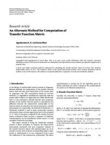
FIG. 1. Schematic drawing of ~a! an arbitrary n-interface heterostructure; and conduction-band-edge profiles for ~b! single-barrier, ~c! multiplebarrier, and ~d! five-interface asymmetric heterostructures used in the calculations. In ~c!, the distance between each barrier is assumed to be 2a. The z axis is chosen as the growth direction of the structures.
] ] F ~ q,z i ! 5 e i21 F ~ q,z i ! . ei ]z i ] z i21
~4!
These results can be written compactly in a matrix form as follows: Mi ~ z i ! Ci 5Mi21 ~ z i ! Ci21 .
~5!
Here, the definitions of the matrices Ci and Mi (z) are given by Ci 5
S D
c i2 , c i1
Mi ~ z ! 5
S
~6!
f i2 ~ z !
f i1 ~ z !
8 ~z! e i f i2
8 ~z! e i f i1
D
.
~7!
By applying the chain rule, the matrix Ci may be expressed as Ci 5Qi ~ z i ! Ci21 5Qi ~ z i ! Qi21 ~ z i21 ! •••Q1 ~ z 1 ! C0 ,
~8!
where a transfer matrix Qi (z i ) is defined as Mi (z i ) 21 Mi21 (z i ) relating the regions Ri21 and Ri . Thus, given the matrix C0 for the region R0 and the matrix Qi , the electrostatic potential F i (q,z) can be determined in any region of the structure by following the sequence of Eq. ~8!. Finally, the phonon potential for the n-interface heterostructure is the combination of F i for each region Ri , i.e.,
F ~ q,z ! 5
5
F 0 ~ q,z ! ,
zPR0
A F i ~ q,z ! ,
zPRi
~9!
A F n ~ q,z ! ,
zPRn .
Following the generalized Lyddane–Sachs–Teller relation, the dielectric function e i for the region Ri in Eqs. ~4! and ~7! may be taken as that of a single-pole function, 3364
J. Appl. Phys., Vol. 82, No. 7, 1 October 1997
2 2 !~ v 2 2 v LOB ! ~ v 2 2 v LOA 2 2 !~ v 2 2 v TOB ! ~ v 2 2 v TOA
,
~11!
which provides an approximate dielectric function for a ternary compound semiconductor.12 Moreover, extension to more complex systems such as quaternary semiconductors may be possible by using an appropriate form of the dielectric function. In Eqs. ~10! and ~11!, LO ~TO! stands for the longitudinal ~transverse! optical mode, and A and B denote material types. The dispersion relation for a particular IF phonon mode is obtained by requiring c n1 50 and c 02 50. This choice leads to admissible ~exponentially decreasing! solutions as z approaches 6`. Thus, with Eq. ~8!, it follows that the dispersion relation of the mode under consideration is determined by setting the ~2,2! component of the transfer matrix to zero, i.e., @ Qn ~ z n ,q, v ! Qn21 ~ z n21 ,q, v ! •••Q1 ~ z 1 ,q, v !# i j 50,
i5 j52.
~12!
Once the wave-vector dependence of v is obtained, the problem of determining the potential reduces to matrix multiplication, as indicated by Eq. ~8!. Indeed, these matrix equations define the coefficients in our general expression for the phonon potential of Eq. ~9!. This procedure can be completed for each of the IF phonon mode solutions for MIHs. The number of IF phonon modes in an n-interface heterostructure is readily determined by examination of the dispersion relation of Eq. ~12!. Specifically, Qi is proportional to e i ( v ) e i21 ( v ). Thus, with n interfaces, Cn is a product of n Q matrices and C0 . For a MIH composed of the binary layers only, the v 2 dependence in the dispersion relation goes as a function of ( v 2 ) 2n due to the adoption of the onepole model of dielectric function @Eq. ~10!#. Hence, for an n-interface all-binary heterostructure, there are 2n IF phonon modes. For a MIH with alternating binary and ternary layers, there are 3n modes, since there are two binarylike modes for the ternary layer. The number of physical IF modes for a MIH of general composition is readily determined from the product of all of the appropriate e i ( v ) entering into Eq. ~8!.
III. NORMALIZATION OF IF PHONON MODES
The transfer matrix solutions of Sec. II provide all the information needed to completely specify the functional forms of the IF phonon modes in MIH systems. However, the overall normalization constant for each mode must be derived in a manner that is compatible with the transfer matrix method. For the i-th region of the MIH structure, the IF phonon potential is given by Eqs. ~1! and ~2!. From this potential, it follows that the electric-field E and polarization P associated with the IF phonon potential in the region Ri are given by Yu et al.
Ei ~ q,z ! 52“F i ~ q,z ! 52iqF i ~ q,z ! qˆ 2
] F i ~ q,z ! zˆ , ]z ~13!
S
D
and
Pi ~ q,z ! 52 e 0 x i ~ v ! iqF i ~ q,z ! qˆ 1
] F i ~ q,z ! zˆ , ]z
~14!
where qˆ and zˆ are the unit vectors for q and the z direction, respectively. Assuming the standard forms5–7,12 for the continuum expressions of the ionic force equation and the polarization of the polar medium,
mi
d2 loc u ~ r,t ! 52 m i v 20i ui ~ r,t ! 1e * i Ei ~ r,t ! , dt 2 i
~15!
and Pi ~ r,t ! 5n i e i* ui ~ r,t ! 1n i a i Eloc i ~ r,t ! ,
~16!
where u~r! is the relative displacement of an ion pair ~i.e., a unit cell!, m i is the reduced mass of an ion pair, v 0i is the frequency associated with the short-range forces between ions, e * i is the effective charge of a unit cell, n i is the number of unit cells per unit volume, and a i is the electronic polarizability per unit cell. The local electric-field Eloc is given by the Lorentz relation as Eloc 5E1P/3e 0 . From an appropriate generalization of the optical-phonon normalization condition,4,5,12
(i L 2 ER dz u Am i n i ui~ q,z ! u 2 5 2 v , \
~17!
i
and the relation between the displacement and potential,12 i.e.,
S
u Am i n i ui ~ q,z ! u 2 5 q 2 u F i ~ q,z ! u 2
1
U
] F i ~ q,z ! ]z
UD 2
e0
1 ] e i~ v ! . 2 v ]v
~18!
From Eqs. ~17! and ~18!, it follows that the normalization of the potential of each IF phonon mode is given by \ 5 2v
(i 1
U
E S
e 0 ] e i~ v ! 2 v ]v ] F i ~ q,z ! ]z
UD
Ri
dz q 2 u F i ~ q,z ! u 2
2
.
~19!
The result of Eq. ~19! is derived for both binary and ternary systems and may be applicable to more complex materials as well, if an appropriate expression is used for the dielectric function following the scheme of Ref. 12. Finally, the Fro¨hlich interaction Hamiltonian is given directly in terms of the potential; i.e., H F 5e
† 1a q! , (q e 2iq• rF ~ q,z !~ a 2q
~20!
where the functional form and the normalization of F(q,z) are given by Eqs. ~1! and ~19!, respectively, as discussed before. J. Appl. Phys., Vol. 82, No. 7, 1 October 1997
FIG. 2. ~a! Dispersion relations and ~b! electrostatic potentials of the IF phonons for the two-interface ~single-barrier! GaAs–Alx Ga12x As–GaAs heterostructure of Fig. 1~b! with an Al mole fraction x of 0.6. S(A) denotes the symmetric ~antisymmetric! modes; 1, 2, and 3 correspond to the lower GaAs, upper GaAs, and AlAs modes, respectively. The arrows on the right vertical axis of ~a! represent the phonon frequencies of GaAs-like TO~Al0.6Ga0.4As), GaAs-like LO~Al0.6Ga0.4As), TO~GaAs!, LO~GaAs!, AlAs-like TO~Al0.6Ga0.4As), and AlAs-like LO~Al0.6Ga0.4As) in the ascending order in frequencies. The unit for the wave vector is qa, and that for the position is a. In ~b!, the wave vector is taken to be qa50.5.
IV. APPLICATION OF TRANSFER MATRIX FORMALISM
As an example of the application of the general transfer matrix method, we consider the two-interface heterostructure of Fig. 1~b! and examine the influence of the ternary material. The IF phonon modes for this single-barrier structure are complicated by the fact that the Alx Ga12x As ternary barrier layer has both AlAs-like and GaAs-like modes. By applying the transfer matrix method, the dispersion relations and phonon potentials for the six allowed IF modes are found to be those presented in Fig. 2 ~with an Al mole fraction x of 0.6!. The values for the dielectric constants and the phonon frequencies of GaAs, AlAs, and Alx Ga12x As used in these calculations are shown in Table I.13 The high-frequency symmetric and antisymmetric modes ~v 3S and v 3A ! show similar behavior for the corresponding AlAs–GaAs heterostructure, these IF phonon frequencies fall near the zone-center LO and TO phonon frequencies of AlAs modes similar to the results of Ref. 5. However, there are four GaAs-like modes; this is Yu et al.
3365
TABLE I. Dielectric constants and phonon frequencies used in the dispersion relation calculation.
e` \ v LO \ v TO \ v LO \ v TO
~GaAs-like! ~meV! ~GaAs-like! ~meV! ~AlAs-like! ~meV! ~AlAs-like! ~meV!
GaAs
AlAs
Alx Ga12x As
10.89 36.25 33.29 ••• •••
8.16 ••• ••• 50.09 44.88
10.89 2 2.73 3 x 36.2526.553x11.793x 2 33.2920.643x21.163x 2 44.6318.783x23.323x 2 44.6310.553x20.303x 2
double the number found for the corresponding AlAs–GaAs structure. The upper two mode frequencies ~v 2S and v 2A ! fall between the LO and TO phonon frequencies of GaAs, while the lower two mode frequencies ~v 1S and v 1A ! fall between the LO and TO phonon frequencies of Alx Ga12x As as indicated by the arrows in Fig. 2~a!. This result is expected since the GaAs-like mode frequency in the Alx Ga12x As ternary barrier region differs from the GaAs mode frequency in the regions adjacent to the barrier. Hence, a doubling of the GaAs phonon modes arises from the formation of IF modes that are joint modes of the slightly different GaAs-like modes of the GaAs and Alx Ga12x As materials. Due to the fact that the frequency difference between GaAs-like LO and TO phonons of Alx Ga12x As is very small, the lower GaAs-like IF phonons show little dispersion. In Fig. 2~b!, it is found that within each group of modes ~i.e., AlAs, upper GaAs, and lower GaAs!, the symmetries are approximately the same although the normalizations differ. This is due to the symmetric dielectric function outside the barrier. The structure depicted in Fig. 1~c! represents multiplebarrier heterostructures consisting of binary semiconductors ~e.g., Gas–AlAs!. The transfer matrix method readily yields the dispersion relations of Fig. 3. The results of Fig. 3 are especially interesting, since they illustrate the beginning phases of the formation of phonon minibands in a GaAs– AlAs superlattice, just as minibands are formed for the electronic states in a multiple quantum-well system as the number of wells becomes so large that the structure behaves as a superlattice. As each additional barrier is added to the multiple-barrier system, the number of IF phonon modes increases and the dispersion curves fall in bands around the modes that are present in the single-barrier structure. This
FIG. 3. Dispersion relations of the IF phonons for ~a! one-, ~b! two-, ~c! three-, and ~d! four-barrier AlAs–GaAs heterostructures as well as ~e! those for a superlattice shown in Fig. 1~c!. The GaAs–AlAs material system is assumed. The unit for the wave vector is qa. 3366
J. Appl. Phys., Vol. 82, No. 7, 1 October 1997
FIG. 4. ~a! Dispersion relations of the IF phonons for the five-interface Aly Ga12y As–GaAs–Alx Ga12x As–GaAs–Alx Ga12x As–GaAs heterostructure of Fig. 1~d! with y50.25 and x50.6. 15 modes are grouped into the lower GaAs-like, upper GaAs-like, and AlAs-like modes in the ascending order in frequencies. There are five phonon modes in each group. The lowest two modes of the lower GaAs-like branch are too close to distinguish one from the other. The unit for the wave vector is qa. ~b! Electrostatic potentials vs the distance for the AlAs modes. The line types used to denote the different IF phonon modes correspond to those of ~a!. The value of wave-vector qa is fixed at 0.5 and the unit for the position is a.
means that an m-barrier structure splits each mode of dispersion curves for the single-barrier structure into the m modes. Thus, the formation of phonon minibands is very similar to the formation of electron minibands.14 As shown in Figs. 3~a!–3~e!, the phonon miniband width approaches saturation in only a few periods except in the region where q'0. The central reason for this fast convergence of the phonon miniband width is that the penetration depth of the phonon amplitude is, typically, only one or two monolayers. However, many more periods need to be considered for IF phonons near the zone center due to their long wavelength. For the case of a superlattice, the calculation of phonon dispersion can be much simplified by utilizing the symmetry ~or periodicity! of the structure as discussed in Refs. 15 and 16 although it is possible to apply the transfer matrix method to heterostructures with any number of interfaces. Yu et al.
The structure of Fig. 1~d!, which has been used in recent unipolar laser experiments,17,18 contains GaAs wells and barrier regions of both Aly Ga12y As and Alx Ga12x As with y 50.25 and x50.6. The dispersion relations determined by the transfer matrix approach for this structure are given in Fig. 4~a!. Among 15 IF modes, the potential shapes for the highest five of them, i.e., AlAs IF modes, are shown in Fig. 4~b!. The results of Fig. 4 illustrate the extreme complexity of the IF phonons in a structure of practical importance. The fact that the unipolar laser of Ref. 3 does not appear to be too strongly dependent on the exact tuning to the phonon resonance, may be explained by the broad energy coverage of the 15 IF phonon modes of Fig. 4~a!. The complexity of these modes is further illustrated by the fact that the IF phonon modes within a given IF-phonon miniband have both symmetric and antisymmetric potentials. Unlike Fig. 2 of the single-barrier structure, there is no similarity in the potential shapes between the three groups of the phonon modes ~i.e., lower GaAs, upper GaAs, and AlAs!. These altered potential shapes are due mainly to the asymmetry of the dielectric functions in the AlGaAs layers ~i.e., different Al mole fractions used!. V. CONCLUSION
We have developed a general formalism for determining the electrostatic potentials, Fro¨hlich interaction Hamiltonians, and dispersion relations of IF phonons for multilayered heterostructures within the framework of the macroscopic dielectric continuum model. The transfer matrix technique is shown to provide a powerful and convenient method for deriving the properties of IF-phonon modes. Moreover, this method readily illustrates the formation of phonon minibands in multiple-period heterostructures and
J. Appl. Phys., Vol. 82, No. 7, 1 October 1997
provides a valuable understanding of the underlying principles of phonon effects in complex heterostructure devices. ACKNOWLEDGMENTS
The authors greatfully acknowledge many fruitful discussions with M. A. Littlejohn. This work was supported, in part, by the U. S. Army Research Office and the Office of Naval Research. 1
M. A. Stroscio, G. J. Iafrate, H. O. Everitt, K. W. Kim, Y. Sirenko, S. Yu, M. A. Littlejohn, and M. Dutta, in Properties of III–V Quantum Well and Superlattices, edited by P. Bhattacharya ~INSPEC, The Institute of Electrical Engineers, London, 1996!, p. 194. 2 M. A. Stroscio, G. J. Iafrate, K. W. Kim, M. A. Littlejohn, H. Goronkin, and G. N. Maracas, Appl. Phys. Lett. 59, 1093 ~1991!. 3 J. Faist, F. Capasso, C. Sirtori, D. L. Sivco, J. N. Baillargeon, A. L. Hutchinson, S.-N. S. Chu, and A. Y. Cho, Appl. Phys. Lett. 68, 3680 ~1996!. 4 J. J. Licari and R. Evrard, Phys. Rev. B 15, 2254 ~1977!. 5 N. Mori and T. Ando, Phys. Rev. B 40, 6175 ~1989!. 6 L. Wendler, Phys. Status Solidi B 129, 513 ~1985!. 7 R. Chen, D. L. Lin, and T. F. George, Phys. Rev. B 41, 1435 ~1990!. 8 K. W. Kim, A. R. Bhatt, M. A. Stroscio, P. J. Turley, and S. W. Teitsworth, J. Appl. Phys. 72, 2282 ~1992!. 9 H. Ru¨cker, P. Lugli, S. M. Goodnick, and J. E. Lary, Semicond. Sci. Technol. 7, B98 ~1992!. 10 H. Ru¨cker, E. Molinari, and P. Lugli, Phys. Rev. B 44, 3463 ~1991!. 11 See, for example, A. R. Sugg and J.-P. Leburton, IEEE J. Quantum Electron. 27, 224 ~1991!. 12 K. W. Kim and M. A. Stroscio, J. Appl. Phys. 68, 6289 ~1990!. 13 S. Adachi, J. Appl. Phys. 58, R1 ~1985!. 14 R. M. Kolbas and N. Holonyak, Jr., Am. J. Phys. 52, 431 ~1984!. 15 A. K. Sood, J. Mene´ndez, M. Cardona, and K. Ploog, Phys. Rev. Lett. 54, 2115 ~1985!. 16 R. E. Camley and D. L. Mills, Phys. Rev. B 29, 1695 ~1984!. 17 X. Zhang, G. I. Haddad, J. P. Sun, A. Kushaa, C. Y. Sung, and T. Norris, in 1995 53rd Annual Device Research Conference Digest ~IEEE, New York, 1995!, p. 118. 18 X. Zhang, C. Y. Sung, T. B. Norris, and G. I. Haddad, Proc. SPIE 2694, 19 ~1996!.
Yu et al.
3367