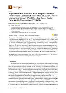
Progress In Electromagnetics Research, Vol. 112, 183–197, 2011
TRANSIENT RESPONSE CHARACTERIZATION OF THE HIGH-SPEED INTERCONNECTION RLCG-MODEL FOR THE SIGNAL INTEGRITY ANALYSIS T. Eudes, B. Ravelo, and A. Louis IRSEEM, EA 4353, Engineering School ESIGELEC Technopole de Madrillet Avenue Galil´ee, BP 10024 76801 Saint-Etienne-du-Rouvray Cedex, France Abstract—This paper is devoted on the characterization method of RF/digital PCB interconnections for the prediction of the highspeed signal transient responses. The introduced method is based on the use of the interconnection line RLCG-model. Theoretical formulae enabling the extraction of the electrical per-unit length parameters R, L, C and G in function of the interconnection line physical characteristics (width, length, metal conductivity, dielectric permittivity . . . ) are established. Then, by considering the second order approximation of the interconnection RLCG-model transfer matrix, the calculation process of the transient responses from the interconnection system transfer function is originally established. To demonstrate the relevance of the proposed model, microwavedigital interconnection structure comprised of millimetre microstrip line driven and loaded by logic gates which are respectively modelled by their input and output impedances was considered. Then, comparisons between the SPICE-computation results and those obtained from the proposed analytical model implemented in Matlab were made. As results, by considering a periodical square microwave-digital excitation signal with 2 Gbits/s rate, transient responses which are very wellcorrelated to the SPICE-results and showing the degradation of the tested signal fidelity are observed. The numerical computations confirm that the proposed modelling method enables also to evaluate accurately the transient signal parameters as the rise-/fall-times and the 50% propagation delay in very less computation time. For this reason, this analytical-numerical modelling method is potentially interesting for the analysis of the signal integrity which propagates Received 18 November 2010, Accepted 9 December 2010, Scheduled 12 January 2011 Corresponding author: Blaise Ravelo (
[email protected]).
184
Eudes, Ravelo, and Louis
in the high-speed complex interconnection systems as the clock tree distribution networks. In the continuation of this work, we would like to apply the proposed modelling process for the enhancement of signal quality degraded by the RF/digital circuit board interconnection where the signal delays and losses became considerably critical. 1. INTRODUCTION The last century was particularly remarkable with the spectacular progress of the microelectronic semiconductor industries which was till now, unique in the mankind history. These constant technological progresses are nowadays a source of innovative product developments in numerous civil sectors as the mobile phones, multimedia systems, medical equipments and even vehicles. As an undeniable quantification of this industrial development, according to Moore’s law prediction, at each generation the size of electronic printed circuit board (PCB) is reduced of 30% and every two or three years, the number of the transistors integrated in the microelectronic chips must be increased of four times [1]. Despite this fascinating scenario of technological development, the structures of the current interconnection circuitry between the logic gates, electronic chips and digital devices, and even the buses linking the different electronic boards as seen in Fig. 1 become more and more complicated [2–7].
Figure 1. High speed digital PCB. Furthermore, due to the incessant increase of the operating frequencies and the integration density, the contributions of the interconnection electric parameters as the resistance, capacitance and inductance effects [8–15] cannot presently be neglected by the electronic equipment manufacturers. Indeed, the signal integrity which represents the numerical-/digital-data is not preserved especially for the high-rate communication. This signal degradation effect needs to be taken into account by the electronic designers during the manufacture processes of the high-speed electronic devices. For this
Progress In Electromagnetics Research, Vol. 112, 2011
185
reason, different characterization techniques of the interconnection transmission line (TL) based on the S-parameter extractions were introduced since two decades ago [16–21]. In this optic, performance optimization methods dedicated to the clock tree distribution networks were proposed [22–24] in order to minimize the undesired influences of interconnection systems notably for the VLSI circuits. In addition, a compensation technique based on the insertion of repeaters between the piece of TLs was also proposed [11, 25] in order to reduce the TL interconnection negative effects. As improvement of this interconnection compensation technique, an alternative solution based on the use of negative group delay (NGD) circuits is introduced in [26, 27]. Notwithstanding these various technical solutions, further simpler, faster and more accurate methods need to be developed to model the interconnection line effects especially for the complex circuitry especially, in transient domain. One underlines that most of existing characterization methods were developed only in frequency domain by using the S-parameter characterization deduced from the geometrical parameters (width, length, substrate height) of the TL and the electromagnetic properties (dielectric permittivity and metal resistivity) [16–20, 28]. Whereas the existing time-domain characterization methods are usually based on the use of the classical RC- or RLC-transfer function models [8–15, 29]. So, more complete modelling method is still necessary for the estimation of the transient response induced by the interconnection TLs particularly for the highspeed digital- and/or mixed-electronic systems. This statement motivates us to suggest and to develop further modelling process allowing to forecast simply the influences of RF/digital interconnection circuitries on the signal quality via the analysis of the transient response behaviours. To make this paper more understandable, the theoretic analysis highlighting the determination of the microstrip TL high frequency parameters as the characteristic impedance and constant propagation from the geometrical (width, length, substrate height) and physical (dielectric permittivity and metal resistivity) characteristics is recalled in Section 2. Then, the calculation method enabling the extraction of the RLCG-model per unit length parameters is equally presented. Hence, mathematical analysis explaining the determination of the linear transfer function enabling to express the interconnection transient responses is offered in Section 3. Hence, discussions on validation results based on the comparison with standard electronic simulation tool SPICE results are the object of Section 4. Finally, the last Section is the conclusion of the paper.
186
Eudes, Ravelo, and Louis
2. EXTRACTION OF THE MICROSTRIP LINE RLCG-PARAMETERS For starting let us consider the microstrip TL with geometrical length d, width w, metallisation thickness t as depicted in Fig. 2. One assumes that the dielectric substrate is characterized by its height h, relative permittivity εr and loss constant tan(δ).
d
t y z x
h
W
Figure 2. Geometrical representation of microstrip TL. The corresponding characteristic impedance Zc and the propagation constant γ(f ) = α(f )+j ·β(f ) can be deduced from these physical properties according to the formulations reported in [16, 17, 32] as expressed in (1) and (3). " # r h · a(w/h) 4h2 η0 ln + 1+ 2 , (1) Zc = √ 2π εeff w w where
" µ # ¶ 30.66h 0.7528 a(w/h) = 6 + (2π − 6) · exp − , w
(2)
with η0 is the air impedance and εeff is the effective permittivity of the medium. One points out that as reported in [32], by denoting c is the speed of light in the vacuum, the constant propagation: 2πf p γ (f ) = αc (f ) + αd (f ) + j εr (f ), (3) c includes the metallic conductor and the dielectric losses respectively given by: ¡ ¢2 ½ · µ ¶¸¾ 32− wh h 1 2h Rs (f ) αc (f ) = 1.38 · 1+ · 1+ · ln · · ¡ ¢ , (4) weff π t h · Zc (f ) 32+ w 2 h εeff − 1 tan(δ) εr · √ · 2πf , (5) αd (f ) = 27.3 εr − 1 εeff c
Progress In Electromagnetics Research, Vol. 112, 2011
Luδ x
R uδ x
C uδ x
R uδ x
Luδ x
C uδ x
G uδ x
δx
187
G uδ x
δx
Figure 3. TL RLCG-model. with Rs (f ) =
p
π · µ0 · ρ · f , (6) £ ¡ 2h ¢¤ 1 1.25 w w + π £1 + ln ¡ t ¢¤, if h < 2π weff = (7) 1 . w + 1.25 1 + ln 4πw , if wh ≥ 2π π t For the calculations including the radiating loss, more explicit analytical expressions of the propagation constant real part or the per unit length loss constant α(f ) are presented in [30–33]. Knowing Zc and γ(f ), one can extract the equivalent TL RLCG-model with the per unit-length parameters Ru , Lu , Cu and Gu as described in Fig. 3. As established in [28], the TL global parameters R = Ru · d, L = Lu · d, C = Cu · d, and G = Gu · d can be calculated with the following expressions: R = < [γ(f ) · Zc ] , (8) = [γ(f ) · Zc ] L= , (9) h ωi ½
C=
=
γ(f ) Zc
, (10) ·ω ¸ γ(f ) G=< , (11) Zc where