University of Illinois ... cess networks users contend for a single shared channel when they have a ... a shared wireless channel network, it is highly desirable.
Transmission Power Control for Multiple Access Wireless Packet Networks Jeffrey P. Monks, Vaduvur Bharghavan, and Wen-mei W. Hwu Center for Reliable and High-Performance Computing University of Illinois Urbana-Champaign, IL 61801 Email: {jmonks, bharghav, hwu}@crhc.uiuc.edu Abstract Multiple access-based collision avoidance MAC protocols have typically used fixed transmission power, and have not considered power control mechanisms based on the distance of the transmitter and receiver in order to improve spatial channel reuse. In this paper, we motivate transmission power control and investigate the challenges involved in implementing power control in multiple access wireless packet networks. For this work, we focus on wireless ad-hoc networks, where the links connecting sourcedestination pairs are all wireless. Power control has been implemented in cellular networks such as CDMA (code division multiple access) for quite some time now. However, these protocols depend on centralized control (i.e. base stations) and duplex communications that are not inherently present in wireless multiple access packet networks. Our simulation results show that implementing power control in a multiple access environment can improve the throughput performance of the non-power controlled IEEE 802.11 by a factor of 2, thus providing a compelling reason for migrating to a new power controlled multiple access wireless MAC protocol standard.
1 Introduction One of the major issues in wireless networks is developing efficient multiple access protocols. Wireless networks have scarce resources (fixed bandwidth shared among many users and limited power reserves) compared to wired networks. In recent years, transmission power control has been used to more fully exploit the available resources in the wireless environment by increasing spectral reuse. Past work on power control has primarily dealt with cellular networks with inherent duplex communications (where separate frequency bands are typically allocated for forward and reverse channels), making it possible for receivers to place transmission power adjustment requests into outgoing data [1, 2]. However, this work concentrates on wireless adhoc packet networks (which we will generally refer to
as just multiple access networks), where all data packets are sent on a single shared channel. In this type of system, there is no centralized control and the links are simplex. In a cellular network each user is granted a separate channel to send its data, while in multiple access networks users contend for a single shared channel when they have a packet to send, making transmission power control significantly more complex. This paper presents an investigation on the issues involved in providing a power controlled MAC for multiple access networks. The goal of this paper is not to describe a specific power controlled protocol, but rather to motivate (based on performance gains) and investigate a basic framework for power control for multiple access networks. In cellular networks such as CDMA, power control reduces the aggregate background noise from other users (partly correlated to the specific user’s signal), resulting in an increase in the signal to interference ratio (SIR). Therefore, allowing a greater number of mobiles to be introduced into the system. Power control in multiple access environments reduces the interference range, allowing for a more tight spatial packing of source-destination pairs. In multiple access environments the user signals are perfectly correlated (since all users occupy the same channel) so a single transmitter can more easily corrupt another users incoming packet. This means that transmitters must bound their signal power according to the constraints (noise tolerance) of the receiver most easily corrupted by their transmission. We can further conclude from this that even small changes in link gain (between source and destination or other transmitters and a receiver) can significantly alter the quality of an incoming signal. In summary, in cellular networks the background noise level dictates whether or not a node may send data, while in multiple access networks the location of exposed receivers dictates whether or not a station may send data. Wireless MAC protocols have made the case that a sender-receiver pair should first “acquire the floor” before initiating a data packet transmission. Acquiring the floor allows the sender-receiver pair to avoid collisions
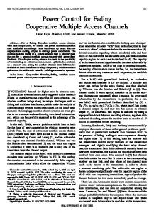
due to hidden and exposed stations, which may result in shared channel wireless networks (Figure 1 illustrates the scenario). The protocol mechanism that is used to achieve such collision avoidance typically involves preceding a data packet transmission with the exchange of a RTS/CTS (request-to-send/clear-to-send) control packet handshake between the sender and receiver. This handshake causes any station that either hears (i.e. correctly receives) a control packet or senses a busy carrier to defer its own transmissions while the ongoing data transmission is in progress (as shown in Figure 1). In the last decade, a significant amount of research has gone into the design and improvement of collision avoidance protocols [3, 4, 5, 6], culminating in the widespread adoption of the IEEE 802.11 MAC protocol standard by the dominant wireless LAN manufacturers.
B
A
C
neighbors, but only a few people may be heard clearly at any time if each speaker starts to shout instead of whispering (Figure 2 illustrates the scenario). Unfortunately, it turns out that for the collision avoidance mechanisms considered above to work correctly, the control and data packets must be transmitted with a fixed power in order to preserve the assumption of “commutativity of transmission”, i.e. if A hears B then B hears A [4]. This is because during an RTS/CTS exchange, the CTS sent by the receiver must reach all transmitters (e.g. hidden stations) whose control and/or data packet transmissions may potentially collide with the anticipated data reception at the receiver. From this requirement, it is easy to reason that all control and data packets will need to be transmitted at the same fixed power. The undesirable consequence of this characteristic is that a transmitterreceiver pair cannot adaptively change the amount of the floor it acquires depending on how close the transmitter and receiver are to each other. To the best of our knowledge, most of the existing work on multiple access wireless MAC protocols uses the fixed power assumption. Theoretical studies have shown that MAC protocols with optimal power control can improve the spatial √ channel reuse by a factor of O( η) over MAC protocols without power control, where η is the density of nodes in the region (using fluid model approximations) [7]. While the precise result quoted above makes a number of simplifying assumptions about the network characteristics, it does point to the fact that wireless MAC protocols with power control can significantly improve the throughput performance by overcoming the fundamental commutativity assumption of existing collision avoidance protocols.
D
Time RTS CTS Data
ACK
Figure 1: General Protocol Operation for Multiple Access with Collision Avoidance. The top part of the figure shows four wireless nodes which have a transmission range shown by the dashed ellipses. B is the sender, C is the receiver, A is the exposed station (within range of sender but not receiver) and D is the hidden station (within range of receiver but not sender). Note that during a successful B-C transmission, D must not transmit. When B wants to send a data packet to C, it senses the channel to see if it is free. Then B sends RTS to C. If A hears the RTS, it defers till B can hear C’s CTS. If C is free to receive, it sends back a CTS to B. When D hears the CTS, it defers transmission till B finishes sending data to C. When A hears busy carrier, it defers transmission. After C receives the data packet correctly, it sends back an ACK to B. This is the ideal operation of the protocol.
H E
F
A
B
C D I
G
While acquiring the floor to enable collision avoidance from hidden and exposed stations is certainly a fundamental requirement for the efficient operation of wireless medium access, it does preclude multiple concurrent transmissions over the region of the acquired floor. Thus, in order to optimize spatial channel reuse in a shared wireless channel network, it is highly desirable that a pair of communicating nodes only acquires the minimum area of the floor that is needed for it to successfully complete a data transmission. Considering a simple analogy, many people in a crowded party can potentially converse simultaneously by whispering to their
Figure 2:
Motivation for Power Control in Collision Avoidance-based Medium Access. For the given placement of nodes, in a traditional collision avoidance-based MAC protocol, if B is sending to A then D could not send to C since C would hear the RTS from B and sense the ongoing transmission. However, if B reduced its transmission power such that it would be just enough for B to capture its signal then other nodes in the region (e.g. D) could also proceed with their transmission. Such a protocol would allow for a tighter packing of source destination pairs within a network environment, thereby improving the spectral reuse.
2
Motivated by these anticipated performance gains (and corresponding reductions in battery power consumption), the goal of this work is to investigate the issues involved in providing a power controlled multiple access wireless MAC protocol within the general collision avoidance framework. We now deduce two basic principles for implementing power control in wireless networks: (a) the power conserving principle dictates that each station must transmit at the minimum power level that is required to be successfully heard by its intended receiver under current network conditions, and (b) the cooperation principle dictates that no station that commences a new transmission can transmit with enough power to disrupt ongoing transmissions. Cellular networks follow the first principle by having the receiver measure the quality of service (SIR) of its incoming signal and injecting an increase or decrease transmission power request into its outgoing data. In multiple access networks there is no explicit feedback channel since there is typically only a single shared channel. The cooperation principle is implemented in cellular networks by blocking new transmitters when there admission will make the system infeasible [1, 8, 2]. This is typically either decided at the base station by checking the background noise level and deciding if it is above some upper bound or at the mobile station by injecting a small test power signal into the network and checking if the change in noise power (due to other stations increasing their transmission power as a result of the test signal power) is greater than that injected. However, in multiple access networks we cannot assume the presence of a base station to regulate node transmissions. Also since communications between source and destination are uniplex and require contention, feedback would at best be significantly delayed under high loads such that new stations would have to delay a significant period of time to determine if their admission is feasible. Besides cellular networks, other work investigated power control (and spreading gain control) to provide differentiated service to real-time and nonreal-time users [9, 10], but this is over a multichannel CDMA link. Transmission power adjustments for controlling the topology in shared channel multihop networks was investigated in [11], where the authors present heuristics that adaptively adjust a node’s transmission power in response to topological changes and attempts to maintain a connected topology using minimum power. However, this method does not specify a mechanism to discover link gains between source-destination pairs nor does it define how the transmission power can be managed to avoid and resolve collisions. Rather, it assumes this functionality is already provided by some lower layer propagation function. The transmission power levels
for asymptotic connectivity and the theoretical capacity bounds for power controlled ad-hoc networks are demonstrated in [7]. Though it does not explore the implementation issues involved in providing such a mechanism. The rest of the paper is organized as follows. Section 2 presents the channel model and power constraints needed to implement a power controlled wireless protocol. Section 3 investigates the implementation issues of power control in various environments. In Section 4, an ideal power controlled protocol is compared to IEEE 802.11 with an implementation in the ns2 wireless network simulator. Finally, Section 5 summarizes key results and issues.
2 The network and channel models As in IEEE 802.11 and other multiple access protocols [3, 4, 5, 6, 12], we assume a shared channel model in which simultaneous transmissions in the neighborhood of the receiver will result in a collision at the receiver. In a spread spectrum physical layer environment, this model corresponds to medium access among a group of nodes that have the same frequency hopping pattern in Frequency Hopping Spread Spectrum, or the same pseudo-random sequence number in Direct Sequence Spread Spectrum. At the MAC layer, we do not assume a cellular model, and we do not constrain designated “base stations” to be senders or receivers of data. Thus in contrast to most previous work on power controlled MAC protocols that happen to be tailored to cellular environments, this work is applicable to both cellular and ad hoc network environments. In the rest of this section, we first describe the channel propagation model, and then describe the transmission power constraints that must be satisfied by each node in the shared channel network such that the physical capabilities of each transmitter, the power conserving principle, and the cooperative principle are not violated.
2.1 Channel propagation models We now describe the channel propagation model that we assume for a typical wireless channel. While our focus is on the MAC layer rather than the physical layer, we have taken into account the channel propagation characteristics at a sufficient level of detail for a power controlled MAC to work reasonably well in practice. The amount of spatial reuse and transmission power required for a node to send a valid signal to its destination will depend on the gain between each source and destination, which models the attenuation of the transmitter power over distance. Let Gij be the gain between a source i and a destination j. We define two path loss field regions: the region where the gain drops proportional to the distance squared (inside the Fresnel zone) 3
and refer to it simply as the 1/d2 field and the region (outside of the Fresnel zone or beyond the cross-over distance) where the gain is proportional to the distance to the fourth power and refer to it as the 1/d4 field. In the 1/d2 field the gain is proportional to 1/d2 ; however, we concentrate on the field since this is where the greatest degree of spatial reuse is exploited. The gain in the 1/d4 field is sometimes modeled as the 2-ray ground reflection model [13, 14, 15] Gij =
A , dα ij
In a power controlled multiple access implementation the gain would need to be measured from an incoming signal. The fast fading channel effect can distort this measurement over time such that the measured value may vary from that actually observed in the transmission.
2.2 Power constraints Let P t M ax and P t M in denote the maximum and minimum transmission powers for a transmitter on the data channel, respectively. Let RX T hresh and CS T hresh denote the minimum received signal power for receiving a valid packet and for sending the carrier, respectively. Let SIR T hresh denote the “capture threshold”, i.e. the minimum signal to interference ratio for which the receiver can successfully receive a packet. Given the transmitter and receiver power parameters and the channel propagation characteristics, a transmitter i must transmit a packet to a receiver j at the minimum transmission power P ti that satisfies the following power constraints.
(1)
where A is a constant that accounts for the signal strength gains from the transmitter and receiver antennas and their heights, dij is the distance between nodes i and j, and α is the path loss exponent (where α = 4 is the value typical chosen). This is also the model used for the CMU mobile extensions to the ns2 simulator [16]. While this model is appropriate for flat and open areas, objects in the path between a transmitter and receiver may introduce additional interference such as shadowing [13, 14, 15], which results in a log normal contribution to the gain to produce a slow fading model Gij =
A ζ/10 10 , dα ij
1. The transmission power of i must be within its parameter range, P t M in ≤ P ti ≤ P t M ax.
(2)
2. The received power at j must at least equal its minimum threshold, Gij P ti ≥ RX T hresh.
which is referred to as log normal shadowing. In addition to shadowing, the signals may follow multiple paths (each with independent shadowing), from the transmitter to receiver. Each path will have an amplitude component that is Rayleigh distributed (also called the fast fading component) and a uniformally distributed complex phase (i.e. r exp(jΘ), where r is Rayleigh distributed and (is uniformally distributed) [13, 14, 15, 17]. If we look at an M-ray Rayleigh fading model, the resulting gain is then
3. The observed signal to noise ratio for the transmission at j must at least equal its minimum threshold. G Pt SIRj = Pijnj i ≥ SIR T hresh, where P nj is the total noise that node j observes on the data channel and is defined as X P nj = Glj P tl + Nj (5) l6=i
Gij = |
M X
A
(ρ)α ρ=1 dij
10ζρ /10 rρ ejΘρ δ(t − τρ )|,
The term Nj is the power of the thermal noise (the power observed at a receiver when no nodes are transmitting) observed at node j.
(3)
(ρ)
where dij is the distances between nodes i and j following path ρ and ζρ , rρ , and Θρ are random variables representing the shadowing, Rayleigh amplitude, and phase angles, respectively, for each path paths. The mean values of {rρ }M 1 are usually set such that v uM uX t r 2ρ = 1, (4)
4. Let Ek be the “noise tolerance” of any receiver k that is receiving an ongoing transmission in the neighborhood of i. Ek is thus the additional noise power that k (currently receiving data from some other node at power P rk can tolerate before its SIR drops below its SIR T hresh, and is defined as
ρ=1
Ek =
the combination of the squared average Rayleigh amplitudes are normalized to one. In other words, over the long term the fast fading components will result in a uniform gain contribution.
P rk − P nk . SIR T hresh
(6)
Since the transmission power of i should not disrupt any ongoing transmission, P ti ≤ min{ GEiki } = P t boundi . 4
If the above four constraints can be met, then i can successfully transmit to j without disrupting any ongoing transmissions. The critical problems therefore are (a) handshaking between a transmitter-receiver pair to determine the minimum transmission power that satisfies constraints 2 and 3 (i.e. the power conserving principle), and (b) for every receiver to advertise its noise tolerance so that no potential transmitter will disrupt its ongoing reception using constraint 4 (i.e. the cooperative principle).
that the bandwidth efficiency is kept high). In addition, the channel gain may be different in the two separate physical channels causing the power calculations based on measurements from the control channel to be different from that needed on the data channel. Method 3 has a higher channel efficiency and increases the accuracy of the power calculations by using a single channel for control and data, however, if control packets collide then the source will assume the destination is out of range and backoff longer than necessary. Before a new station can transmit it must be made aware of the sensitivity (noise tolerance) of other stations to its transmission power. We now investigate two mechanisms for limiting the amount of injected interference by other transmitters to satisfy the cooperative principle (constraint 4).
3 Implementation issues In this section, we discuss the pertinent issues relating to the design and implementation of a power controlled MAC. Given the network and channel models defined in Section 2, we start by considering various implementations that satisfy the network constraints. Then we investigate the tradeoffs involved in channel placement and finally, how different channels characteristics (discussed in Section 2.1) affect system performance. Here we investigate the tradeoffs involved in choosing three possible mechanisms for determining the necessary transmission power to satisfy the destination (constraints 2 and 3, the power conserving principle).
A. Receivers send broadcast messages containing the noise tolerance at some predetermined power level (such that the gain can be determined from the received power level measured at a transmitter) greater than the maximum power level of a data signal (such that all potential interferers can “hear” the message). The noise tolerance and gain measurement can then be used in conjunction to bound the transmitter’s power.
1. The source sends at an initial power level and changes its transmission power based on feedback messages requesting an increase or decrease in transmission power (similar to a cellular implementation [1, 8, 2]).
B. Broadcast power signals are sent by the receiver, where the power level is inversely proportional to the receiver’s noise tolerance level. That is the receiver “yells” louder the received power approaches the its lower bound (power level for receiving a valid signal). Then the louder a potential transmitter “hears” the power signal, the less power it is permitted to transmit.
2. Use control messages on a separate channel to determine the necessary transmission power to reach the destination and over compensating by sending with more power than required. The additional transmission power provides a tolerance range.
In both methods, the noise tolerance advertised by the receivers must be sent on a separate channel from the data to avoid collisions with hidden stations. This means the gain in the data and noise tolerance advertisement (NTA) channels will differ causing the noise advertisement to differ by some degree from the true noise tolerance. The amount that they differ will depend on the channel distortions (e.g. multipath) in the channels, channel spacing, and shape of signals. The disadvantage of method A is that it is contention based so the noise tolerance advertisements may be delayed significantly (depending on the network load) such that a new transmitter believes it can send at a greater transmission power than it is really allowed. Method B has the advantage that it is not delayed based on the contention, however, additional mechanisms must be added to avoid collisions of power signals from different receivers 1 .
3. This method is similar to the second except that it uses the data channel to send the control messages, but sends them at a power level slightly below that which will cause corruption at other receivers (see below discussion). If there is no response, then the source assumes the destination requires more power than it can currently send without interfering with another transmission and backs off. In multiple access networks, where the channel access is shared, contention can cause significant packet delays under heavy loads. This will reduce the performance of Method 1 since the power adjustments will not be received in time and these packets will add to the network congestion. In Method 2, allocating a separate channel to determine the needed transmission power will reduce the channel efficiency because the data will need to wait for information to be sent on a potentially slower control channel (since less bandwidth would be allocated so
1 Note we cannot reuse the control channel proposed for Method 2 above because the transmission power must be varied according to a receiver’s noise tolerance.
5
3.1 Channel placement
this requires only one bit of redundancy for each erasure to be corrected. This does however, impose a constraint on the number of NTA that the receiver can send and therefore, the number of noise tolerance updates during a packet interval. If the NTA can be quickly acquired (on the order of one bit) by potential transmitters then there will be little additional overhead and method (iii) would be most favorable. Otherwise, method (i) would be the preferred method.
To ensure that the gain on the data and NTA channels are similar, the out of band channel frequency components must be within the coherence bandwidth of the data channel. The coherence bandwidth is inversely proportional to the multipath delay spread, which may vary greatly depending on the environment. In many outdoor environments the delay spread can be greater than 1 us resulting in a coherence bandwidth of less than 1 MHz [13] [14] [15] [18]. However, there are also minimal channel spacing constraints imposed as a result of the protocol requiring the noise tolerance to be transmitted from receivers at the same time as the data is received. If we look at a typical cellular systems (e.g. AMPS, GSM, and CDMA) [13] the fractional bandwidth is usually at least 3% (i.e. carrier frequency spacing/carrier frequency ≥ .03) to ensure the outgoing signal does not deafen the incoming signal. This is necessary because small impedance mismatches between the duplexer and antenna causes part of the outgoing signal energy to be reflected back into the receiver. To keep the cost of components down the input filter has a gradual cutoff passing some energy in the near bands so there must be a significant spacing between output and input frequencies. If we then consider a 1 GHz data carrier, this would mean the frequency spacing between data and noise tolerance channels should be around 30 MHz if the receiver is to avoid the outgoing signal from interfering with the incoming signal (placing it outside of the coherence band). Based on the above discussion, consider three possible channel designs: (i) place the NTA channel outside the coherence band of the data channel and assume the difference in gain can be over compensated for, (ii) require the transmitter to periodically leave a gap in the data during which the receiver sends the NTA, or (iii) allow the NTA channel to periodically deafen the data channel and assume the data channel has enough redundancy to overcome any losses incurred. If method (i) is implemented the gain on the NTA and data channels may be vary substantially. An additional problem is that this method requires allocating noncontiguous bandwidth which may not be very attractive to system designers. Method (ii) requires that the transmitter estimate the times at which the receiver may need to send the NTA, while method (iii) requires the transmitter to estimate only the number of NTA transmissions needed and not their locations. An additional attraction of method (iii) is that the receiver knows the bit positions that may be corrupted by the NTA transmission. As a result, we can substitute these bits with erasures before passing the code through the decoder. For the most efficient codes (i.e. maximum-distance (MDS) like the Read-Solomon code [19] used most cellular networks)
3.2 Channel effects For the simple path loss model (based on distance and shadowing) the fading (i.e. gain) is similar in both directions since both directions see the same paths and interfering objects. However, for more complicated models (with multipath effects) the Rayleigh components will be different in each direct. In addition, Rayleigh fading is often classified as fast fading because it causes gain variations from one sample to the next. Therefore, some additional over compensation (on the order of the Rayleigh fading amplitude) is required to overcome the Rayleigh fade. In environments with extreme Rayleigh fading the performance of the power control methods would be significantly degraded since the necessary over compensation would prevent most nodes from sending at all. Though as noted in Section 1 the performance of current non-power controlled methods would also degraded since the carrier sensing mechanisms and RTS/CTS collision avoidance assume if I can hear you, you can hear me. However, in environments with modest Rayleigh fading the protocol will be able to compensate for the degrading factors and therefore, result in a significant improvement over other non-power controlled protocols. In this section, three methods where discussed for determining the necessary transmission power and two for regulating the transmission power needed to protect ongoing packet receptions. The tradeoffs involved in placing a noise tolerance advertisement channel where investigated, and the performance degradations due to various channel effects where evaluated. The goal of this section was not to define a specific implementation, but rather investigate the tradeoffs involved in implementing the mechanisms (gain computation and transmission power bound) necessary for a power controlled MAC in a multiple access environment with varying channel effects.
4 Analysis In this section, we investigate the potential improvements of a power controlled MAC protocol over the current standard IEEE 802.11. This section uses a a wireless network simulation to evaluate the performance of both protocols. 6
In order to explore the capacity enhancements of a power controlled MAC protocol without limiting our scope to a specific protocol, we define an ideal power controlled (IPC) MAC protocol. The IPC protocol has perfect (global) knowledge of the link gain between any two nodes, the noise at any potential destination, and the upper bound on a transmitter’s signal power needed to protect other receivers (maximum transmission power that neighboring receivers can tolerate). The IPC protocol though not real protocol since it assumes global knowledge allows us to demonstrate the capacity a power controlled MAC protocol that has specified mechanisms for obtaining these parameters. For the simulations nodes were uniformally distributed in a 1000 by 1000 meter network. However, the nodes did not move throughout the simulation because IPC has perfect global knowledge and we do not want to introduce factors that will only add overhead to 802.11. The routing overhead was removed (since the goal of this paper is to evaluate the performance of MAC protocols and not routing protocols) by determining the routes off-line such that the number of hops between source and destination was minimized.
Parameter Type Packet Size Data rate Channel carrier frequency RTS CTS, ACK Max retransmissions SIR Thresh SIR Desired CS Thresh RX Thresh RX Desired Noise Floor Path Loss Exponent Pt min Pt max Pt Path loss exponent (α) Total antenna gain (A)
Parameter Value 2 KB 2 Mbps 916 MHz 20 Bytes 14 Bytes 4 6 dB 10 dB -78 dBm -64 dBm -60 dBm -104 dBm 4 -7.5 dBm 28.5 dBm 24.5 dBm 4 1.5
Table 1: Simulation parameter settings
The IPC protocol follows the power conserving principle by reducing the transmission power to be only slightly more than is needed to reach the intended destination and the cooperation principle by backing off if the needed power is greater than the transmission power bound. The protocol like IEEE 802.11 follows the RTSCTS-DATA-ACK exchange, however, all messages are sent with only enough power needed to reach the destination. A source in IPC will set its network allocation vector (NAV) [5] if it hears an RTS or CTS from another source destination pair. However, the transmission powers are not constant so we can no assume if I can hear you, you can hear me (as does IEEE 802.11), which is why the transmitter uses an upper power bound to limit its transmission power when the RTS/CTS are too quiet to be heard. IPC does not make power adjustments throughout the transmission since this is not only difficult to simulate, but is also not practical to implement in a real multiple access system, as discussed in Section 3. The protocol instead starts by sending Comp T hresh (the difference between SIR Desired and SIR T hresh or RX Desired and RX T hresh) more power (in dB) than is required by the receiver’s constraints, allowing some degree of noise tolerance. In our simulation, the value of Comp T hresh is set offline, however, it can be chanced dynamically based on environmental (channel) effects as discussed Section 3. IPC was implemented in ns2 (a commonly used network simulator) and integrated into the CMU wireless extensions [16] to obtain the results demonstrated in this section.
IPC and 802.11 are tested under various network configurations, node densities, and traffic patterns. The parameter values used in the simulation are shown in Table 1. Here IPC can send at a minimum power of -7.5 dBm and a maximum power of 28.5 dBm, and 802.11 sends at a fixed power of 24.5 dBm. The maximum power of IPC is set to be 4 dB above the fixed power of 802.11 so that a destination at maximum transmission range for 802.11 will also be at maximum transmission range for IPC allowing for a 4 dB compensation in transmission power. This allows the same scenario files that determine the node connectivity to be used for both protocols. These parameters are reasonable and correspond to settings in the hardware of a commercial wireless vendor. For the figures demonstrating the one hop performance (Figures 3, 4, and 5), the throughput is normalized (to form the channel utilization with respect to 802.11) to the carrier sense range (i.e. 550 m) and the slot time such that the number of arrivals or departures is divided by a scaling factor, sf, defined as follows sf =
1 network area . carrier range area data slot size
(7)
For a 1000 by 1000 meter network with the parameter settings in Table 1, the resulting scaling factor is then 2 1 sf = 1000 5502 .008 = 413.22. We now present our results and compare the performance of IPC to 802.11. Our traffic model is simple: sources generate arrivals according to independent Poisson processes. The source node is picked randomly 7
from the set of all nodes and the destination is picked randomly from the set of all nodes one hop away (in transmission range). Each data transmission between source and generation will be referred to as a flow, and each flow will have a specified rate that refers to the number of packets sent per second. Figure 3 shows the network utilization for both IPC and 802.11 for varying packet transmission rates per flow. The figure demonstrates that a power controlled protocol (following the guidelines of IPC) can result in a significant improvement in throughput over 802.11. Note that the utilization of IPC surpasses 100 %. This is because the scaling factor, sf , includes a fixed transmission range (set to the carrier sensing range of 802.11, 550 m), where a power controlled protocol will often send with significantly less power. For the channel model used in the simulation (2-ray ground reflection) the max transmission range (at max power) is 250 meters.
In Figure 3 the routing tables where setup off-line such that two nodes were considered directly connected (within one hop) if they where no more than 250 meters apart. We refer to this as the connectivity range. For Figures 4 and 5 the connectivity range was set to be 150 meters and 50 meters, respectively. Notice that as the connectivity range decreases the performance of IPC increases while 802.11 remains virtually the same. This demonstrates that as destinations nodes become more localized to their sources the performance of IPC increases because source-destination pairs can be packed tighter into the network area, increasing spatial reuse. However, 802.11 transmits with the same power (acquires the same “floor” size) regardless of the distance between source-destination pair so the performance will not scale as the locality increases. In summary, if source and destination nodes all happen to fall within a smaller range than the maximum transmission range, either due to physical movement constraints of the mobile user or due to placement of the network access points, power control protocols will observe even greater improvements in performance.
120
100 IPC 802.11
250
Utilization (%)
80
200 60 IPC 802.11
Utilization (%)
40
20
150
100
0
0
10
20
30 40 Flow Rate (packets/sec)
50
60
70 50
Figure 3: 100 nodes in a 1000x1000 meter network with 100 flows each sending 2 KB packets, 1 hop between source and destination, and a connectivity range of 250 meters
0
0
10
20
30 40 Flow Rate (packets/sec)
50
60
70
Figure 5: 100 nodes in a 1000x1000 meter network with 100 flows each sending 2 KB packets, 1 hop between source and destination, and a connectivity range of 50 meters
160
Notice from these figures that the performance of IPC continues to increase even under very high loads due to long range transmissions being blocked by the transmission power bound allowing a greater number of short range transmissions. As the network load increases, the probability of a node requiring more power than the transmission power bound (set by the cooperation principle) also increases. The expected power for a source to reach its destination will increase as the network load increases due to an increase in background noise, and the expected transmission power bound decreases as the network load increase because there will be an increases in the number of exposed receivers in the network. Then sources requiring more transmission powers (i.e. greater transmission ranges for a simple path loss channel) will
140 IPC 802.11
120
Utilization (%)
100
80
60
40
20
0
0
10
20
30 40 50 Flow Rate (packets/sec)
60
70
80
Figure 4: 100 nodes in a 1000x1000 meter network with 100 flows each sending 2 KB packets, 1 hop between source and destination, and a connectivity range of 150 meters 8
is changed under heavy loads more work is needed to investigate techniques that overcome the fairness implications for power controlled protocols.
0.4
0.35
0.25 0.4 0.2 0.35 0.15 0.3 0.1
Fraction Of Packets Sent To Range
Fraction Of Packets Sent To Range
0.3
100−1 100−4 100−16
0.05
0
100−64
0
50
100
150
200
250
Range (m)
0.25
0.2
100−1
0.15
100−4 100−16 0.1
Figure 6: 100 nodes implementing IPC in a 1000x1000 meter network with 100 flows each sending 2 KB packets, 1 hop between source and destination, and a connectivity range of 250 meters
100−64
0.05
0
0
50
100
150
200
250
Range (m)
Figure 7: 100 nodes implementing IEEE 802.11 in a 1000x1000 meter network with 100 flows each sending 2 KB packets, 1 hop between source and destination, and a connectivity range of 250 meters
be more likely to backoff allowing a greater number of short range transmissions. Therefore, a power controlled MAC operating in a multiple access environment will result in unfair favoritism toward source-destination pairs sending over shorter distances. This phenomenon is particularly evident over the 250 meter connectivity range for IPC as demonstrated in Figure 6, where the fraction of total packets received by destinations in five distance ranges (0-50, 50-100, 100-150, 150-200, and 200-250 meters) from their sources is shown for 100 flows sending 1, 4, 16, and 64 packets per second. A perfectly fair protocol would result in a linearly increasing number of packets sent to each range since the number of destinations within each range increases as 2πr, where r is the distance. Notice for a very lightly loaded transmission rate such as 1 the number of packets send at each range is linearly increasing. However, as the network load increases the ratio of packets send over a greater distance decreases, and for extreme loads we observe that the majority of connections are short range. The fraction of packets sent to each range for 802.11 is shown in Figure 7. The protocol also becomes less fair (sending fewer packets to greater ranges) as the load increase, but not to the extent that a power controlled protocol like IPC does. The 802.11 protocol has an equal probability of sending packets to destinations at any distance since the transmission power is not taken into account by the contention. However, because all transmissions are sent at a fixed power level there is less noise protection for destinations further from their sources resulting in a greater number of lost packets at greater network loads. IPC on the other hand, has the same amount of protection (the compensation factor) for destinations at all ranges, however, the probability of sending a packet to further destinations decreases as the network load increases, as described above. Whether additional compensation is used or the scheduling algorithm
The figures above demonstrated that for dense networks with spatial reuse to be exploited power controlled multiple access protocols have potential to performs significantly better than 802.11. For the one hop case a significant improvement results with IPC that scales as destinations become more local to the source. Further work is in progress to evaluate the performance of power controlled protocols over multiple hop wireless networks, which involves additional routing issues that are beyond the scope of this paper. These results demonstrate that there are compelling reasons for integrating power controlled protocols into ad-hoc networks.
5 Conclusion In this paper, we have motivated and investigated the issues involved in implementing a power controlled medium access protocol within the collision-avoidance multiple access framework. We have demonstrated that such a protocol can allow for a greater number of simultaneous senders than 802.11 by adapting the transmission ranges to the minimum value required to satisfy successful reception at the intended destination. We investigated the two basic principles involved in providing power control in wireless networks: power conserving principle and cooperation principle and demonstrate how they apply to multiple access networks to provide a basic framework for implementing power control. We believe that the pay-off for using a power controlled protocol is potentially large. We are currently working on a power controlled multiple access protocol, PCMA, that has mechanisms defined for determining the minimum transmission power and the upper bound on transmission power to prevent 9
interference with other receiving nodes. There is additional research in progress to investigate techniques for improving the fairness in a power controlled multiple access system, as well as performance under mobility and other design issues. Further work is also needed to evaluate the performance of power controlled protocols over a multiple hop wireless network. Notice there are additional issues involved in the multiple hop case since the routing protocol plays a major part in the overall performance. Our preliminary performance results show that a power controlled protocol can achieve a significant improvements in aggregate bandwidth compared to 802.11 for highly dense networks single hop networks and provide scalability in performance with increased node locality. These results lead us to believe that if engineered correctly, a power controlled multiple access protocol can achieve significant performance gains without compromising much on the robustness of power-unaware multiple access protocols, and hence provides a powerful motivation to migrate towards power-controlled MAC protocol standards.
[7] P. Gupta and P. Kumar, “The capacity of wireless networks,” IEEE Transactions on Information Theory, Nov. 1998. [8] J. Chuang and N. Sollenberger, “Uplink power control for tdma portable radio channels,” vtc, vol. 43, pp. 33–39, Feb. 1994. [9] J. Oh and K. Wasserman, “Optimality of greedy control in DS-CDMA mobile networks,” Mobicom ’99, 1999. [10] J. Oh and K. Wasserman, “Adaptive resource allocation in power constrained CDMA mobile networks,” IEEE Wireless Comun. and Networking Conf. (WCNC’99), 1999. [11] R. Ramanathan and R. Hain, “Topology control of multihop radio networks using transmit power adjustment,” Proc. IEEE Infocom, Mar. 2000. [12] J. Deng and Z. Haas, “Dual busy tone multiple access (dbtma): A new medium access control for packet radio networks,” IEEE ICUPC, pp. 973–7, 1998.
References
[13] T. Rappaport, Wireless Communications: Principles and Practice. New Jersey: Prentice Hall, 1996.
[1] N. Bambos, “Toward power-sensitive network architectures in wireless communications: Concepts, issues, and design aspects,” IEEE Personal Communications, vol. 5, pp. 50–59, June 1998.
[14] G. Stuber, Principles of Mobile Communications. Massachusetts: Kluwer Academic Publishers, 1996.
[2] F. Rashid-Farrokhi and et. al., “Downlink power control and base station assignment,” IEEE Communications Letters, vol. 1, pp. 102–104, July 1997.
[15] W. Jakes, Microwave Mobile Communications. New York: IEEE Press, 1974.
[3] P. Karn, “MACA - a new channel access method for packet radio,” ARRL/CRRL Amateur Radio 9th Computer Networking Conference, pp. 134–40, Sept. 1990.
[16] The CMU Monarch Project, “The cmu monarch mobility and wireless extensions to the ns-2 network simulator,” http://www.monarch.cs.cmu.edu/, Oct. 1999.
[4] V. Bharghavan, A. Demers, S. Shenker, and L. Zhang, “MACAW: A media access protocol for wireless lan’s,” Proceedings of ACM SIGCOMM ’94, vol. 24, pp. 212–25, Oct. 1994.
[17] B. Sklar, “Rayleigh fading channels in moible digital communications systems part ii: Mitigation,” Communications Magazine, pp. 103–9, July 1997. [18] J. Proakis, Digital Communications. New York: McGraw Hill, 1995.
[5] IEEE Standard 802.11, Information Technology– Telecommunications and Information Exchange Between Systems–Local and Metropolitan Area Networks–Specific Requirements–Part 11: Wireless LAN Medium Access Control (MAC) and Physical Layer (PHY) Specifications, 1997.
[19] R. Blahut, Algebraic Codes For Data Transmission. Urbana, IL: draft of book produced at The University of Illinois IEEE Student Branch, 1999.
[6] C. Fullmer and J. Garcia-Luna-Aceves, “Floor acquisition multiple access (FAMA) for packet-radio networks,” Proceedings of ACM SIGCOMM ’95, 1995. 10