image acquisition process and inputs of the user, two hard-drives to store the ... stereo tracking algorithm to recover the pose of the camera system for each.
Trinocular system for 3D motion and dense structure estimation Ricard Campos, Jordi Ferrer, Miquel Villanueva, Lluís Magí and Rafael García Computer Vision and Robotics Group, University of Girona, Spain Email: { rcampos, jferrerp, miki, llmagi, rafa}@eia.udg.edu
Abstract – The relief of the seafloor is an important source of data for many scientists. In this paper we present an optical system to deal with underwater 3D reconstruction. This system is formed by three cameras that take images synchronously in a constant frame rate scheme. We use the images taken by these cameras to compute dense 3D reconstructions. We use Bundle Adjustment to estimate the motion of the trinocular rig. Given the path followed by the system, we get a dense map of the observed scene by registering the different dense local reconstructions in a unique and bigger one. Keywords – 3D motion, 3D reconstruction, trinocular system.
I. INTRODUCTION Underwater images are a very rich source of data for scientists who study biological and geological processes of sea floor. Among other uses, underwater imagery can be used to construct image composites referred to as photo-mosaics. Photo-mosaics are widely used in many different study areas such as geological surveys, mapping and detection of temporal changes and autonomous vehicle navigation. Up to date, mosaicing has been carried out in 2D, providing a large two-dimensional composite image of the surveyed area. However, most of the regions of interest for the scientific community are located in areas with 3-dimentional relief. In this paper we present an optical system to model complex 3D objects of the ocean floor. This system will be the basis for automatic detection of changes in the morphology of many underwater objects in the future, allowing understating geologic, tectonic and sedimentologic processes in the seafloor. II. DESCRIPTION OF THE IMAGE ACQUISITION SYSTEM The image acquisition system, here after called trinocular system, is basically composed by three cameras, a processing unit (a standard PC) to control the image acquisition process and inputs of the user, two hard-drives to store the images and also a screen to give feedback to the user. All these elements are encapsulated inside four cylindrical steel containers: one for the processing unit and one for each camera. Given the poor lightning conditions of the underwater environment (due to light absorption and scattering) the selected cameras have a high light sensibility. As the purpose of the images taken by the system is to be used as input for a stereo reconstruction algorithm, we must ensure that the images are taken at the very same instant. In order to achieve this goal, we use the standard Parallel Port of the processing unit to simultaneously drive the three trigger signals and, by means of additional circuitry, we buffer and distribute these signals to the serial trigger port of their corresponding camera.
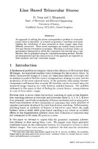
III. IMAGE PROCESSING In order to obtain a 3D reconstruction of the scene, we use a variant of the Match Propagation (MP) algorithm proposed by Quan et. al. in [1]. This algorithm uses a stereo pair of images and a set of initial seed matches between them to propagate the correspondences. This propagation is based on the assumption that the neighborhood around valid correspondences still shows sufficient texture to contain other reliable matches. To obtain a reliable set of seed correspondences, we use some of the well known algorithms for point detection, description and matching (like SIFT or SURF), followed by a RANSAC consistency check. Next, we apply a modified version of MP by performing a deeper search for each pair of points considered to be a good match. Instead of just accepting this correspondence we use the information of the third camera in order to verify whether the correspondence is also valid for the third view of that point. Epipolar geometry is used to efficiently locate the position of that point in the third image as the intersection of the epipolar lines coming from the location of that point in the first and second images. Once the MP algorithm is applied, the resulting set of correspondences is matched at subpixel level through interpolation. Afterwards, we apply a simple triangulation for each match to retrieve its 3D position. IV. CREATION OF A DENSE MAP In order to get all the reconstructions for each stereo set of frames, we use a stereo tracking algorithm to recover the pose of the camera system for each time instant over the sequence. In addition, we use a Sparse Bundle Adjustment method (based on [2]) to estimate the trajectory followed by the trinocular system. The cost function of the Sparse Bundle Adjustment minimizes the reprojection error of the tracked points. Having the path followed by the trinocular system and the dense local point clouds computed with the algorithm described section 3, we are able to register all these point clouds in a common reference system obtaining a dense map. This dense map is a unique and bigger dense reconstruction covering a larger area than the local ones. Figure 1 illustrates the preliminary results obtained in a non-underwater environment. V. CONCLUSIONS A new system for 3D modeling of the underwater sea-floor has been presented. We have developed a hardware system to acquire sequences of triplets of underwater images, and we have introduced a processing scheme to get an accurate dense 3D map from the captured set of images.
REFERENCES [1] M. Lhuillier and L. Quan. Match propagation for image-based modeling and rendering. IEEE Transactions on Pattern Analysis and Machine Intelligence, 24:2002, 2002. [2]M. I. A. Lourakis and A. A. Argyros. SBA: A Software Package for Generic Sparse Bundle Adjustment. ACM Transactions on Mathematical Software, 36(1):2:1-2:30, March 2009.
Fig. 1. Three views of a dense 3D map obtained from a set of local dense 3D reconstructions, where (a) is the plan, (b) the side view and (c) the main view.
45
Instrumentation Viewpoint 8
m4