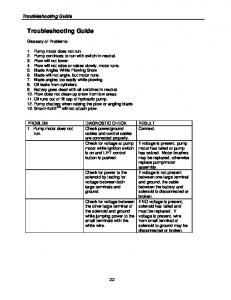
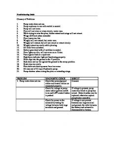
Additional Guidance on Tutorial Lesson 1: Parts. Sketching the ... You have to
exit the sketch before you can delete it, and the same for the feature. To delete ...
Additional Guidance on Tutorial Lesson 1: Parts
Sketching the Base If you don’t start with the “Boss” tool: The tutorial directs you to choose the extruded boss/base tool. If you don’t choose that, but end up just beginning a sketch, without selecting that tool, don’t worry, you can make an extruded boss from the sketch later, it will just require an extra step. You don’t have to start over. Deleting an error: If you make an error, and want to delete it, remember that you have to exit your current action before you can delete it. You can’t delete something that you are currently in the middle of an editing step on. You have to exit the sketch before you can delete it, and the same for the feature. To delete something, right-click on it in the design tree and select “delete.” If you choose the wrong plane: If you happen to select the wrong plane for the sketch, you have two solutions. One is to exit the sketch and delete it. The other is to complete the sketch normally. You can change the plane of a sketch after creating it by right clicking on it, and selecting “Edit Sketch Plane” from the options above the mouse cursor.
If you are trying to select a feature or reference from the design tree: IMPORTANT: When you are creating or editing a feature, and there are boxes for selecting a body, sketch, or plane, Solidworks
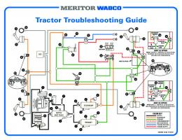
places a copy of the design tree in the graphics window, which you can expand in order to choose items from. If you end up changing the plane of a sketch, you will need to expand this design tree (check the “+” sign next to the name of the part in the top-left corner of the graphics area) and, with the Sketch Plane/Face box highlighted, select the desired plane from the tree. Ask a mentor for help if necessary. Sketch Problems Deleting unwanted sketch entities: One major frustration while beginning to make sketches in Solidworks is accidentally clicking the mouse button when you did not intend to, either placing the sketch in the wrong location or adding sketch entities that you did not want. If you add an unwanted sketch entity, activate the select tool by right-clicking and choosing it from the context menu. Select the undesired entities, and hit the delete key to remove them from the sketch.
Example of additional, unwanted rectangles and lines in a sketch. Preventing adding unwanted sketch entities: Make sure, while working through a project in Solidworks, as soon as you have finished with a sketch tool, to either right-click in the graphics window and choose the select option, or go to the toolbar and click on the sketch tool symbol, deactivating the sketch tool. You will know that the sketch tool has been deactivated because the pointer will change from a pencil with a picture of a sketch entity to a regular mouse icon. This will prevent accidently adding unwanted sketch entities.
Dimensioning the Base: If the cursor does not snap to the origin: For the purposes of the first step, make sure that you have the bottom left corner of the rectangle started at the origin. The tutorial describes how to accomplish this. If for some reason this does not work, draw the rectangle anyway, then go to the select tool, select the lower left hand corner, and drag it until it is over the origin – it should snap to the origin. If this still does not work, get help from a mentor.
Notes on Smart Dimension: Proceeding to step 2, use the smart dimension tool to define the rectangle. This should be easy, just select the sides of the rectangle. Follow the directions in the tutorial. If you happen to enter a number wrong, just double-click on the dimension to re-open the spin box and reenter the dimension. If you happen to select the wrong side, then just exit the smart dimension tool, by right-clicking the graphics window and choosing “select” or clicking the smart dimension tool in the toolbar to deselect it. Hitting the escape key also works. Then use the select tool to choose the
dimension, and hit the delete button to remove it. Note that if you try to put dimensions on opposing sides of the rectangles you will end up with an over-defined sketch – avoid this. Extruding the Base: If you have issues with selecting the right sketch: At this point the sketch is fully defined. Click the Exit Sketch button in the toolbar, in the top-right of the graphics area, or rightclick and choose it from the menu. If you didn’t select the boss-extrude tool at the first step, or if you somehow exit the bossextrude tool without creating the extrusion, go to the features tab of the toolbar, and select the Extruded Boss/Base tool. Since there’s only one sketch in the part so far, it should automatically select the sketch for you. When you’re dealing with multiple sketches in a part, you do have to be careful to make sure the right sketch is selected. If no sketch is selected, Solidworks will ask you to select the sketch – click on the sketch you want to extrude, in this case, the rectangle. If the wrong sketch is selected, find the dialog box which lists the selected sketches, and delete the wrong sketches from the box, making sure that the right sketch(es) is selected.
If you enter the wrong distance to extrude to: and exit the boss-extrude dialog without correcting it, go to the design tree, right-click on the extrude name, and find the “edit feature” button in the box of options that appears above the mouse. The dialog will reopen and you can edit the properties of the extrude.
If the extrude goes in the wrong direction: Make sure that the extrude goes in the right direction. When you create an extrude, a grey arrow/handle appears in the graphics window. Be sure that the arrow is pointing in the positive z direction. Check the origin triad in the lower right hand corner to see which directions are positive x, y, and z. If it is not pointing in the positive z direction, click the “flip directions” button next to the end condition menu in the feature manager. Sketching and Dimensioning the Boss: If you have trouble sketching on a face: The next part can be challenging. Again, if you place a sketch in the wrong place, either delete it, or use the select tool to relocate it to the correct place. It will help if you go to “Front View” of the part (Press Ctrl+1) and select the front face of the part before selecting the extruded boss too. If you select the wrong face to sketch on, then exit the sketch and try again – if exiting the sketch doesn’t remove it from the design tree, right-click on the sketch and delete it from the part. If you assign a smart-dimension to the wrong thing, go to the select tool, select it, and delete it. If you input an incorrect value for a dimension, use the select tool to double-click and edit it. If you exit a step, either a sketch or an extrude, without properly and correctly completing it, just select it in the design tree and select the “edit” option, and it will re-open. Extruding the Boss: Extrude in the right direction: The same thing applies here as for extruding the base – make sure the extrusion goes in the positive z direction for correct results.
Cutting/Extruding the Hole: When using an extruded cut to make a hole through the part:
If you have trouble making circles coincident: If you can’t seem to make the centerpoint of the sketched circle coincident with the centerpoint of the extruded circle, go to the select tool, select both the circle and the edge of the extruded cylinder, and under the properties tab, select the concentric tool. Ask a mentor for help if there is any confusion. If you aren’t sure which end condition to set for the extruded cut: Be careful while setting the end conditions for the extruded cut. By default, Solidworks will assume you want a Blind end condition. You need to select “Through All.” Other options require you to provide additional information, or will most likely end up extruding the cut to the wrong point in the part. If you exit the extruded cut action without setting this to the right condition, you will need to go back and edit the cut before moving to the next command. If you get an error “Cannot locate end of feature” while extruding cut: Make sure that Solidworks is extruding in the right direction. You may get an error which says “Cannot locate end of the feature.” This results because the extrude direction is incorrect. If that’s the case, click the “switch direction” button next to the end condition menu (it looks like two parallel, opposing arrows) and Solidworks will reverse the extrusion direction.
Adding the Fillets: If you select the wrong faces, edges, or corners, be sure to delete them from the “Items to Fillet” selection box, or click them again to remove them from the selection. There are two different radii of fillets included in this tutorial. Make sure that you apply the correct ones to each portion of the part. Later in the course, the “Multiple Radius Fillet” option will be covered – don’t attempt to use that in this part of the course.
Shelling the Part: Select the “Show Preview” checkbox. Whenever Solidworks offers this option, or an option to “Show Partial Preview” – it’s a good idea to select it, so you can see a wireframe representation of what the end result will look like. Exceptions to this principle are if you’re dealing with a large number of features where previewing them all would be likely to cause Solidworks’ speed to bog down. Be sure that the “Shell outward” box is not checked. If you like, checking and unchecking it while “Show Preview” is active will show you what effect it has, but be sure to complete the part as directed in the tutorial. Continue through making the edits that the tutorial includes.