Hindawi Publishing Corporation e Scientific World Journal Volume 2014, Article ID 219453, 6 pages http://dx.doi.org/10.1155/2014/219453
Research Article Tunable First-Order Resistorless All-Pass Filter with Low Output Impedance Parveen Beg Department of Electronics Engineering, A.M.U., Aligarh 202002, India Correspondence should be addressed to Parveen Beg;
[email protected] Received 31 August 2013; Accepted 30 October 2013; Published 22 January 2014 Academic Editors: M. Riera-Guasp, F. L. Tofoli, and K.-W. Wong Copyright © 2014 Parveen Beg. This is an open access article distributed under the Creative Commons Attribution License, which permits unrestricted use, distribution, and reproduction in any medium, provided the original work is properly cited. This paper presents a voltage mode cascadable single active element tunable first-order all-pass filter with a single passive component. The active element used to realise the filter is a new building block termed as differential difference dual-X current conveyor with a buffered output (DD-DXCCII). The filter is thus realized with the help of a DD-DXCCII, a capacitor, and a MOS transistor. By exploiting the low output impedance, a higher order filter is also realized. Nonideal and parasitic study is also carried out on the realised filters. The proposed DD-DXCCII filters are simulated using TSMC the 0.25 𝜇m technology.
1. Introduction Analog first-order filter design using a variety of active building blocks has been the focus of research for the past several decades. Operational amplifier was the active element of choice during the earlier stages of development. Later, the advent of second generation current conveyors (CCII), differential voltage current conveyor (DVCC), current controlled current conveyor (CCCII), and dual-X current conveyor (DXCCII) signalled the era of voltage-mode and currentmode signal processing. Since then, there has been a significant amount of technical literature available on the subject. Obviously, it is not possible to attempt a thorough review of all the related works. However, a survey of some of the recently published first-order voltage mode all-pass filters (APF) is presented in this section. A variety of circuits are available based on the above-mentioned conveyors [1–22]. The filter in [1–8] is composed of more than one active element while the method proposed in [9–22] employs only a single active element and passive components. The filters in [16, 17] employ four passive components; the filter in [19] employs two to three passive components while the filters designed in [10– 13, 15, 20, 21] employ three passive components. Out of these, the filters presented in [11, 20, 21] do not exhibit a low output impedance and hence fall in the category of noncascadable filters while those in [10, 12, 13, 15] have a low output impedance and are classified as cascadable filters.
The filters in [1, 3, 4, 18] are resistorless circuits based on one or more active elements. A distinct advantage of the filter presented in [18] is that it employs a single active and a passive element with low output impedance. However, none of the above-mentioned filters support tuning as a feature except the filter in [1]. The DXCCII presented in [15], even though contains a buffered output, requires an additional current source to obtain a low output impedence terminal, while, in this work, no additional current source is required. The DD-DXCCII is utilized to design a tunable voltage mode cascadable firstorder filter. The single active element all-pass filter presented in this paper exhibits the following features: (a) single active element DD-DXCCII, (b) single passive element, (c) resistorless, (d) low output impedance, (e) tunable, (f) no matching condition. A detailed comparison of some of the reported single active element voltage mode filters with the proposed filter is shown in Table 1. From this table, it is clear that none of the reported filters exhibit all the above-mentioned features.
2
The Scientific World Journal Table 1: Comparison of single active element based proposed and existing first-order circuits. Active element
Ref no. [9] [10] [11] [12]
No. of passive Resistorless components
CCII FDCCII CCII UVC CBTA/ CCCDBA DDCC DXCCII CCIII DXCCII VD-DIBA ICCII CCII CCII FDCCII
[13] [14] [15] [16] [17] [18] [19] [20] [21] [22]
High input impedance
Low output impedance
Supply voltages
Matching condition required
Tunable
Highest operating frequency
5 3 3 3
No No No No
Yes Yes Yes Yes
No Yes No Yes
— ±3.3 V — ±2.5 V
Yes Yes Yes Yes
No No No Yes
∼10 KHz 1.59 MHz — 1.17 MHz
3
No
No
Yes
±2.5 V
No
No
119 KHz
2 2/3 4 4 1 2 3 3 2
No No No No Yes No No No No
No Yes No Yes Yes No Yes No Yes
No Yes No No Yes No No No Yes
±2.5 V ±2.5 V — ±1.25 V — ±2.5 V ±2.5 V — ±3 V
No No Yes Yes No Yes Yes Yes No
No No No No No No No No No
1.59 MHz 25 MHz 1 KHz 1.59 MHz 318 KHz 370 KHz 1 MHz 159 KHz 3.11 MHz
1
Yes
No
Yes
±1.25 V
No
Yes
4–6 MHz
Vy1
Y1
Vy3
Y3
Proposed DDDXCCII
The rest of the paper is organized as follows. Section 2 presents a brief overview of the DD-DXCCII, with buffered output followed by the design and analysis of a new voltagemode, first-order, all-pass filter section based on a single DDDXCCII. In Section 3, nonideal and parasitic analysis of the proposed circuit is performed. The feature of easy cascadibility is highlighted in Section 4 while Section 5 presents the results of computer simulations of the proposed circuits using the PSPICE program. Some conclusive remarks appear in Section 6.
DD-DXCCII
Y2 Xp
𝐼𝑦1 𝐼𝑦2 𝐼𝑦3 𝑉𝑥𝑝 𝑉𝑥𝑛 𝐼𝑧𝑝𝑖 𝐼𝑧𝑛𝑖 𝑉 [ 𝑤𝑛 [ [ [ [ [ [ [ [ [ [ [
0 ] [0 ] [ ] [0 ] [ ] [1 ]=[ ] [−1 ] [ ] [0 ] [ ] 0 0 [ ]
0 0 0 −1 +1 0 0 0
0 0 0 1 −1 0 0 0
0 0 0 0 0 1 0 0
0 0 0 0 0 0 1 0
0 0] 𝑉𝑦1 ] 𝑉 0] [ ] [ 𝑉𝑦2 0] [ [ 𝑦3 0] ][ [ 𝐼𝑥𝑝 0] ] [ 𝐼𝑥𝑛 0] [ 𝑉𝑧𝑛 1]
] ] ] ]. ] ] ]
(1)
]
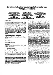
Figure 1 shows the schematic symbol of a DD-DXCCII with buffered output. The CMOS implementation of DD-DXCCII with buffered output at 𝑍𝑛 is shown in Figure 2. The input side has three terminals (called 𝑌1 , 𝑌2 , and 𝑌3 ) and there are two 𝑋-terminals (𝑋𝑝 and 𝑋𝑛 ). At the output side, there are three terminals 𝑍𝑝 , 𝑍𝑛 , and 𝑊𝑛 . For the 𝑍𝑝 terminal, the direction and magnitude of the conveyed
Zn
Izn
Wn
Vwn
Ixn Vxp
The differential difference dual-X current conveyor with buffered output has been proposed as an eight-terminal device characterized by the following port relations:
Izp
Xn
Ixp
2. Proposed First-Order All-Pass Filter
Zp
Vxn
Figure 1: Schematic symbol of DD-DXCCII.
current are the same as those of the current flowing in the 𝑋𝑝 terminal whereas for the 𝑍𝑛 terminal, the current is the same as in the 𝑋𝑛 -terminal. The voltage that appears at terminal 𝑊𝑛 is equal to the voltage at 𝑍𝑛 . The proposed tunable voltage-mode first-order all-pass filter section is shown in Figure 3. As can be seen, the circuit has minimal complexity and employs a single DD-DXCCII, a single capacitor, and an NMOS transistor biased in the triode region. The transfer function of an all-pass filter can be given as 𝑇AP =
𝑉out 𝑠 − 2/𝑅𝑀𝐶 = , 𝑉in 𝑠 + 2/𝑅𝑀𝐶
(2)
where 𝑅𝑀 is the resistance of the MOSFET transistor (𝑀) in Figure 3 and is given by 𝑅𝑀 = [𝜇𝑛 𝐶𝑜𝑥 (
−1 𝑊 ) (𝑉𝐶 − 𝑉𝑇 )] , 𝐿
(3)
The Scientific World Journal
3 VDD
M25
V𝐵1
M26
M27
M21
M22
Y1
M23
M16
M15
X𝑝
C𝑐
M28
M1
M18
M2
M3
M7
M35
M33 M36
Z𝑛 M37
C𝑐
M13
M30
M31
X𝑛
M8
M12
M11 M29
M34
M20
Z𝑝
M24
Y3
V𝐵2
M17
M19
M5
M4
M6
M9
W𝑛 M14 M32
M10
M38 VSS
Figure 2: CMOS implementation of DD-DXCCII.
Vin
Zp
Y1 C
DD-DXCCII
Zn
𝑉𝑥𝑝 = 𝛽𝑝1 𝑉𝑦1 − 𝛽𝑝2 𝑉𝑦2 + 𝛽𝑝3 𝑉𝑦3 ,
Xn
Xp
Y3
taken into consideration. The nonideal port relationship can be expressed as
Vout
Wn
𝑉𝑥𝑛 = 𝛽𝑛1 𝑉𝑦1 − 𝛽𝑛2 𝑉𝑦2 + 𝛽𝑛3 𝑉𝑦3 ,
Vc
𝐼𝑧𝑝 = 𝛼𝑝 𝐼𝑥𝑝 ,
M ID
where 𝜇𝑛 , 𝐶𝑜𝑥 , 𝑉𝑇 , 𝑊, and 𝐿 are the surface mobility, oxide capacitance, threshold voltage, channel width, and length of MOS. From (2) the pole frequency 𝜔0 can be expressed as 𝜔0 =
𝑅𝑀𝐶
.
(6)
𝑉𝑤𝑛 = 𝛾𝑛 𝑉𝑧𝑛 ,
Figure 3: Proposed tunable first-order all-pass filter.
2
𝐼𝑧𝑛 = 𝛼𝑛 𝐼𝑥𝑛 ,
(4)
where 𝛽𝑝𝑖 (𝛽𝑛𝑖 ) is the voltage transfer gain from the 𝑌𝑖 port to 𝑋𝑝 (𝑋𝑛 ) port, where 𝑖 = 1 to 3, 𝛼𝑝 (𝛼𝑛 ) is the current transfer gain from the 𝑋𝑝 port to 𝑍𝑝 port (𝑋𝑛 port to 𝑍𝑛 port) and 𝛾𝑛 is the voltage transfer gain from 𝑍𝑛 port to 𝑊𝑛 port (ideally, these transfer gains are unity in magnitude). Using (6) the ideal transfer functions of the AP filter section, given in (2), yield the following nonideal transfer function: 𝑇AP, nonideal =
𝑉out 𝑠 − (2𝛼𝑝 𝛽1 /𝑅𝑀𝐶) . = 𝑉in 𝑠 + (2𝛼𝑝 𝛽3 /𝑅𝑀𝐶)
(7)
From (7) the nonideal pole frequency can be expressed as From (4) it is clear that the pole frequency of the all-pass filter can be tuned by varying the resistance (𝑅𝑀) of the triode MOS resistor (𝑀). The phase angle of the all-pass filter can be expressed as ∠𝜙 = 𝜋 − 2tan−1 (
𝜔𝐶𝑅𝑀 ). 2
(5)
3. Nonideal Study 3.1. Effect of Nonideal Transfer Gain. The port relations defining the DD-DXCCII, as given in (1), correspond to an ideal device in which the current and voltage conveying processes are deemed perfect. For a more realistic understanding of the operation of the circuit of Figure 3, the nonidealities associated with the DD-DXCCII need to be
𝜔0, nonideal =
2𝛼𝑝 𝛽3 𝑅𝑀𝐶
.
(8)
Equation (8) shows that, due to nonideal voltage and current transfer gain, the pole frequency does get affected. The sensitivity analysis shows that the pole frequency due to the nonidealities is unity in magnitude. 3.2. Effect of Parasitics. The parasitics associated with the actual DD-DXCCII are the same as those of the DXCCII [23]. In Figure 3, 𝑌1 and 𝑍𝑝 port parasitics are in parallel; that is, 𝑅𝑦1 //𝑅𝑧𝑝 //𝐶𝑦1 //𝐶𝑧𝑝 , 𝑌3 , and 𝑍𝑛 port resistances and capacitances are also in parallel, that is, 𝑅𝑦3 //𝑅𝑧𝑛 //𝐶𝑦3 //𝐶𝑧𝑛 . Also, the 𝑋𝑝 and 𝑋𝑛 parasitics, that is, 𝑅𝑥𝑝 and 𝑅𝑥𝑛 , merge with the resistance of triode MOSFET. The proposed circuit is reanalyzed by taking into account the above parasitics
4
The Scientific World Journal
Vin
C1
Zp Wn DD-DXCCII Xn Y1 1 Zn Y3 Xp
Vc ID
M1
Zp Wn DD-DXCCII Xn Y1 2 Zn Y3 Xp
C2
Vout (n)
Zp
Vc ID
M2
Wn DD-DXCCII Xn Y1 n Zn Y3 Xp
Cn
Vc ID
Mn
Figure 4: Proposed tunable 𝑛th order all-pass filter.
1 20 2 180 d
𝑉out 𝐶+𝐶 =( )( 𝑉in 𝐶
𝑇AP,parasitic =
𝑠 − 2/𝑅𝑀 (𝐶 + 𝐶 ) 𝑠 + 2/𝑅𝑀𝐶
),
Gain (dB)
10
0
(9)
−10
where 𝐶 = 𝐶𝑦1 //𝐶𝑧𝑝 and since 𝐶 ≫ 𝐶 , the transfer function reduces to
−20
𝑇AP,parasitic
𝑉 𝑠 − 2/𝑅𝑀𝐶 = out = ( ). 𝑉in 𝑠 + 2/𝑅𝑀𝐶
(10)
From (10) it is clear that the pole frequency is unaffected in the presence of parasitics.
4. Higher Order All-Pass Filter
𝑉out 𝑉in
=(
𝑠 − 2/𝑅𝑀1 𝐶1 ) 𝑠 + 2/𝑅𝑀1 𝐶1
×(
(11)
𝑠 − 2/𝑅𝑀𝑛 𝐶𝑛 𝑠 − 2/𝑅𝑀2 𝐶2 )⋅⋅⋅( ). 𝑠 + 2/𝑅𝑀2 𝐶2 𝑠 + 2/𝑅𝑀𝑛 𝐶𝑛
From (11) the pole frequency can be expressed as 𝜔0, 𝑛th order =(
2𝑛 ) (𝑅𝑀1 ⋅ 𝑅𝑀2 ⋅ ⋅ ⋅ 𝑅𝑀𝑛 ) ⋅ (𝐶𝑀1 ⋅ 𝐶𝑀2 ⋅ ⋅ ⋅ 𝐶𝑀𝑛 )
90 d
0d 10 kHz
100 kHz
1.0 MHz
f0 (MHz) = 4 f0 (MHz) = 5 f0 (MHz) = 6
10 MHz
100 MHz
Frequency
Figure 5: Frequency response showing gain and phase of APS of Figure 3.
5. Design and Verification
It is well known that higher order filters exhibit a larger rate of phase change at constant magnitude when compared to a first-order filter. They can also be used as a group delay equalizer in video and communication applications. These features are the motivating factor behind realizing a higher order filter in this work. The proposed 𝑛th order APF filter is presented in Figure 4 which is obtained by cascading 𝑛-stages of the first-order filter described in Figure 3. The proposed filter employs 𝑛-stages of DD-DXCCII and 𝑛-capacitors and MOS resistors operating in the triode region. Analysis of the above circuit yields the following transfer function: 𝑇AP, 𝑛th order =
Phase (deg)
(assuming 𝑅𝑀 ≫ (𝑅𝑥𝑝 + 𝑅𝑥𝑛 )). The nonideal transfer gain due to parasitics then becomes
1/𝑛
. (12)
The performance of the first-order all-pass shown in Figure 3 was verified using PSPICE program. Supply voltages were kept at ±1.25 V. The proposed filter was designed with 𝐶 = 10 pF and gate control voltages are 𝑉𝐶 = 0.8 V, 1.0 V, and 1.2 V. The gain and phase plot is shown in Figure 5 which shows the variation in pole frequency at different control words. As can be seen, the pole frequency is varied from 4 MHz, 5 MHz, and 6 MHz at 𝑉𝐶 = 0.8 V, 1.0 V, and 1.2 V, respectively. The time domain response of the proposed allpass filter as shown in Figure 6 is obtained by applying a sine wave of 80 mV peak-to-peak amplitude at 6 MHz. The output is 88.9∘ phases shifted, which corresponds well with the theoretical value of 90∘ . The total harmonics distortion was found to be 1% at pole frequency of 6 MHz. The Fourier spectrum of input and output waveform is also shown in Figure 7. The circuit proposed in Figure 4 is verified for a thirdorder filter; that is, 𝑛 = 3. The filter was designed at 𝐶 = 10 pF at different gate control voltages of the MOS transistor; that is, 𝑉𝐶 = 0.8 V, 1.0 V, and 1.2 V. Simulated gain and phase response at different pole frequencies is shown in Figure 8. The pole frequencies are found to be 4 MHz, 5 MHz, and 6 MHz at a phase of −90∘ . The variation in pole frequency is obtained by varying the control word. The total harmonics distortion (THD) variation of first- and third-order filter is shown in Figure 9, which shows that the THD variation is around 3% up to 300 mV of the variation in the input signal amplitude.
The Scientific World Journal
5 8
100 mV
7 Vout
Amplitude
3rd order 1st order
6 THD (%)
Vin
0V
5 4 3 2 1 0
0
100
200
300
400
Input voltage (peak-to-peak (mV)) −100 mV
Figure 9: THD variation of 1st and 3rd order filter. 200 ns
0s
400 ns
600 ns
Time
6. Conclusion
V(5) V(1)
In this paper a new active element, that is, DD-DXCCII with buffered output, is presented. By employing DD-DXCCII a new voltage mode tunable resistorless all-pass filter using single passive element is realized. The proposed filter does not require any matching condition. The filter has low output impedance which is elaborated by designing a third-order filter. Nonidealities of the active element along with parasitics are also considered, so as to evaluate the proposed filter. The filter reported in [23, 24] is a current mode all-pass filter while the filter presented in this work is a voltage mode all-pass filter.
Figure 6: Time domain response of APS at 6 MHz.
40 mV
Vin
Amplitude
Vout 20 mV
Conflict of Interests The author declares that there is no conflict of interests regarding the publication of this paper.
0V 0 Hz
20 MHz
40 MHz
60 MHz
Frequency
Acknowledgment
V(1) V(5)
Figure 7: Fourier spectrum of input and output at 6 MHz.
The author would like to thank the editors for recommending this paper.
References
10 0 −10 −20
2 180 d Phase (deg)
Gain (dB)
1 20
0d
−200 d −360 d 100 kHz
1.0 MHz 10 MHz Frequency
100 MHz
f0 (MHz) = 4 f0 (MHz) = 5 f0 (MHz) = 6
Figure 8: Frequency response showing gain and phase of 3rd order APS of Figure 4.
[1] T. Tsukutani, H. Tsunetsugu, Y. Sumi, and N. Yabuki, “Electronically tunable first-order all-pass circuit employing DVCC and OTA,” International Journal of Electronics, vol. 97, no. 3, pp. 285– 293, 2010. [2] M. A. Ibrahim, S. Minaei, and E. Yuce, “All-pass sections with rich cascadability and IC realization suitability,” International Journal of Circuit Theory and Applications, vol. 140, pp. 477–488, 2012. [3] S. Maheshwari, “A canonical voltage-controlled VM-APS with grounded capacitor,” Circuits, Systems, and Signal Processing, vol. 27, no. 1, pp. 123–132, 2008. [4] S. Minaei and O. Cicekoglu, “A Resistorless realization of the first-order all-pass filter,” International Journal of Electronics, vol. 93, no. 3, pp. 177–183, 2006. [5] S. Minaei and E. Yuce, “Novel voltage-mode all-pass filter based on using DVCCs,” Circuits, Systems, and Signal Processing, vol. 29, no. 3, pp. 391–402, 2010.
6 [6] S. Maheshwari, “High input impedance voltage-mode firstorder all-pass sections,” International Journal of Circuit Theory and Applications, vol. 36, pp. 511–522, 2008. [7] S. Maheshwari, “High input impedance VM-APSs with grounded passive elements,” IET Circuits, Devices and Systems, vol. 1, no. 1, pp. 72–78, 2007. [8] S. Maheshwari, J. Mohan, and D. S. Chauhan, “Novel voltagemode cascadable all-pass sections employing grounded passive components,” Journal of Circuits, Systems, and Computers, vol. 22, Article ID 1250065, 2013. [9] A. M. Soliman, “Generation of current conveyor-based allpass filters from op amp-based circuits,” IEEE Transactions on Circuits and Systems II: Analog and Digital Signal Processing, vol. 44, no. 4, pp. 324–330, 1997. [10] J. Mohan, S. Maheshwari, and D. S. Chauhan, “Voltage mode cascadable all-pass sections using single active element and grounded passive components,” Circuits and Systems, vol. 1, pp. 5–11, 2010. [11] K. Pal and S. Rana, “Some new first-order all-pass realizations using CCII,” Active and Passive Electronic Components, vol. 27, no. 2, pp. 91–94, 2004. [12] N. Herencsar, J. Koton, J. Jerabek, K. Vrba, and O. Cicekoglu, “Voltage-mode all-pass filters using universal voltage conveyor and MOSFET-based electronic Resistors,” Radioengineering, vol. 20, no. 1, pp. 10–18, 2011. [13] S. Maheshwari, “Voltage-mode all-pass filters including minimum component count circuits,” Active and Passive Electronic Components, vol. 2007, Article ID 79159, 5 pages, 2007. [14] M. A. Ibrahim, H. Kuntman, and O. Cicekoglu, “First-order allpass filter canonical in the number of resistors and capacitors employing a single DDCC,” Circuits, Systems, and Signal Processing, vol. 22, no. 5, pp. 525–536, 2003. [15] S. Maheshwari and B. Chaturvedi, “High-input low-output impedance all-pass filters using one active element,” IET Circuits, Devices and Systems, vol. 6, no. 2, pp. 103–110, 2012. [16] S. Maheshwari and I. A. Khan, “Novel first order all-pass sections using a single CCIII,” International Journal of Electronics, vol. 88, no. 7, pp. 773–778, 2001. [17] S. Minaei and E. Yuce, “Unity/variable-gain voltage-mode/ current-mode first-order all-pass filters using single dual-X second-generation current conveyor,” IETE Journal of Research, vol. 56, no. 6, pp. 305–312, 2010. [18] D. Biolek and V. Biolkova, “First-order voltage-mode allpass filter employing one active element and one grounded capacitor,” Analog Integrated Circuits and Signal Processing, vol. 65, no. 1, pp. 123–129, 2010. [19] M. A. Ibrahim, H. Kuntman, S. Ozcan, O. Suvak, and O. Cicekoglu, “New first-order inverting-type second-generation current conveyor-based all-pass sections including canonical forms,” Electrical Engineering, vol. 86, no. 5, pp. 299–301, 2004. [20] B. Metin and O. Cicekoglu, “Component reduced all-pass filter with a grounded capacitor and high-impedance input,” International Journal of Electronics, vol. 96, no. 5, pp. 445–455, 2009. ¨ [21] A. Toker, S. Ozcan, H. Kuntman, and O. C ¸ ic¸ekoˇglu, “Supplementary all-pass sections with reduced number of passive elements using a single current conveyor,” International Journal of Electronics, vol. 88, no. 9, pp. 969–976, 2001. [22] S. Maheshwari, J. Mohan, and D. S. Chauhan, “Voltage-mode cascadable all-pass sections with two grounded passive components and one active element,” IET Circuits, Devices and Systems, vol. 4, no. 2, pp. 113–122, 2010.
The Scientific World Journal [23] P. Beg, M. A. Siddiqi, and M. S. Ansari, “Multi output filter and four phase sinusoidal oscillator using CMOS DX-MOCCII,” International Journal of Electronics, vol. 98, no. 9, pp. 1185–1198, 2011. [24] J. Mohan and S. Maheshwari, “Cascadable Current-mode first order all-pass filter based on minimal components,” The Scientific Word Journal, vol. 2013, Article ID 859784, 5 pages, 2013.