Tutorial – Minor Losses using Pointwise and FLUENT Part 1 ...
Recommend Documents
Jan 17, 2011 ... CFD solver to calculate the pressure drop across the inlet and outlet of the ... This
tutorial assumes that SolidWorks is running. 2. File-New. 3.
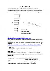
Copy the uvinlet_tut1.c from the link in a text editor, http://www.soton.ac.uk/~zxie/SESS6021/Airfoil/UDF/uvinlet_tut1.c and save it in the folder where the Fluent ...
1. Fluent UDF tutorial. An airfoil in a free shear layer (a wake, or due to the
stratification of the atmosphere). Design the inlet conditions for this case. Then
apply ...
(the question mark in the Geometry cell is replaced by a check mark, indicating that there is a ..... flowing into the computational domain through the outlet.
Introduction to Using ANSYS FLUENT in. ANSYS Workbench: Fluid Flow and
Heat Transfer in a. Mixing Elbow. Introduction. This tutorial illustrates using
ANSYS ...
so each step will be explicitly described. ... ANSYS, Inc. March 12, 2009 ... Setup
and Solution. Preparation. 1. Download introduction.zip from the User Services ...
Sep 21, 2006 - Airpak, FIDAP, FLUENT, FLUENT for CATIA V5, FloWizard, GAMBIT, ...... first-order discretization is the default scheme in FLUENT, it is good practice to use ...... which is a ceramic structure coated with a metal catalyst such as .....
Airpak, FIDAP, FLUENT, GAMBIT, Icepak, MixSim, and POLYFLOW are
registered trademarks of Fluent ... 21 Using the Eulerian Granular Multiphase
Model with Heat Transfer. 22 Postprocessing ... all contain some postprocessing
as well).
Select polynomial from the Density drop-down list to open the Polynomial Profile ... Select liquid-metal from the FLUENT Fluid Materials drop-down list to set the ...
enabled (or vice versa), click the check box or the text. iii. Make sure that the Double Precision option is disabled. b. Click OK to launch ANSYS FLUENT. 27.
Chapter 3: Introduction to Using ANSYS FLUENT: Fluid Flow and ... Click the ANSYS Fluid Dynamics Tutorial Inputs link to download the ANSYS_Fluid_Dynam-.
b. Select water-liquid from the Phase Material drop-down list. c. Click OK to close the Primary Phase dialog box. 2. Specify air as the secondary phase. Phases ¡.
Select ideal-gas from the Density drop-down list, so that the ideal gas law is used to calculate density. Note. ANSYS FLUENT automatically enables the solution ...
Page 1. Fleur Kusudama. N'ayant pas le tutoriel en français, voici les photos pas
à pas pour réaliser une fleur Kusudama…
of the conversion. .... It is a good idea to check the mesh after you manipulate it (i.e., scale, convert to poly- ...... H. Enable Wireframe in the Refine group box.
MINOR BUDDHIST TEXTS. P A R T I. Asanga's commentary on the
Vajracchedikd edited and translated -. Analysis of the commentary on it by
Vasubandhu ...
Database Tutorial. Page 1 of 10. VBScript Database Tutorial Part 1. Probably the
most popular use for ASP scripting is connections to databases. It's incredibly ...
The PICAXE VSM Tutorial is split into a number of chapters. Each chapter ...
Overview. Figure 1 - Circuit simulation of the AXE107 Rudolph Project Kit (www.
rev-.
Jan 17, 2011 ... Pointwise to OpenFOAM Tutorial – Laminar Flow through a Straight Pipe ... This
tutorial provides instructions for meshing an internal flow in a.
Hence CFD analysis is used to design. efficient catalytic converters: by modeling the exhaust gas flow, the pressure dro
On this site, where each banner is, a PHP script is called. This opens a ...... If you
remember back to creating the database for the contacts at the beginning of this.
Oct 17, 2009 ... XAMPP is a free download and is available for various platforms. .... We will also
configure PHP so that it integrates with Eclipse - our IDE ( ...
John Day, 2010. All Rights Reserved. The Myths and “Principles” are the Major.
Barrier to FINDing an Answer. • The Answer has been clear since the mid-90s.
This tutorial covers the usage of a very powerful open source intelligence (OSINT
) tool .... BackTrack 5 tutorial Part I: Information gathering and VA tools.
Tutorial – Minor Losses using Pointwise and FLUENT Part 1 ...
17 Jan 2011 ... This tutorial provides instructions for meshing two internal flows. Pointwise
software will be used to create the meshes, and FLUENT will be ...
Workbench Tutorial – Minor Losses, Page 1
Tutorial – Minor Losses using Pointwise and FLUENT Authors: Scott Richards, Keith Martin, and John M. Cimbala, Penn State University Latest revision: 17 January 2011
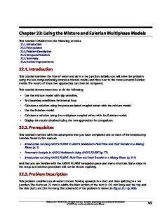
Introduction This tutorial provides instructions for meshing two internal flows. Pointwise software will be used to create the meshes, and FLUENT will be used as the CFD solver. The first flow is in a straight pipe, and the second flow is in a pipe of the same length and diameter, but with a 90° elbow. The pressure drop is calculated for both cases. The difference in pressure drop between the two cases is due solely to the elbow since the pipes are the same length; this is the so-called “minor loss”. In Part 1 of this tutorial, a geometry and mesh like the one shown to the right will be created. This tutorial shows how to use “extrusion” to generate a fine grid near a wall and a structured mesh everywhere else.
Part 1: Straight Pipe Choose solver 1. This tutorial assumes that Pointwise is running. If it is not running, open it before proceeding to the next step. 2. It is wise to choose the desired CFD solver before creating any grids. Setting the solver first reduces the possibility of problems later when exporting the mesh. 3. CAE-Select Solver… 4. ANSYS FLUENT. 5. OK. The current solver is displayed in the lower left of the Pointwise window. 6. File-Save. 7. After selecting an appropriate folder in which to save the project, enter “Straight_Pipe_MinorLoss” for the File Name. Save.
Create geometry in Pointwise 1. Because of symmetry, it is not necessary to model the entire pipe. Only one-quarter of the pipe will be analyzed; this change in geometry reduces the analysis time by approximately 75%. 2. View-Toolbars and verify that all toolbars are activated (a check by each title). 3. Defaults tab. Make sure the box to the left of Connector is checked. 4. Enter “21” in as the default dimension. List tab. The default dimension is the number of nodes assigned to each connector created after setting the default. 5.
2 Point Curves from the Create toolbar. Hover the cursor over any toolbar button to display its name. Alternatively, Create-2 Point Curves... 6. Under Point Placement, type “0 0.02625 0” as the XYZ coordinates for the first endpoint. . Use the following format entering Point Placement data: “x-coordinate” “ycoordinate” “z-coordinate”. 7. Type “0 0 0” as the XYZ coordinates for the second endpoint. .
Workbench Tutorial – Minor Losses, Page 2
Delete Last Point if a wrong coordinate is entered. 8. again to place another point at “0 0 0”. 9. Type “0.02625 0 0”. . 10. Type “0 0.02625 0.68247”. . 11. Type “0 0 0.68247”. . 12. again to place another point at “0 0 0.68247”. 13. Type “0.02625 0 0.68247”. . 14. OK. 15. Rotate the axis to an isometric view by holding down and the RMB while moving the cursor to the left. 16. View-Zoom-Zoom to Fit. Alternatively, press on the keyboard. 2 Point Curves. 17. 18. LMB Point1, then LMB Point2 to create a long connector. 19. LMB Point3, then LMB Point4 to create a second long connector. 20. LMB Point5, then LMB Point6 to create a third long connector 21. OK. 22.
Curve from the Create toolbar. Alternatively, Create-Draw Curves-Curve. 23. Circle. LMB “2 Points & Center” under Circle Segment Options. 24. LMB Point1, then LMB Point5. LMB Point3 to place the center of the circle. Apply. 25. LMB Point2, then LMB Point6. LMB Point4 to place the center of the circle. Apply. 26. OK. 27. LMB the “+” next to Connectors in the List side panel. The expanded list shows the type and number of nodes assigned to every connector. A “connector” is the Pointwise terminology for a construction line.
Modify axial dimension 1. Simultaneously select the four longest connectors (“con-5”, “con-6”, and “con-7”). Hold while LMB to make multiple selections. Selections can be made in the graphics window or from the List side panel. 2. Grid-Dimension… 3. Type “100” for Number of Points. Dimension-OK. These points will space the mesh cells in the axial direction. Sometimes it is helpful to make the spacing nodes visible. To do this, select all the connectors by + . Choose “Points On” from the drop down menu beside “ Points Off” in the attributes toolbar.