where {a,} is the code sequence, which is the output of the line coder. The parameter C is defined as C = max, Is, 1. Pierobod proved that the spectrum of the ...
TWO NEW TERNARY LINE CODES
contents of the sliding block decoder are shown, together with the data represented. Decoding should take place after every second symbol is shifted into the buffer. Table 4 shows the decoder for the 2B2TA line code.
Indexing terms: Ternary line codes, Code synthesis
Two new ternary line codes are presented. Although the two codes are similar, they differ with respect to error propagation properties and power spectral densities. The codes are relatively simple, yet they satisfy tight channel input restnctions, making them suitable for use in practical baseband communications systems. A line code that is suitable for use in baseband communications systems generally satisfies one or both of the following channel input restrictions:’J (i) The code sequence should contain no zero-frequency components, and should have small low-frequency components. The running digital sum (RDS) of a code sequence of length I is defined as s, =
Table 2 ENCODER FOR 2B2TA LINE CODE
State A Data
Code
00
+ -
01
10
f O
ti
I
(ii) When using NRZ pulses, the code sequence should have frequent transitions between symbols to enable the encoder clock signal to be derived from the code sequence at other equipment. The parameter L””’ denotes the maximum runlength of any symbol. A line coding scheme with a mapping ratio of R = mjn maps every group of m data bits onto n code symbols. The channel capacity, H, of a discrete input restricted channel is the highest possible value of R that can be achieved by any coding scheme which satisfies the channel input restrictions4 The sequence utilisation efficiency of a line code is defined as 7 = R / H x 100%.‘ Ferreira et al.’ presented the Markov models and values of H for ternary sequences conforming to different classes of channel input restrictions. The channel capacity of a ternary sequence consisting of symbols ‘+’, ‘-’, and ‘ 0 with C = 1 and I!!’ = 2 is H = 1.2001 bits/symbol. A line coding scheme which generates the above mentioned ternary sequence with a mapping ratio of R = 1, would then have a sequence utilisation efficiency of q = 83%. The sequence state coding methods of Franaszek’ were applied to the Markov model of the above mentioned ternary sequence. A graph consisting of three states was found, each with four outgoing edges. Each edge is associated with two output symbols, making the construction of a coding scheme for mapping every two data bits onto two code symbols possible. Groups of two data bits were successfully assigned to groups of two code symbols in such a way that a sliding block decoder consisting of a serial buffer of length two symbols could be found, limiting the number of data errors caused by a single, isolated channel error to at most two data bits. A second code was found with an alternative mapping of data bits onto code symbols. The codes were named 2B2T and 2B2TA, respectively. The Mealy-machine representation of the encoder for the 2B2T line code is shown in Table 1, and the encoder for the 2B2TA code in Table 2. Table 3 is the decoder table for the 2B2T code. In this Table, all the possible buffer Table 1 ENCODER FOR 2B2T LINE CODE
State A Data
Code
00
+ -
01
O
10 11
f
+ + +
O
State B
Next state A B
Code
+ O
f
c
-
f
B
0
-
ELECTRONICS LETTERS
State C
Next state B C B A
Code -
0
Next state
0
A B
-
B
-
+
22nd November 1990
c
Vol. 26
I
Code
+ -
A B B c
Buffer contents
Data
+~--
0 0
+ +
I O
k= 1
where { a , } is the code sequence, which is the output of the line coder. The parameter C is defined as C = max, Is, 1 . Pierobod proved that the spectrum of the sequence { a k }vanishes at zero frequency if and only if the RDS, or C, is limited.
O f
State C
Next state
-
-
+
B A C
0 -
0
I
R
-
0
-
O -
Next state
Code
A B B
c
I
Table 3 DECODER FOR 2B2T LINE CODE
(1)
ak
State B
Next state
Buffer contents O
f
-
Data 0 1
0
+ o
-
0
1 1
-
Table 4 DECODER FOR 2B2TA LINE CODE
Buffer contents
Data
+ - -
0 0
+ 0
-
I
+ +
O
0 f
Buffer contents
O
O -
Data 0
1
1 1
-
In order to determine the error propagation properties of the new codes and other ternary line codes, the discrete ternary communications channel was assumed to be subjected to additive Gaussian noise, for example near-end crosstalk (NEXT).6 The channel was assumed to have a high signal-tonoise ratio, so that the probability for a ‘+’ to be received as a ‘-’ and vice versa are negligible. We used this channel model and simulations on a digital computer to obtain the error propagation properties of the new codes as well as that of a few filled bipolar ternary line codes’ for purposes of comparison. When decoding the latter codes, the zero substitution sequence was detected in different ways for the HDBn and BnZS codes.’ The sequence that was detected is indicated in brackets where the results are presented. A ‘ B denotes a pulse that adheres to the bipolar rule. A ‘ X represents any ternary symbol. ‘B/0 denotes either a pulse obeying the bipolar rule or a ternary zero, and a ‘V’ represents a pulse that violates the bipolar rule.’ Table 5 shows the probability for each number of errors to occur at the decoder output because of a single, isolated channel error for several commonly-used ternary line codes.’.’ It is clear from Table 5 that 2B2TA has preferential error propagation properties than 2B2T. Table 5 ROUNDED SINGLE CHANNEL ERROR
PROBABILITY Number of errors Line code
0
1
2
3
4
HDBZ(B/OOV) HDB2(XX V) HDB3(B/OOOV) HDB3(X X X V ) B4ZS(VBVB) B4ZS(VXV X) B6ZS(OVBOVB) B6ZS(X V X X VX) PST 2B2T 2B2TA
0.04
0.38 0.29
0.41
0.06 0.02 0.03 0.00 0.02 0.00 0.01 0.00 0.22 0.00
0.18 0.14 0.17 0.27
0.00 0.00
No. 24
0.54
0.19 0.82 0.82 0.94
0.94 1.00 0.78 1.00
0.51 0.27 0.45
0.00 0.01
0.15
0.12 0.00 0.04 0.00 0.03 0.00 0.00 0.00 0.00 0.00 0.00
5
0.00 0.00 0.00 0.00
0.06 0.00 0.00 0.00 0.00 0.00 0.00 040
000 003 0.03 002 0.02 0.00
0.00 000 1989
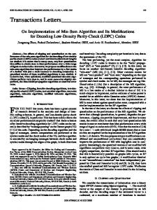
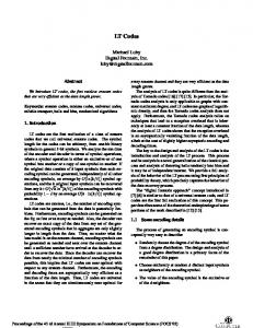
The power spectral densities (PSD) of the new codes were calculated using the methods of Cariolaro et al.’ Figs. 1 and 2
important than slightly more favourable error propagation properties. 2B2TA would be preferred where favourable error propagation is more important than the suppression of line components. L. BOTHA H. C. FERREIRA
14th September 1990
Laboratory for Cybernetics Rand Afrikaans University PO Box 524, Johannesburg 2000, South Africa
M. WHALLEY Department ofElectrica1 Engineering University ofthe Witwatersrand PO Wits, 2050, South Africa
References normalised frequency
and NEL, A. L.: ’On ternary error correcting line codes’, IEEE Trans., 1989, COM-37, (5), pp. 51&515 DUC, N. Q.: ‘Line coding techniques for baseband digital transmission’, Australian Telecomm. Res., 1975,9, (I), pp. 3-17 PIEROBON, G. L.: ‘Codes for zero spectral density at zero frequency’, IEEE Trans., 1984, IT-30, pp. 435-439 SHANNON, r. E.: ‘A mathematical theory of communication’, Bell Syst. Tech. J . , 1948, 27, pp. 379423 FRANASZEK, P. A . : ‘Sequence state coding for digital transmission’, Bell Syst. Tech. J . , 1968, 47, pp. 14G157 NARAYANA, M. B. R.: ‘Crosstalk loss requirements for PCM transmission’, IEEE Trans., 1976, COM-24, pp. 88-97 SIPRFS, J . M . : ‘A new class of selected ternary pulse transmission plans for digital transmission lines’, IEEE Trans., 1965, COM-13, (3), pp. 366372 CARIOLARO, G . L., PIEROBON, G . L., and TRONCA, G . P.: ‘Analysis of codes and spectra calculations’, Int. J . Electron., 1983, 55, (l), pp.
FERREIRA, H . c.. HOPE, J. F.,
EEC
Fig. 1 Continuous PSD for sequences by 2B2T code U p=0.3 p=o5 0 p=0.7
+
35-79
norrnallsed frequency
Izos,z:
’SYNC H RON0US‘ C D MA DEM0NSTRATIO N FOR FIBRE-OPTIC NETWORKS WITH OPTICAL PROCESSING
Fig. 2 Continuous PSD for sequences by 2B2TA code 0 p=0.3 + p=0.5 0 p = 0.7
show the continuous parts of the spectra of 2B2T and 2B2TA, respectively, for different values of p . the probability for a 1 to occur in the input data. The frequency scales are normalised with respect to l / K , where T, is the output symbol period. In both cases, only one half of the symmetric spectrum is shown. Table 6 shows the discrete parts (line components) of the spectra of 2B2T and 2B2TA. It is clear that 2B2T have negligible line components, whereas 2B2TA starts to exhibit line components when p # 0. Table 7 lists several commonly used line codes together with their input restrictions and mapping ratios. It can be seen that 2B2T and 2B2TA satisfy the tightest input restrictions of all the lines codes listed. The code 2B2T would be preferred where the suppression of line components in the PSD is more Table 6 DISCRETE PSD O F 2B2TA AND 2B2T Freouencv
2B2TA ZB2T
O.Oo0
OOOO
O.Oo0
O.Oo0
O.Oo0 0.001
0.128
O.Oo0
0.033
O.Oo0
0.128 0.005
Table 7 COMPARING TERNARY LINE CODES
R
Code
C
L”””
R
2 2 2
1
1,333
3 2 1 1
1.333
6
MS43 PST 2B2T 2B2TA
5
5
1 1 1
Code
C
L!’
AMI HDB3 B6ZS 4B3T
1 2 2
m
4
1990
3
1 1
Indexing terms: Fibre optics, Communication networks
‘Synchronous’ code-division multiple-access (S/CDMA) for fibre-opticnetworks with optical processing is investigated. A two-user experiment demonstrating the feasibility of such a network is performed at 10 Mbit/s (500 Mchip/s) using modifiedpnme sequence codes and optical processing. Fibre-optic delay-lines are used for code sequence generation and correlation without using fast electronic components. An environment in which SjCDMA would be particularly suitable is discussed. Introduction: ‘Synchronous’ code-division multiple-access for (S/CDMA) fibre-optic networks with optical processing is investigated’,’ and compared with code-division multiple access (CDMA).3 Contrary to CDMA, SjCDMA requires that network access among all users be synchronised. In general, because of the randomness in network access due to the nonscheduled transmissions, CDMA can allow only a limited number of subscribers and even fewer simultaneous users. SjCDMA with rigorous transmission schedules is shown to produce higher throughput and accommodate more subscribers than CDMA.’ Fixed assignment time-division multiple-access (TDMA); the optimal synchronous access scheme for a fibre-optic network, is a special and limiting case of S/CDMA. Contrary to S/CDMA, TDMA is better suited for services with high trafic density or that require high bit rate transmission. As indicated later, by combining both TDMA and S/CDMA on the same network, services with different trafic requirements and signalling rates can be integrated with a single clock.5 System description: In a CDMA system, each data bit 1 is encoded into a waveform s(n), consisting of a code sequence of
ELECTRONICS LETTERS
22nd November 1990 Vol. 26 No. 24 -
.