Abstract. A two-step parameter-free approach for non-rigid medical image registration is presented. Displacements of boundary structures are computed in the ...
Two-Step Parameter-Free Elastic Image Registration with Prescribed Point Displacements Wladimir Peckar
Christoph Schnorr H. Siegfried Stiehl
Karl Rohr
Universitat Hamburg, FB Informatik, AB Kognitive Systeme, Vogt-Kolln-Str. 30, D-22527 Hamburg, Germany Abstract
A two-step parameter-free approach for non-rigid medical image registration is presented. Displacements of boundary structures are computed in the rst step and then incorporated as hard constraints for elastic image deformation in the second step. In comparison to traditional non-parametric methods, no driving forces have to be computed from image data. The approach guarantees the exact correspondence of certain structures in the images and does not depend on parameters of the deformation model such as elastic constants. Numerical examples with synthetic and real images are presented.
1 Introduction Numerous applications in modern medical imaging deal with non-rigid image registration. Examples are image-atlas as well as multi-modality image registration in neurosurgery. There, a three-dimensional image (deformable template ) has to be completely transformed onto another one (study ). One group of methods dealing with non-rigid image registration is the so-called non-parametric methods, where the degrees of freedom of admissible deformations are not de ned by a xed number of parameters [1], [3]. The non-parametric methods model the non-rigid transformations as deformations of physical bodies (solids, liquids) caused by applied forces. The traditional image registration scheme using non-parametric methods is the 1
following: Applied forces are rst derived from image data using some similarity measure and then used to deform the template image driving it to a correspondence with the study image. In this paper, we propose a two-step registration approach based on elasticity theory. In the rst step, we determine point correspondences of some boundary structures in both images by using an active contour model also known as snake model. In the second step, we elastically deform the template image by using the prescribed values of displacements of boundary structures obtained in the rst step incorporated as hard constraints in addition to the conditions on the image boundary. This approach has several advantages compared to traditional methods. i) No driving forces have to be derived from image data. For multi-modality images using a local similarity measure, this is known to be a di�cult problem. ii) As a consequence, the remaining parameters of the deformation model (elastic constants) drop out from the model and it becomes completely parameter-free. iii) It can always be guaranteed that the required deformation is obtained and that certain structures in the template are exactly matched with those of the study.
Relationship to Other Work
Application of non-parameteric methods to medical image registration originated from the work of Broit [2], where images were represented as pieces of rubber and the cross-correlation coe�cient between two images was used for the derivation of forces. This linear elastic model has been improved to increase the speed of computations and to avoid local minima [1], [15]. Two main drawbacks of this model are the assumption of small displacements and the usage of a local similarity measure. Gee et al. [11] proposed a probabilistic approach based on the nite element method which has been reported to have properties similar to those of [2], [1]. Another group of non-parametric methods which is based on the principles of uid mechanics has been introduced by Christensen et al. [3], [4]. These methods use properties of uids that do not carry memory about their initial state, thus allowing large deformations. However, a local similarity measure is still used, which considerably limits the applicability of the uid model as a general model for registration problems. The present paper describes a further development of the approach introduced in [14] and is closely related to the work of Davatzikos et al. [10], [9], where no local similarity measure is used and external forces are de ned on the basis of correspondence of boundary structures such as the outer cortical boundary and the ventricles. The principal di�erence to our approach is, however, that we do not use any external forces. As a consequence, parame2
ters of the deformation model, such as elastic constants, are not required for our approach. Incorporation of known displacements as hard constraints in the model allows the exact matching of the boundary structures. In the following, we describe the two steps of our registration approach, its discrete representation, and present some numerical examples with synthetic and real images.
2 Two-Step Registration Model In this section, we present the two steps of our registration approach. The snake model in the rst step was used for demonstration purposes in order to de ne simple point correspondences between boundary structures in two dimensions. It will be replaced in the future by more e�cient methods. The elastic model is presented for the three-dimensional case.
2.1 First Step: Snake Model
Snakes were rst proposed by Kass et al. [13] as a general energy minimizing model which can be applied to numerous problems in computer vision (edge detection, tracking of moving objects, etc.). Since the time of introduction of snakes, several improvements have been made in the model (see, for example, [8], [7]). In this paper, we use the original model from [13]. Snakes are parametrically de ned curves v(s) = (x(s); y(s)). The snake model minimizes the following energy: E
Z = f�(s)kv (s)k + (s)kv (s)k + P (v(s))g ds 0
snake
2
00
2
(1)
consisting of the internal energy of the curve and the potential P corresponding to the external forces derived from image data. Two parameters � and control elastic properties of the snake. Since we are interested in nding edges, we use the following potential: P (v(s)) = ,jrI (v(s))j;
(2)
where I (v(s)) denotes the image function. The result is a curve converging to the boundary of the object when placed close enough to it.
2.2 Second Step: Linear Elastic Model
Here, we present outlines of the variational formulation of the threedimensional linearized elasticity problem. 3
Let be an open, bounded, connected subset of R 3 with a Lipschitzcontinuous boundary , (, = ,0 [ ,1; ,0 \ ,1 = ;). We de ne a normed vector space
V := fv = (v1; v2; v3) 2 (H 1( ))3; v = 0 on ,0 � ,; i = 1; 2; 3g: t
i
The variational problem of the linearized elasticity which couples displacements in elastic materials with applied body and surface forces can be formulated as [5]: Find u 2 V such that a(u; v) = f (v);
8v 2 V;
(3)
where the symmetric bilinear form a(u; v) and the linear form f (v) are de ned as
Z X e (u)e (v)g dx; a(u; v) = f�(r � u)(r � v) + 2� Z Z f (v) = f � v dx + g � v d : 3
ij
i;j
ij
=1
,1
(4) (5)
Here, f = (f1 ; f2; f3) 2 (L2 ( ))3 and g = (g1; g2; g3) 2 (L2 (,1))3 denote applied body and surface forces respectively, 1 e (v) = e (v) = (@ v + @ v ); i; j = 1; 2; 3 (6) 2 is the linearized strain tensor, u; v 2 V denote the displacement eld, � and � are Lam�e elastic constants. In the following, we use a simpli ed model by supposing , = ,0 , and setting the parameter � to zero. The last choice is quite common for nonrigid registration problems, because in that case objects in images are allowed to grow without being laterally shrunk [1], [4]. The elastic model is now: Find u 2 V such that t
ij
t
ji
j
i
a(u; v) = f (v);
where
i
j
8v 2 V;
Z a(u; v) = 2� (e(u); e(v)) dx; Z f (v) = f � v dx:
Here (� ; �) denotes the usual matrix inner product. 4
(7) (8) (9)
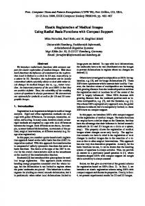
Figure 1: Deformation with prescribed point displacements of a 3D synthetic image. Top/left: Prescribed displacements. Top/right: Computed 3D displacement eld. Bottom: Horizontal layers 3, 4, 5 from the 3D computed displacement eld above. From (8)-(9), one can see that the parameter � can now be considered as a scaling coe�cient for the applied forces. Since we use prescribed displacements instead of applied forces, the elastic model becomes completely parameter-free. It can be shown that the problem (7) has a unique solution (see [14], [6] for details). In the next section, we will discuss the nite element discretization of the problem (7).
2.3 Discrete Representation
Following [13], we solved Euler equations corresponding to the snake model (1) iteratively by approximating the derivatives with nite di�erences and using constant parameters � and . For the discretization of the elasticity problem (7), we used the Galerkin method [5]: By replacing the space V with a nite-dimensional subspace 5
Figure 2: Two-step deformation with prescribed displacements. Left: Two corresponding boundary structures. Middle: Deformation of a synthetic image. Right: The same deformation applied to a rectangular grid.
V := spanf�1; : : : ; � g, we seek a discrete solution to the problem: Find u 2 V such that a(u ; v ) = f (v ); 8v 2 V : (10) The solution vector u = fu g is obtained as a solution of the system of N
N
N
N
N
N
N
linear equations:
N
N
N
i
X u Z f X e (� )e (� )g dx = 1 Z f � � dx; j = 1; : : : ; N: 3
N
i
=1
i
kl
k;l
=1
i
kl
2�
j
j
(11)
j
The system (11) can be written in matrix form as
Au = b
(12)
N
with symmetric and positive de nite sti�ness matrix A.
2.4 Prescribed Displacements
To incorporate prescribed values of u , we transform the matrix A in (12) by lling its i-th row and column with 0 and setting the element A to 1. Since each row of A contains contributions of more than one nite element, i
ii
6
the transformed matrix A~ will always be invertible. Then we set the initial vector b to zero, subtract the product u A from it (A denotes here the i-th column of A), and put u in the i-th position in b~ = b , u A [16]. i
i
i
i
i
i
3 Numerical Examples In this section, some numerical examples for our two-step registration approach will be presented. The deformations for all examples were based on prescribed point displacements, while no external forces have been used. Figure 1 illustrates the usage of prescribed displacements for a 3D synthetic image which has the size of 12x12x12 voxels. At the top of the gure, the prescribed displacements (top/left) and the computed displacement eld (top/right) are shown. In the bottom of the gure, there are three 2D horizontal layers from the displacement eld above. For this example, layers 3, 4, and 5, starting from the top were chosen. This example illustrates also the usage of the homogeneous Dirichlet boundary condition (v = 0 on ,, where , is the image boundary). Figure 2 (left) presents two corresponding boundary structures, where the image below is a result of some iterations of the snake algorithm applied to the curve above. In Figure 2 (middle), a synthetic image was deformed using the prescribed displacements obtained from the snake model. Figure 2 (right) shows the same deformation applied to a rectangular grid in order to illustrate topology preserving properties of elastic transformation. The size of images is 128x128 pixels. As a result of incorporating prescribed displacements as constraints, the outer boundary of the synthetic image after deformation (middle/bottom) exactly corresponds to the contour obtained from the snake algorithm (left/bottom). Next, we illustrate the application of our two-step registration model to 256x256 MR slices of di�erent patients. In Figure 3 (left), two MR slices taken from di�erent patients are shown. The outer contour from the upper image was next superimposed onto the lower image (middle/top) and then the snake algorithm was applied to the curve (middle/bottom). The right side of Figure 3 shows the deformation applied to the original image with prescribed displacements taken from the result of the snake algorithm. In Figure 4, the same experiment with another pair of images is presented. Here, we took the outer skull contour instead of the outer brain contour as in the experiment above. From the experiments in this section, one can see that a quite good global match can be obtained by using only outer contours. Local matching requires 7
Figure 3: Two-step medical image registration example. Left column: Two MR slices taken from di�erent patients. Middle/top: Points from the outer brain contour of one image superimposed onto the second one. Midde/bottom: Result of the snake algorithm applied to the curve. Right: Deformed original image. more ne structures (e.g. ventricle systems) to be brought into correspondence.
4 Summary and Further Work We have presented a two-step parameter-free image registration approach, where images are elastically deformed with incorporated prescribed displacements. We assume that there exists a unique one-to-one mapping between two images, and constrain the global deformation by using local values of this mapping (known displacements of boundary structures). In contrast to traditional methods, our approach does not depend on parameters of the deformation model such as elastic constants and guarantees the exact matching of boundary structures. Future research will address the development of a more e�cient model that can be used instead of the snake model to provide point correspondences of boundary structures in the brain, since the usability of active contour models for practical purposes is quite limited because of high complexity of real medical data. Another important point is the e�cient numerical implementation of the 8
Figure 4: Two-step medical image registration example. Left column: Two MR slices taken from di�erent patients. Middle/top: Points from the outer skull contour of one image superimposed onto the second one. Midde/bottom: Result of the snake algorithm applied to the curve. Right: Deformed original image. model. Though the implemented conjugate gradient method with preconditioning [12] requires an acceptable amount of computation time for 2D images (several minutes on a SPARC 10 workstation), further development using explicit parallelization is required to make the application to 3D images practically feasible.
Acknowledgements
The support of the rst author from the German Academic Exchange Service (DAAD) is kindly appreciated. Medical image data were provided by the UMDS Image Processing Group (London/UK), Philips Research Laboratories Hamburg, and Ramin Shahidi.
References [1] R. Bajcsy and S. Kova�ci�c. Multiresolution elastic matching. Computer Vision, Graphics, and Image Processing, 46:1{21, 1989. [2] C. Broit. Optimal Registration of Deformed Images. PhD thesis, University of Pennsylvania, August 1981. 9
[3] G.E. Christensen. Deformable Shape Models for Anatomy. PhD thesis, Washington University, August 1994. [4] G.E. Christensen, R.D. Rabbitt, and M.I. Miller. Deformable templates using large deformation kinematics. IEEE Transactions on Image Processing, 5(10):1435{1447, 1996. [5] P.G. Ciarlet. The Finite Element Method for Elliptic Problems, volume 4 of Studies in Mathematics and its Applications. North-Holland, Amsterdam, 1978. [6] P.G. Ciarlet. Mathematical Elasticity. Volume I: Three-Dimensional Elasticity, volume 20 of Studies in Mathematics and its Applications. North-Holland, Amsterdam, 1988. [7] L.D. Cohen. Auxiliary variables and two-step iterative algorithms in computer vision problems. Journal of Mathematical Imaging and Vision, 6:59{83, 1996. [8] L.D. Cohen and I. Cohen. Finite-element-methods for active contour models and balloons for 2-D and 3-D images. IEEE Transactions on Pattern Analysis and Machine Intelligence, 15(11):1131{1147, 1993. [9] C. Davatzikos. Nonlinear registration of brain images using deformable models. In Proc. of the IEEE Workshop on Math. Methods in Biomedical Image Analysis, pages 94{103, San Francisco, June 1996. [10] C. Davatzikos, J.L. Prince, and R.N. Bryan. Image registration based on boundary mapping. IEEE Transactions on Medical Imaging, 15(1):112{ 115, 1996. [11] J.C. Gee, D.R. Haynor, M. Reivich, and R. Bajcsy. Finite element approach to warping brain images. In Proc. SPIE Image Processing, volume 2167, pages 327{337, 1994. [12] W. Hackbusch. Iterative Solution of Large Sparse Systems of Equations. Springer-Verlag, 1993. [13] M. Kass, A. Witkin, and D. Terzopoulos. Snakes: Active contour models. International Journal of Computer Vision, 1(4):321{331, 1988. [14] W. Peckar. FEM dicretization of the Navier equation with applications to medical imaging. Memo FBI-HH-M-266/96, Dept. of Computer Science, University of Hamburg, November 1996. 10
[15] T. Schormann, S. Henn, and K. Zilles. A new approach to fast elastic alignment with applications to human brains. In Visualization in Biomedical Computing (VBC'96), volume 1131 of Lecture Notes in Computer Science, pages 337{342, Hamburg, Germany, September 1996. Springer-Verlag. [16] H.R. Schwarz. Methode der niten Elemente. Teubner, Stuttgart, 1984.
11