application design. The design patterns for WSNs are justified by applying them to the WSN-RFID application that integrates RFIDs and sensor nodes in order to ...
UML MODELLING OF DESIGN PATTERNS FOR WIRELESS SENSOR NETWORKS
John K. Jacoub, Ramiro Liscano, Jeremy S. Bradbury and Jared Fisher University of Ontario Institute of Technology, Oshawa, Onatrio, Canada {John.Khalil, Ramiro.Liscano, Jeremy.Bradbury, Jared.Fisher}@uoit.ca
Keywords:
Wireless Sensor Network (WSN), Modelling, Design Patterns.
Abstract:
Wireless Sensor Network (WSN) systems are deployed to monitor specific phenomena. The design of WSNs is prone to errors and debugging and is very challenging due to the complex interactions of software components in a sensor node. This paper presents a set of UML patterns that can be used as a basis for software design of WSN systems. The UML patterns are used to capture the design components, the application flow, the components’ behaviour, and the interaction between the components and the application design. The design patterns for WSNs are justified by applying them to the WSN-RFID application that integrates RFIDs and sensor nodes in order to support authenticated point-to-point communication with a sensor node.
1
INTRODUCTION
Wireless sensor networks (WSNs) consist of many wireless nodes and used to monitor specific phenomena. The nodes communicate with each other wirelessly to deliver the sensed data to a collector node, where the data is normally further processed or sent to another network. Most sensor nodes typically contain sensors, an analogue to digital converter (ADC), and some type of limited I/O, like LEDs (for debugging purposes), a radio unit, some form of power source, and a microprocessor. Applications are programmed into the micro-processor either directly or by leveraging an operating system (OS), The design process of WSN applications is very challenging for the following reasons; the development of the application normally occurs at the coding layer and does not typically go through a design stage at a higher abstraction layer which prevents the design to go through the software development cycle (Losilla, 2007), thus the application design is prone to errors due to the complexity of WSN systems; debugging the code is very challenging since sensor nodes are embedded systems with limited I/O capability to display the state of the code (Mozumdar, 2008); the application has to operate reliably since it is difficult to
maintain the nodes once they are deployed in the field. Modelling of a WSN enables the designer to capture the design at higher abstraction layers before the actual implementation of the application. This facilitates fixing and correcting design errors using diverse methods of design analysis. Early model analysis for the design enables the user to evaluate the design before the actual deployment. This paper presents a set of design patterns that help a designer in capturing the WSN system at the software modelling layer using UML diagrams. We define a group of stereotype UML classes to capture the hardware and middleware modules of the WSN. Also, the system behaviour elements such as timers, events, and application flow are captured by using the UML state diagrams. The model patterns are justified by using a case study deployment example, called Frequency Identification (RFID) Sensor Nodes. The rest of the paper is organized in the following manner: Section 2 contains the related work; Section 3 discusses the WSN design model patterns; Section 4 talks about applying the model patterns to WSN case study; Section 5 provides the conclusion and future work.
2 RELATED WORK In order to better understand the state of the art in software modeling for sensor networks we did an extensive survey of the work in that area (Jacoub, 2012) that surveyed 9 modelling techniques for WSNs. The survey classified the modelling techniques according to the capability to capture the hardware and middleware components, the network topology, the node behaviour, and the network behaviour of a WSN. A model driven engineering approach has been developed in Eclipse to generate the nesC code for a design from the UML diagrams (Losilla et. al., 2007). The design goes through three layers of models, which are the independent UML model, the domain specific model, and then the platform specific model. The paper has specified a group of rules which control the transformation from one model to another. The last step in their approach is to generate the nesC code from the platform specific model. Our approach has one layer of modelling and aims to capture the design components and interaction between the components through using UML class diagrams and UML state-charts. Capturing the design behaviour at the UML layer enables the designer to fix the design error before the actual implementation. A UML profile has been developed for voice wireless communication platforms (Chen, 2010).The profile contains stereotypes, constraints, and tags for such platforms. The tags contain information about the bandwidth, throughput, latency, and power consumption of the components. The tags are used to verify the system behaviour after implementation. The profile contain deployed, component, and class diagrams for the platform. Our approach has defined stereotypes for WSN systems and focus on the behaviour side of the full system (operating system and the deployed applications) through using the animated state diagrams. We have also determined that there is no published material that tries to present a set of design patterns for WSNs. We have though seen such design patterns presented in the tinyOS Programing manual (Levis, 2009)but these design patterns are very specific to tinyOS programming as opposed to patterns that can be used at the software modelling layer.
3 WSN DESIGN PATTERNS This section presents a set of design patterns, which can be used to support the modelling and design of
WSNs. We have used class diagrams and statecharts features to explain these patterns. The UML state-charts are used to capture the behaviour of both hardware and middleware modules. We also take advantage of animated state-charts, which are used to capture the application design behaviour, the flow of the data across the system components, and the interaction between the system components. The animated state charts enable the designer to test the flow of the design. The design patterns came about from experience in trying to model a WSN application in the tinyOS environment as well as from the tinyOS programming guide (Levis, 2009). Through the process of trying to capture the model using a language independent notation like UML we have been able to generalize some tinyOS specific concepts like the concept of “wiring”, which is unique to the tinyOS environment, into a general interface association captured by composite classes.
3.1 WSN Hardware and Middleware Component Pattern All WSN applications can be designed from a set of components that represent hardware or middleware components. In this work we define a group of classes that are used as stereotype classes to capture these hardware and middleware components. The defined stereotype classes capture the methods, parameters, and behavioural flow of the components. The behavioural flow of the components is captured by using animated state diagrams. The animated state charts are extremely useful for the following reasons:
Validation of the design flow. There are many behavioural flows where events are expected for normal operation. If these do not occur there is a design flaw in the application. Analysis for power consumption. Since the system application can be animated it is possible to compute the power consumption for those deterministic scenarios as explained in the future work section.
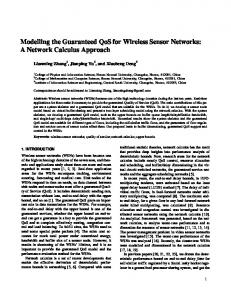
3.1.1 The Hardware Stereotype Classes Many typical hardware classes are used in WSN nodes such as radio, LEDs, and ADC modules. As an example, let us take a specific ADC module called the MDA used in the crossbow motes for capturing data. This MDA module has a MDA interface component that is captured in our design as a UML class.
The behaviour of the MDA class is captured by using state-chart (see Figure 1). The state-chart contains the triggered operation called sensor_on, which captures the behaviour of the TinyOS operation read. Once the method sensor_on is called, the state diagram changes the state from Idle to the ADC On state to model the action of sensing. The application stays in this state for 250 ms and then triggers the event readDone. The time parameter 250 is calculated based on real time measurements for the sensor behaviour in (Zheng, 2010). This state chart also captures the MDA component’s capability to turn the sensor’s excitation on and off.
Figure 1 : MDA Hardware Component
3.1.2 The Middleware Stereotype Classes The middleware stereotype classes are used to capture any operating system middleware components. The UML captures the methods, parameters, and the events of the middleware component in the same manner as the hardware components are captured. As an example for the captured components: the routing components, sending components, and dissemination components.
3.2 The TinyOS Component Wiring Pattern TinyOS has a group of implemented modules, which ease accessing common hardware and software
components. Each component has a group of interfaces which are labelled as inputs or outputs. TinyOS uses a concept known as wiring to associate an application module with a particular instance of an interface. For example in the following NesC statement, myApp.RadioControl -> ActiveMessageC The statement associates the application component RadioControl to the TinyOS interface ActiveMessageC. ActiveMessageC is a tinyOS module which interacts with the link layer of a radio unit. Therefore, the application component RadioControl has access to the methods and the event handles which were developed for the wireless transmitter. At a designer level, the concept of tinyOS wiring resembles an interface specification. This concept can be captured using a Composite Class, which captures the internal system objects, the associations between the system classes, and the collaboration of the interconnected elements of the modelled system. The Composite Class supports the creation of a Class Part. The Class Part is an instance of a class in another class and is used to capture the interface between two classes, which are associated to each other in the Composite Class. When the Class Part is created, the Class Part name is change based on the target class name. For example, for a class named database its instance in a composite class is changed to itsdatabaseClass (see Figure 2). A Composite Class is used to capture the instance of node’s hardware components, software components instances, and the associations between these components to the application, which reflect the component wiring design pattern. Moreover, the designer has to create multiple Class Parts for the same class. With this approach, the tinyOS-wiring concept can be captured using the language independent UML composite class structure.
3.3
Application Synchronization Pattern
Many WSN applications are similar to embedded software and therefore are written leveraging eventbased OS or are designed in an event-based form of design. In the case of TinyOS an application relies on signalling events either from timers or middleware or hardware components after finishing a computation process. After the event is signalled, the application follows the computation steps coded in an event handler method.
2009). The system consists of a wireless node connected to a RFID reader as well as a handheld device to communicate with the RFID system. The handheld contains an RFID tag with the handheld’s node ID programmed into it. The purpose of outfitting each wireless node with an RFID tag is to help identify individual WSN nodes that a handheld device might want to directly communicate with. This feature is primarily useful when having to debug or configure a node directly. The RFID add on also supports validation and authentication of the handheld device. Figure 2 : RFID Class Diagram
This same approach has been used to capture the event in UML. The event is triggered either by, a timer or one of the stereotyped class state diagrams. The event translates the state chart from the Idle state to a main state. The main state contains substates which capture the steps of the event handler. After the state is executed, the system returns to Idle and waits for the event to be triggered again. The event based nature of an embedded OS leads to the possibility of signalling any event at any instance based on the hardware computation time. In order to capture this design pattern, the AND state has been used. The AND state runs the sub-states concurrently. Therefore, the application state chart is ready anytime to be signalled by any event captured in the state machine. Some typical events which are used in WSNs are signalled by the following components: Timers: Timers generally control the flow of the entire application. For instance, once the sensing timer is fired, the application calls the sensors to read the temperature RFID: RFID signals events scanDone once the tag scanning is done. Routing Protocol: The routing protocol signals an event once the node starts to send the routing messages to the neighbour nodes.
4 APPLYING THE UML MODEL PATTERNS TO WSN-RFID CASE STUDY This section shows how the proposed WSN UML patterns are used to capture a software system called WSN-RFID system. The UML model patterns were developed in IBM Rational Rhapsody (IBM, 2000-
4.1 WSN-RFID Hardware and Middleware Components and Wiring The hardware stereotype classes are defined for the components RFID and the LEDs. The stereotype class has an animated state chart to capture the behaviour of the interface modules. For instance, the state diagram for the RFID is shown in Figure 3; The RFID module offers the connection, tag scan, sending methods. Those methods are used by the application to create the connection to the tag scanner, trigger the scanning process, and sending the information to a central node. The middleware modules used in WSN-RFID are DatabaseC, Connection. AMSenderC.UML classes are used to capture the behaviour of those classes in the same manner as mentioned before.
4.2 WSN-RFID Application Synchronization The events of the RFID system is captured by using the model pattern explained in Section 3.3. RFID Application is captured by using the AND state. All the states of the application is waiting at the state Idle. Once the event is signalled, the event causes the transition from Idle to the event handler. For instance, once the event receive is signalled, the statchart starts to execute the states in the ReceiveMessage main state which contains, leds_s2, checkMessage and followed by TriggerScan process which triggers the tag scanning process. The scan process implementation is captured in RFID hardware component as explained in section4.1. Once the scan process is finished, the RFID statechart signals an event scanDone, which is captured in the application state-chart (see Figure 3 and Figure 4).
hardware components. In the future we plan to extend the use of animated state diagrams to analyse the power consumption of WSN software and middleware components. This paper also presents a set of design patterns that can assist in the development of a WSN. These WSN design patterns describe best practices regarding the specification of WSN interface components and their behaviour. In the future we intend to use these design patterns in the development of additional WSN software.
6 ACKNOWLEDGEMENTS The authors would like to thank the Natural Sciences and Engineering Research Council of Canada (NSERC) for funding this research. Figure 3: RFID Class State diagram
REFERENCES
Figure 4 : Application State-Chart
5 CONCLUSION AND FUTURE WORK This paper presents a UML approach to modelling a WSN, using class and state diagrams, in order to perform power analysis during the design stage of development. Moreover, the paper demonstrates the capability of animated state diagrams to capture the interaction between the WSN application software, the middleware and the
Chen, R., Sgroi, M., Lavagno, L., Martin, G., Sangiovanni-Vincentelli, A., Rabaey, J., 'Embedded System Design using UML and Platforms', in E (ed.), System Specification & Design Languages, Springer US. Demaille, A, Peyronnet, AS & Sigoure. 2006, 'Modeling of sensor networks using XRM.', In Proc. of 2nd Int. Symp. on Leveraging Applications of Formal Methods, Verification and validation. IBM 2000-2009, 'Rational Rhapsody User Guide', IBM. Zheng, J., Elliott, C., Dersingh, A., R. Liscano, R., Eklund, M. 2010, 'Design of a Wireless Sensor Network from an Energy Management Perspective', Communication Networks and Services Research Conference (CNSR). Jacoub, J.K. , Liscano, R., Bradbury, J.S. 2012, 'Assessment of Software Modeling Techniques for Wireless Sensor Networks: A Survey', Sensors & Transducers Journal, vol 14-2, pp. 18-46. Levis, P,GD 2009, TinyOS Programming, Combridge University Press. Losilla, F., Vicente-Chicote, C., lvarez, B B., Iborra, A., Sánchez, P. 2007, 'Wireless sensor network application development; An architecturecentric mde approach', In Software Architecture, vol 4758, pp. 197-194. Mozumdar, M., Gregoretti, F., Lavagno, L., Vanzago, L.,and Olivieri, S. 2008, 'A framework for modeling, simulation and automatic code generation of sensor network application', In Proc. of 5th IEEE Comm. Soc. Conf. on Sensor, Mesh and Ad-Hoc.