performance in terms of network lifetime, energy efficiency and throughput ...... ACM workshop on Performance monitoring and measurement of hetero- geneous ...
Underwater Wireless Sensor Network’s Performance Enhancement with Cooperative Routing and Sink Mobility A. Umar1 , M. Akbar1 , S. Ahmed1, N. Javaid1,2, Z. A. Khan3 , U. Qasim4 1 EE
Dept, COMSATS Institute of Information Technology, Islamabad, Pakistan COMSATS Institute of Information Technology, Islamabad, Pakistan 3 Internetworking Program, FE, Dalhousie University, Halifax, Canada 4 University of Alberta, Alberta, Canada
2 CAST,
Abstract—Network efficiency and reliability in terms of high throughput, energy conservation, low bit error rate (BER) and reduced delay are pre-requisites for many applications in Underwater Wireless Sensor Networks (UWSNs). However, distinctive features of UWSNs like low available bandwidth, large propagation delay, highly dynamic network topology, and high error probability pose many challenges for devising efficient and reliable communication protocols. In this paper, we therefore propose a protocol that focuses on enhancing network reliability and efficiency using cooperative routing and sink mobility. Many cooperative communication protocols have been developed which investigate the physical and MAC layer aspects to improve link efficiency in harsh underwater environment, however, at network layer, it is still unexplored. Similarly, cooperative routing is not yet collaborated with sink mobility. In this paper, Cooperative routing is implemented at network layer along with sink mobility. Potential relay and destination nodes for cooperative routing are selected on the basis of their depth as well as residual energy information. Data from source node is forwarded towards the destination node via relay nodes in a cooperative manner. Sink mobility further improves the results by directly gathering data from nodes. Based on the comprehensive simulations implemented in MATLAB, we observe that our scheme improves the performance in terms of network lifetime, energy efficiency and throughput along with reducing delay and BER.
I.
R ELATED W ORK
Taking advantage of the broadcast nature of wireless transmission, cooperative communication has been proposed as a powerful alternative to reduce fading and other link impairments, where transmitted signal can be overheard by many unintended sensor nodes [1], [2]. Some related work presented in this domain is presented here An innovative physical layer solution involving cooperative communication is given in [2], where outage probability and capacity expressions are derived for cooperative multicarrier UAC systems with AF and DF relaying. Further, they propose a receiver design to mitigate the degrading Doppler effects. In [3], Cooperative UnderWater Acoustic Multiple Input Single Output (CUWA-MISO) using DF is proposed where each node of network uses nearest adjacent node as a virtual antenna in a cooperative manner. It improves the system performance with the help of spatial diversity. Luo et al. [4], explored cooperation at MAC layer and proposed a
distributed MAC protocol, that is, Coordinated Transmission MAC (CT-MAC) for underwater MIMO based network uplink communication. The scheme also addresses long propagation delay and collision among control packets in UAC. Authors in [5] suggested that channel efficiency is improved by applying asynchronous cooperative transmission for three dimensional UWSNs. Two typical forwarding schemes: AF and DF are implemented, analyzed and compared. In COoperative Best Relay Assessment (COBRA) [6], a relay selection criterion for underwater cooperative acoustic networks is developed. COBRA minimizes the One-way Packet Transmission (OPT) time. The best relay selection algorithm is used here. In [7], authors consider cooperative scheme with a design aspect from the physical layer to the network layer, leading to the efficient operation and reduced transceiver’s complexity. It enhances the reliability by providing diversity gains through intermediate relay nodes. Improving network lifetime is a fundamental challenge for UWSNs. One possible solution exists in making use of sink mobility. Some of the protocols presented in this domain are An adaptive strategy is proposed by authors in [1] that guarantees minimum energy consumption by enforcing sink redeployment. Sink redeployment decision is based on routing information. When there is high mobility, more nodes are switching to use higher power levels for communication. To overcome this, a sink redeployment procedure starts to find the optimal new location of surface sink. A coordination scheme using sink mobility for data gathering in UWSN is proposed by authors in [8] that achieve energy efficiency and communication reliability. The shortest wakeup time and optimal period of sleep time for sensor nodes are investigated. In [9], an underwater application model for collecting detailed data with multiple Mobile Sinks (MSs) to get high temporal resolution capability is presented. In [10], sink mobility is used to improve network lifetime in three dimensional UWSNs. Radius of the monitored region grows in three dimensional networks, hence, improved lifetime and efficient energy utilization of nodes are of greater concern. MobiRoute is defined by authors in [11], it supports sink mobility. Its favorable features are sinks controlled and predictable mobility and pause time. Autonomous Underwater Vehicle (AUV) aided Underwater Routing Protocol (AURP) [12] minimizes total number of data
transmissions by using multiple mobile sinks or AUVs as relay nodes, which results in a high packet delivery ratio and low energy consumption. In AUV aided Energy Efficient Routing Protocol for Underwater Acoustic Sensor Network (AEERP) [13], a mobile sink collects data from gateway nodes. Among all the nodes, gateway node communicates with mobile sink. Gateway nodes are selected on the basis of their residual energy. In [14], a novel routing protocol called Depth-Based Routing (DBR) is proposed that uses the depth of the sensor nodes as a routing metric and forwards data towards sink using the greedy approach. In [15], an energy efficient routing protocol, named Energy-Efficient Depth-Based Routing (EEDBR) is presented. EEDBR utilizes depth as well as residual energy of sensor nodes in order to improve the network lifetime. In IAMCTD [16], a forwarding function based routing scheme is proposed. It is a novel network prototype in localizationfree and flooding based routing for underwater applications.It achieves energy conservation. II.
M OTIVATION
In UWSNs, reliability and robustness of retrieved information, reduced delay, low Bit Error Rate (BER), high throughput and energy conservation are of great concern. Novel routing solutions are therefore required for efficient and improved data forwarding. Cooperative communication achieves high throughput along with reliable data transfer by reducing BER, however, it results in high propagation delay. Sink mobility reduces propagation delay and achieves energy conservation, however, it does not cater for reliability of retrieved information. Many protocols involving cooperative communication are developed by investigating physical and Medium Access Control (MAC) layer aspects; however, at network layer it is still unexplored. Similarly, the mechanism of implementing sink mobility along with cooperative routing in the network is still unattended. Therefore, this work focuses on cooperative routing along with sink mobility in UWSNs because we are interested in taking advantage of their positive aspects along with minimizing their drawbacks. III.
PROPOSED SCHEME
In this section we present our work. The following subsections give a detailed view of our scheme. A. Network Architecture Our network is composed of sensor nodes, MSs and surface station. Numerous sensor nodes are randomly deployed in the area to be monitored. MSs are deployed at different depths within water. Sensor nodes and MSs are equipped with acoustic modems. MSs gather data from sensor nodes and forward it to surface station which is present on water surface. Surface station is equipped with both acoustic as well as radio modem for communication with MSs and on-shore data center. As radio communication is 5 times faster than acoustic communication, a data packet once received at any MS is considered delivered to the on-shore data center. Cooperative routing is implemented as both SRC and MRC. Two different sink mobility patterns are considered i.e. elliptical and horizontal. While following an elliptical mobility pattern, depth
of MSs varies constantly whereas it remains fixed throughout the network lifetime when MSs follow a horizontal mobility pattern. B. Channel Model Each source node modulates data using BPSK modulation scheme. Channel over which this modulated data is transmitted suffers Rayleigh fading and AWGN noise. Equations (1-5) [17] describe the relationship between transmitted and received signals by the source and relay node(s) where Xs is the origional signal. Ysd , Ysr1 , and Ysr2 are signals received at destination node and relay node(s) via source node respectively. Yr1d and Yr2d are signals received at destination node via relay node(s). nsd , nsr1 , nsr2 are channel noise existing over source to destination and relay node(s) links. nr1d and nr2d represent channel noise existing over relay node(s) to destination node link. gsrd , gsr1 , and gsr2 are channel gain existing over source to destination node and relay node(s) links. gr1d and gr2d represent channel gain existing over relay node(s) to destination node link. Ysd = Xs gsd + nsd
(1)
Ysr1 = Xs gsr1 + nsr1
(2)
Ysr2 = Xs gsr2 + nsr2
(3)
Signals received at the destination node via relay node(s) are Yr1d = Ysr1 gr1d + nr1d
(4)
Yr2d = Ysr2 gr2d + nr2d
(5)
The three independently faded copies of same data are combined at destination using diversity combining technique. C. Knowledge Acquisition Phase In this phase all nodes share their depth and residual energy information with each other. D. Network Initialization Phase Because of the knowledge acquisition phase, all nodes are aware of each others depth. During the network initialization phase nodes find their neighbors. Neighbors selection is based on transmission range, residual energy and depth information. A node is selected as neighbor if it is having sufficient residual energy and is laying at comparatively similar or lesser depth. Depth threshold is used to avoid flooding and it is selected on the basis of number of a node’s neighbors. In this way, global knowledge of network density is not required and nodes adapt their depth threshold based on their alive neighbors. During this phase, each node is advised to keep on identifying its alive neighbors at regular intervals to adapt the depth threshold accordingly. Nodes forward their data by utilizing this depth threshold value and residual energy information of neighboring nodes. E. Depth Threshold Selection Process During the network initialization phase, each node is advised to keep on identifying its alive neighbors at regular intervals to adapt the depth threshold accordingly. Depth threshold selection process is shown in algorithm 1. The three optimal values of depth threshold (Dth1 , Dth2 and Dth3 ) are adapted on the basis of number of alive neighbors of a node.
Algorithm 1 Depth Threshold Selection R ← Current round Rmax ← Maximum number of rounds N ← Number of a node’s neighbors Dth ← Depth threshold Dth1 , Dth2 , Dth3 ← Optimal values of depth threshold (Dth1 > Dth2 > Dth3 ) for R = 1 : 1000 : Rmax do if N ≥ 9 then Dth = Dth1 else if 9 < N ≥ 5 then Dth = Dth2 else if N < 5 then Dth = Dth3 end if end for
F. Critical-range Based Data Sensing Traditional routing schemes consume surplus energy because of transmission of redundant data and retransmission of critical data. We exploit threshold based data sensing. This threshold is specified on an application basis. Algorithm 2 depicts the involved procedure. After network initialization, sensor nodes start sensing the specified environmental attribute. If the sensed value is greater than or equal to Hth , flag field of the data packet is set to 1. Then, this data packet is forwarded if source node’s residual energy Ri is sufficient for transmission. The other scenario is that if the sensed value is lesser than Hth but greater than or equal to Sth . In this scenario, source node sets flag field of data packet to 0 and performs forwarding if it is having enough residual energy Ri . Here, flag field is appended to the basic packet structure in order to indicate severity of the sensed attribute, so that appropriate measures can be adopted at the on-shore data center.
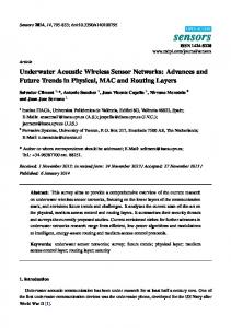
G. Data Routing Phase via Cooperative Routing toward MSs Data generated as a result of sensing process is forwarded to in-range MS. On reception of this data, MS commands the source node to avoid further flooding of this data. In absence of MS, source node have to forward it to relay node(s) and destination node. For any source node, relay node(s) lie within the depth threshold boundary and destination nodes lies outside the depth threshold boundary. Our protocol assumes that relay nodes are in perfect synchronization with each other. Two different sink mobility patterns result in different data routing scenarios. Scenario 1: When MSs follow an elliptical mobility pattern their depth varies continuously. It varies between high to low when MS is moving in a clockwise fashion and between low to high when MS moves in a counter-clockwise fashion. In this scenario, destination node and relay node(s) for cooperative routing are selected on the basis of residual energy only. A node laying within the depth threshold boundary is selected as relay node if it is having comparatively highest residual energy. Whereas, destination node is the one that lies outside the depth threshold boundary and has highest residual energy. Hence, in this scenario cooperative partner nodes can be present at lower or higher depth as compared to source node. Data routing is shown in fig. 1. On the basis of above described criteria sensor nodes A and C find relay and destination nodes and perform data forwarding. Node A forwards data towards higher depth and node C towards lower depth. In both these cases data will be collected from destination nodes by MSs. Node B is in direct transmission range of MS, hence it forwards its data towards MS via a relay node in a cooperative manner.
The proposed scheme is applicable for many scientific applications that observe the environment; from geological processes on the ocean floor, to water characteristics (temperature, salinity, oxygen level, bacterial and other pollutant content, dissolved matter, etc.) to counting or imaging animal life (microorganisms, fish or mammals) [18]. Algorithm 2 Data Sensing and Routing S ← Sensed attribute Hth ← Hard threshold Sth ← Soft threshold P ← Data packet Ri ← Residual energy F ← Flag if S ≥ Hth AND Ri > 0 then send P set F = 1 else if Sth ≤ S < Hth AND Ri > 0 then send P set F = 0 else no transmission end if
Fig. 1. Cooperative routing implementation in scenario 1 (elliptical sink mobility pattern)
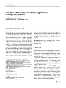
Scenario 2: When MSs follow a horizontal mobility pattern their depth remain fixed throughout the network lifetime. Hence in this scenario, destination node and relay node(s) are selected on the basis of residual energy as well as depth as data is to be routed towards lower depth. A node laying within the depth threshold boundary is selected as relay node if it is lying at comparatively lesser or equal depth and possesses highest residual energy. Whereas, destination node is the one that lies outside the depth threshold boundary and has lowest
depth. Hence, in this scenario cooperative partner nodes can be present at lower depth only. Data routing is shown in fig. 2. On the basis of above described criteria sensor nodes D and F find relay and destination nodes and perform data forwarding. Both nodes forward data toward lower depth. Node E is in direct transmission range of MS, hence it forwards its data towards MS via a relay node in a cooperative manner.
mobility pattern consider depth and residual energy of forwarding node. Whereas, in SRC and MRC with elliptical sink mobility pattern, only residual energy is considered. Following evaluation metrics are considered: •
Alive nodes: It shows the number of nodes that have residual energy sufficient for data transmission.
•
Average energy consumption: It is the average energy consumed by all alive nodes per round.
•
Throughput: It is the total number of packets received at sink per round.
•
End-to-end delay: It represents the average time taken by a packet to travel from source to sink.
•
Packet drop: It shows the number of dropped packets out of total number of packets generated per round.
•
Packet Acceptance Ratio(PAR): It is defined as the ratio of total no. of packets received at the sink to the total no. of packets sent to the sink per round.
•
BER: It is the number of received bits that has been altered due to noise, interference, distortion etc. BER is the ratio of number of erroneous bits divided by the total number of transferred bits during a studied time interval. It is a unit less performance measure, often expressed as a percentage.
Fig. 2. Cooperative routing implementation in scenario 2 (horizontal sink mobility pattern)
Network life Time
The routed data packet is composed of header and payload. Header contains the control information which is necessary for data routing whereas payload is the actual data to be transmitted. Format of data packet that is used in our scheme is shown in fig. 3
250
200
Alive Nodes
Fig. 3.
DBR EEDBR IAMCTD SRC−elliptical MRC−elliptical
150
100
Format of data packet 50
IV.
R ESULTS
AND DISCUSSION
We perform simulations of our proposed scheme in MATLAB and compare it with DBR, EEDBR and IAMCTD. Sensor nodes are 225 in number and they are randomly deployed in underwater environment at an area of 500 m x 500 m. Four MSs are deployed in water at different depths and they are following elliptical and horizontal mobility patterns. Each node is equipped with an initial energy of 10 J and is having a fixed transmission range of 100 m. Size of data packet is 200 byte. The acoustic modem used is LinkQuest UWM1000 [19] which has a bit rate of 10 kbps. Power consumption involved in transmitting, receiving and idle modes is 2W, 0.1W and 10mW respectively. DBR considers depth, EEDBR considers depth along with residual energy and IAMCTD considers SNR and depth of the forwarding node as an ultimate forwarding node determining factor. In our scheme, SRC and MRC with horizontal sink
0
0
500
1000 Rounds
1500
2000
Fig. 4. Comparison of alive nodes in the network with elliptical sink mobility pattern
As shown in fig. 4 and fig. 5, in DBR and EEDBR, there is a small stability period, however, the instability period is much better in DBR as compared to EEDBR as there is a gradual increase in network energy consumption in DBR. When the network becomes sparse, number of neighbors decreases quickly causing network instability. In DBR, low-depth nodes die at an earlier stage due to high data forwarding rate and constant depth threshold. It neglects residual energy of nodes as well as SNR thus badly affecting networks throughput. Number of dead nodes sharply increases in EEDBR as there is high load on the nodes with sufficient residual energy. The life time of IAMCTD is more than SRC and MRC because in
Network life Time
Total Energy consumption of network
250
9 DBR EEDBR IAMCTD SRC−horizontal MRC−horizontal
Total Energy consumption in joules
Alive Nodes
200
DBR EEDBR IAMCTD SRC−horizontal MRC−horizontal
8
150
100
50
7 6 5 4 3 2 1
0
0
500
1000 Rounds
1500
0
2000
0
500
1000 Rounds
1500
2000
Fig. 5. Comparison of alive nodes in the network with horizontal sink mobility pattern
Fig. 7. Comparison of total energy consumption of network with horizontal sink mobility pattern
IAMCTD only source node is transmitting data to its next hop neighbor. However, in SRC and MRC data is transmitted from source node as well as relay node(s) to next hop (destination node). So it is consuming 2 (SRC) to 3 (MRC) times more transmission energy than IAMCTD. This shows the tradeoff between network lifetime and reliability.
to IAMCTD because of cooperative transmission being performed. As the network starts, nodes become active and start the sensing and transmission process. All nodes are alive and each node finds its relay node(s) and destination node and performs transmission and reception process because of which energy consumption is increased. After about 100 rounds, the rate with which nodes are dying increases and energy consumption decreases. The reason behind this decreased energy consumption with increasing number of rounds is that now nodes fail to find relay nodes because of reduction in network density. As a result, the chances of cooperative transmission being performed by any source node are reduced which in turn reduces energy consumption and most of the transmissions are performed to only the MS or next hop node(in absence of MS and relay node) only.
Total Energy consumption of network 8 DBR EEDBR IAMCTD SRC−elliptical MRC−elliptical
Total Energy consumption in joules
7 6 5 4
Throughput
3
100
2
90 80
0
500
1000 Rounds
1500
2000
Fig. 6. Comparison of total energy consumption of network with elliptical sink mobility pattern
DBR shows better energy consumption management than EEDBR as shown in fig. 6 and fig. 7. In DBR, energy consumption increases steadily as number of eligible neighbor drops off with the network density. In EEDBR, energy consumption is higher than other techniques due to frequent selection of high energy nodes. IAMCTD balances the energy consumption by proper forwarder selection and mobility patterns of courier nodes. In IAMCTD there is higher energy consumption than the other protocols in the later rounds because of uniform network density. However, in SRC and MRC there is high energy consumption involved as compared
Packet Received at Sink
1 0
DBR EEDBR IAMCTD SRC−elliptical MRC−elliptical
70 60 50 40 30 20 10 0
0
500
1000 Rounds
1500
2000
Fig. 8. Comparison of packets received at MSs with elliptical sink mobility pattern
Fig. 8 and fig. 9 show throughput. Throughput of DBR and EEDBR declines very quickly due to the quick fall in
Throughput
DELAY 0.7 DBR EEDBR IAMCTD SRC−horizontal MRC−horizontal
Packet Received at Sink
100
80
60
40
20
0
0
500
1000 Rounds
1500
Average End−to−End Delay per round of Network
120
0.6
0.5
0.4
0.3
0.2
0.1
0
2000
Fig. 9. Comparison of packets received at MSs with horizontal sink mobility pattern
network density, which is unsuitable for both delay-tolerant and delay-sensitive applications. The throughput of IAMCTD, SRC and MRC demonstrate the amount of threshold-optimized data for responsive networks. In these schemes unnecessary data transmissions are avoided that results in lower throughput as compared to DBR and EEDBR. In our schemes, throughput steadily decreases due to maintenance of network density and low energy consumption. Throughput is higher in SRC and MRC with horizontal sink mobility pattern as compared to SRC and MRC with elliptical sink mobility pattern and IAMCTD. With horizontal sink mobility pattern, chances of packets being received at the sink are more as compared to elliptical sink mobility pattern. Although with the elliptical mobility pattern of MS the BER is much reduced, however, sink availability to nodes is also reduced as compared to horizontal mobility pattern which in turn reduces packet reception at sink.
DBR EEDBR IAMCTD SRC−horizontal MRC−horizontal
0
500
1000 Rounds
1500
2000
Fig. 11. Comparison of average end-to-end delay with horizontal sink mobility pattern
As shown in fig. 10 and fig. 11, in DBR, delay is much higher in initial rounds due to distant data forwarding of high-depth nodes because of energy depletion of mediumdepth nodes. Delay decreases gradually with the sparseness of the network. In EEDBR, delay sharply increases at about 300 rounds as the network becomes scattered causing data forwarding at maximum distance. In EEDBR higher delay is caused due to prioritization of residual energy. End-toend delay of network in iAMCTD is lesser than all other techniques because there is a minimum possible time lag due to consideration of signal quality and depth difference between sender and receiver nodes. In SRC and MRC signal quality is not considered while selecting next hop and relay nodes because of which delay is comparatively higher as compared to IAMCTD. Along with this, SRC and MRC involve multiple phases of communication i.e., from source to next hop, from source to relay node(s) and from relay node(s) to next hop node, hence delay is induced because of this multiple phase process.
DELAY Network Quality
DBR EEDBR IAMCTD SRC−elliptical MRC−elliptical
0.8 0.7
140 DBR EEDBR IAMCTD SRC−elliptical MRC−elliptical
120
0.6 100 0.5 Packet Drop
Average End−to−End Delay per round of Network
0.9
0.4 0.3 0.2
80
60
40
0.1 20 0
0
500
1000 Rounds
1500
2000
Fig. 10. Comparison of average end-to-end delay with elliptical sink mobility pattern
0
Fig. 12.
0
500
1000 Rounds
1500
2000
Comparison of packet drop with elliptical sink mobility pattern
Network Quality
PACKET ACCEPTANCE RATIO 1 DBR EEDBR IAMCTD SRC−horizontal MRC−horizontal
120
Packet Drop
100
80
60
40
20
0
Fig. 13.
0
500
1000 Rounds
1500
Packets Received at sink/Packets Sent to sink
140
0.8 0.7 0.6 0.5 0.4 0.3 0.2 0.1 0
2000
Comparison of packet drop with horizontal sink mobility pattern
Fig. 12 and fig. 13 show packet drop. High packet drop of DBR and EEDBR is due to single poor link having BER greater than 50 percent most of the time. IAMCTD takes into account link quality in terms of SNR while selecting the forwarder node because of which packet drop is lowest. SRC and MRC drop packets only when no link (direct link to the next hop node and via relay node(s) to next hop node) is available or BER of combined signal received at next hop node is greater than 50 percent. Packet drop is higher in SRC and MRC with horizontal mobility pattern of sinks as compared with elliptical mobility pattern of sinks. Whenever the condition specified by the Hth and Sth is met, packets are generated by nodes. Sink only accepts those packets that are having a BER less than 50percent and remaining are dropped. In SRC/MRC-horizontal although the chances of packets being received at the sink are more as compared to SRC/MRCelliptical but the BER is higher in this scenario. Due to high BER packet drop is higher in SRC/MRC-horizontal.
DBR EEDBR IAMCTD SRC−horizontal MRC−horizontal
0.9
Fig. 15.
0
500
1000 Rounds
1500
2000
Comparison of PAR with horizontal sink mobility pattern
the lowest PAR as the number of packets received at sink in both these scenarios is small due to single poor link having high BER for most of the time. IAMCTD is having highest PAR even if its BER is high because it selects forwarder nodes on the basis of SNR. however, as BER is high, the received information is least reliable as compared to SRC/MRC. Along with this, in IAMCTD 4 surface sinks and 4 courier nodes are present which increase chances of packets being received, increasing PAR. In SRC/MRC information is more reliable and accurate because of having least BER. The PAR is higher in SRC/MRC-horizontal as the number of packets received at sink in this scenario is higher. Bit Error Rate 0.5 DBR EEDBR IAMCTD SRC−elliptical MRC−elliptical
0.45 0.4 0.35
PACKET ACCEPTANCE RATIO
0.3 DBR EEDBR IAMCTD SRC−elliptical MRC−elliptical
0.8 0.7
BER
Packets Received at sink/Packets Sent to sink
0.9
0.25 0.2 0.15
0.6 0.1 0.5
0.05
0.4
0
0.3 0.2
Fig. 16.
0
500
1000 Rounds
1500
2000
Comparison of BER with elliptical sink mobility pattern
0.1 0
Fig. 14.
0
500
1000 Rounds
1500
2000
Comparison of PAR with elliptical sink mobility pattern
PAR is shown in fig. 14 and fig. 15. DBR and EEDBR have
Fig. 16 and fig. 17 show BER. In DBR, EEDBR and IAMCTD BER is very high. Reason for this high BER is availability of a single link having poor link quality. In SRC and MRC, BER is reduced because of availability of multiple links. If one link is having any link impairment then data can be received via alternate link(s) with integrity. In SRChorizontal, BER varies between 10-14 percent, whereas, in
Bit Error Rate 0.5 DBR EEDBR IAMCTD SRC−horizontal MRC−horizontal
0.45 0.4
[2] [3]
0.35
BER
0.3
[4]
0.25 0.2 0.15
[5]
0.1 0.05 0
Fig. 17.
[6] 0
500
1000 Rounds
1500
2000
[7]
Comparison of BER with horizontal sink mobility pattern [8]
SRC-elliptical it varies between 4-5 percent. Similarly in MRC-horizontal BER varies in the range of 1 to 2 percent, whereas, in MRC-elliptical BER remains fixed and is only 1 percent. BER is reduced to half by the use of elliptical sink mobility pattern. It indicates that reliability of information is more in this scenario. V.
C ONCLUSION
AND
F UTURE W ORK
In this paper we have proposed a scheme for enhancing the performance of UWSNs via cooperative routing and sink mobility. The proposed scheme is devised by taking into account depth and residual energy as routing metrics. It operates in different phases, namely knowledge acquisition phase, network initialization phase and threshold based data sensing and routing phase. During the knowledge acquisition phase, nodes share their depth and residual energy information. During the network initialization phase, each node is advised to calculate the number of its alive neighbors at regular intervals to adapt the depth threshold accordingly. In threshold based data sensing and routing phase, nodes sense data on the basis of the defined threshold and forward it to in-range mobile sink or cooperative partner nodes. We implemented our proposed work in MATLAB and evaluated its performance by comparing it with DBR, EEDBR, and IAMCTD with respect to network lifetime, throughput, PAR, energy consumption, end-to-end delay and BER. Based on the comprehensive simulation, we observed that our work contributes to the performance improvement in terms of network lifetime, throughput and PAR along with reduced energy consumption and delay as compared to DBR and EEDBR. Least BER is achieved as compared to all three schemes i.e. DBR, EEDBR and IAMCTD which makes our scheme most reliable of all. As a future work, we are interested in incorporating SNR along with depth and residual energy as a selection criterion of relaying nodes so that improved results as compared to IAMCTD with respect to all parameters can be achieved. R EFERENCES [1]
M. Al-Bzoor, Y. Zhu, J. Liu, R. Ammar, J. H. Cui, and S. Rajasekaran, “An adaptive surface sink redeployment strategy for Underwater Sen-
[9]
[10]
[11]
[12]
[13]
[14]
[15]
[16]
[17]
[18]
[19]
sor Networks”, IEEE Symposium on Computers and Communications (ISCC), 2013. S. Al-Dharrab, and S. Ibrahim, “Cooperative Communication over Underwater Acoustic Channels”, Diss. University of Waterloo, 2013. M. J. Jannati, A. D. Aref, and V. T. Vakily, “Implementation of cooperative virtual MISO communication in underwater acoustic wireless sensor networks”, International Journal of Computer Science Issues (IJCSI) 8, no. 4, 2011. Y. Luo, L. Pu, Z. Peng, Z. Zhou, and J. H. Cui, “CT-MAC: a MAC protocol for underwater MIMO based network uplink communications”, Proceedings of the Seventh ACM International Conference on Underwater Networks and Systems, ACM, 2012. P. Wang, L. Zhang, and V. O. K. Li, “Asynchronous cooperative transmission for three-dimensional underwater acoustic networks”, IET Communications, 7, no. 4, pp. 286-294, 2013. D. D. Tan, T. T. Le, and D. S. Kim, “Distributed cooperative transmission for underwater acoustic sensor networks”, IEEE Wireless Communications and Networking Conference Workshops (WCNCW), 2013. Y. Luo, L. Pu, Z. Peng, Z. Zhou, J. H. Cui, and Z. Zhang, “Effective Relay Selection for Underwater Cooperative Acoustic Networks”, IEEE 10th International Conference on Mobile Ad-Hoc and Sensor Systems (MASS), 2013. R. Su, R. Venkatesan, and C. Li, “A new node coordination scheme for data gathering in underwater acoustic sensor networks using autonomous underwater vehicle”, IEEE Wireless Communications and Networking Conference (WCNC), 2013. J. Wang, D. Li, M. Zhou, and D. Ghosal, “Data collection with multiple mobile actors in underwater sensor networks”, 28th International Conference on Distributed Computing Systems Workshops, (ICDCS’08.), 2008. S. Shen, A. Zhan, P. Yang, and G. Chen, “Exploiting Sink Mobility to Maximize Lifetime in 3D Underwater Sensor Networks”, IEEE International Conference on Communications (ICC), 2010. J. Luo, J. Panchard, and M. Piorkowski, “Mobiroute: Routing towards a mobile sink for improving lifetime in sensor networks”, Distributed Computing in Sensor Systems, Springer Berlin Heidelberg, pp. 480-497, 2006. S. Yoon, A. K. Azad, H. Oh, and S. Kim, “AURP: An AUV-aided underwater routing protocol for underwater acoustic sensor networks”, Sensors, 12, no. 2, pp. 1827-1845, 2012. A. Ahmad, A. Wahid, and D. Kim, “AEERP: AUV aided energy efficient routing protocol for underwater acoustic sensor network”, 8th ACM workshop on Performance monitoring and measurement of heterogeneous wireless and wired networks, 2013. Yan, H., et al. “DBR: depth-based routing for underwater sensor networks,” NETWORKING 2008 Ad Hoc and Sensor Networks, Wireless Networks, Next Generation Internet. Springer Berlin Heidelberg, pp. 7286, 2008. Wahid, A., et al. “An energy efficient localization-free routing protocol for underwater wireless sensor networks,” International Journal of Distributed Sensor Networks, 2012. Jafri, M. R., et al. “IAMCTD: Improved Adaptive Mobility of Courier nodes in Threshold-optimized DBR Protocol for Underwater Wireless Sensor Networks,” Broadband and Wireless Computing, Communication and Applications (BWCCA), Eighth International Conference on. IEEE, 2013. El-Darymli K. “Amplify-And-Forward cooperative relaying for a linear wireless sensor network”,IEEE International Conference on Systems Man and Cybernetics (SMC), 2010 p.106-112. Heidemann, J., et al. “Underwater sensor networks: applications, advances and challenges,” Philosophical Transactions of the Royal Society A: Mathematical, Physical and Engineering Sciences 370.1958, pp. 158175, 2012. Wills,J., et al. “Low-power acoustic modem for dense underwater sensor networks,” in Proceedings of the 1st ACM international workshop on Underwater networks, pp. 7985, ACM, 2006.