graph partitioning algorithm proposed by Olson et al. [9]. The idea is to ... Olson has shown that this problem .... [9] E. Olson, M. Walter, S. Teller, and J. Leonard.
Unsupervised Learning of 3D Object Models from Partial Views Michael Ruhnke
Bastian Steder
Giorgio Grisetti
Wolfram Burgard
Abstract— We present an algorithm for learning 3D object models from partial object observations. The input to our algorithm is a sequence of 3D laser range scans. Models learned from the objects are represented as point clouds. Our approach can deal with partial views and it can robustly learn accurate models from complex scenes. It is based on an iterative matching procedure which attempts to recursively merge similar models. The alignment between models is determined using a novel scan registration procedure based on range images. The decision about which models to merge is performed by spectral clustering of a similarity matrix whose entries represent the consistency between different models. Index Terms— object detection, model learning , range images
I. I NTRODUCTION An essential ability for a system which interacts with unstructured environments is to learn models of the surrounding objects. Whereas many researchers focused on the detection of known object models in a 3D scene, relatively little work has been done on the learning of those models. In this paper, we present an approach for unsupervised learning of object models from a set of 3D scans. One special property of our algorithm is that it operates with partial views because in 3D laser range scans typically only a part of the object is visible. To get a complete model of an object, the robot therefore either needs to travel around it or needs to combine several views of identical objects in the current scene. Our approach can be applied to a sequence of 3D scans not necessarily acquired in the same environment. If multiple instances of an object are visible in a scene from different perpsectives, our approach can construct a model even from a single scan, by merging the different individual views. Such a model contains all available structrual information of an object. Figure 1 shows a motivating example of our algorithm. Our approach proceeds in an iterative fashion by recursively merging partial point clouds representing partial views of the objects. Pairs of models are aligned by means of a novel registration algorithm based on range images. The similarity between different models is evaluated by a scoring function specifically designed to cope with incomplete views. The selection of the models to be joined is calculated according to a spectral clustering of the similarity matrix. The remainder of this document is organized as follows. We first discuss the related literature on object model learning from 3D scans. Subsequently, we present our approach. Then, we show the effectiveness of the approach with real world experiments. All authors are with the Autonomous Systems Lab, Department of Computer Science, University of Freiburg, D-79110 Freiburg, Germany {ruhnke,steder,grisetti,burgard}@informatik.uni-freiburg.de
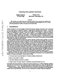
Fig. 1. In this figure, we show a motivating example of our approach. The top image shows a 3D scan acquired with our mobile robot. The partial views of objects extracted from the scan are shown in different colors. From these partial views we compute a simlarity matrix, shown in the bottom left part of the figure. Based on this similarity matrix we merge partial views to obtain the complete models illustrated in the bottom right of the figure.
II. R ELATED W ORK Whereas several researchers addressed the detection of known objects in 3D data and a variety of effective solutions have been developed, the problem of autonomously learning such models from incomplete views is still an open research issue. In the context of 3D object detection, Gelfand et al. [3] presented an approach for global registration based on integral volume descriptors, which are one-dimensional descriptors whose values depend on the volume enclosed by the local surface around a point. A branch-and-bound algorithm based on distance matrix comparisons is used to select the optimal correspondence set and align the two shapes. The comparison is made efficient by reducing the set of features based on the uniqueness of their descriptor. Johnson et al. [6] proposed to use the so-called spin-images for object detection, which are 2D representations of the surface surrounding a 3D point. Spin images have been often reported to be robust features for matching 3D data. They propose to compute a spin-image for every point in the model and every point in the scene. Computing the spin images requires to calculate the local surface normals. On point clouds these normals are typically expensive to compute and highly sensitive to the noise in the data. Correa et al. [10] proposed a variant of spin-images (spherical spin images) that simplifies the
nearest neighbor search. They define equivalence classes of spin-images by using the linear correlation coefficient. Furthermore, they compress the descriptor to a smaller dimension to speed up the comparison. Mian et al. [7] use the tensor descriptors as alternative features. To compute these tensor descriptors, they rely either on an accurate estimate of the surface normals or on the mesh structure of the data in general. Stiene et al. [11] present an object detection approach based on contours extracted from range images. Their features are based on a fast Eigen-CSS method and a supervised learning algorithm. Triebel et al. [13] use spin-images as features for an associative Markov network (AMN). The parameters of this AMN are learned from manually labeled training data. Subsequently they apply the learned AMN to label regions of a scan based on their local appearence. In a subsequent work [12] they use their AMNbased classifier to complete partial scans. This is done by partitioning the scan into contiguous regions having the same labels. These regions are likely to represent an instance of an object, which is then replaced by its model, to complete a scan. All these approaches focus on detecting instances of objects belonging to known models in the environment. In contrast to them Anguelov et al. [1] proposed a technique for learning these object models from 2D grid patches. The input to the algorithm is a set of small grid maps representing complete views of objects in a non-static environment. These grid maps are obtained by calculating differences between sets of complete grid maps acquired at different points in time. The approach seeks to compute complete models of objects from these small grid-maps. In principle this approach could be extended to operate on 3D data. However, it requires the input grids to represent complete views of the object to be learned. If only partial views of objects are visible, the complexity of the problem increases due to the difficulties in performing data association. However, in many applications a full 3D map of the environment in which all objects are completely visible is not available. Therefore, the ability to operate with partial views is highly desirable. In this paper we present an approach to learn 3D object models from a sequence of 3D laser range data. Our algorithm is able to learn a complete model of an object also from a single scan if multiple instances of the same object are simultaneously visible. III. L EARNING O BJECTS FROM 3D S CANS In this section we describe the details of our approach to learning 3D object models from a sequence of 3D scans. Each model of an object is represented as a 3D point cloud. We first give a general outline of the entire algorithm before we discuss the details of the individual steps. The overall procedure works as follows. Given a set of scans we extract regions representing views of objects. These regions are obtained by removing the background from the scene, and by grouping neighboring points into partial object views as described in Section III-A. To create a model, we
determine for each pair of views the transformation which best aligns them by means of a novel technique based on range images (see Section III-B). For each pair of object views, we then evaluate the quality of the match by using a score function specifically designed to operate with partial views of objects (Section III-C). The output of this procedure is a square consistency matrix having as many rows as the current number of models. From this matrix, we determine the current set of maximally consistent models and we join them into a single one. To determine the models to be merged, we apply an approach based on spectral clustering discussed in Section III-D. A. Generating the Partial Views from a 3D Scan The input of our procedure is a set of 3D scans. From these scans we extract a set of point clouds which represents the visible parts of the objects. To this end, we need to remove the points which belong to the background of the scene (i.e., walls, floor, etc.). This is done by fitting a set of planes in the scene, and removing the supporting points. To extract these planes we first compute the local normals of the points. Subsequently we group the neighboring points having similar normals into sets and compute the fitting plane for each of those sets. We finally remove from the scan those points which are assigned to the horizontal planes (floor) and to the vertical ones (walls) having an area bigger than a given threshold. In our experiments this threshold was set to (0.25 m2 ). To obtain the partial views from the remaining points in the scans we group them by connecting the neighbors. This procedure returns a set of small point clouds {Vi }, each of which represents a partial view of a candidate object, observed from a position pi . Our approach seeks to obtain complete models of objects by merging either partial views or incomplete models. After the partial views have been extracted, all the subsequent operations are performed on (k) models.nA model is defined as a collection of point o M (k) (k) clouds Vi . Let pi be the viewpoint from which the (k)
object view Vi
has been acquired.
B. Fast Matching of Partial 3D Models Based on Range Images An essential step to determine whether two models can be merged is to calculate the potential alignments between them. In this section we present, a procedure to efficiently compute the transformations which aligns two incomplete models M(n) and M(m) . To this end, we use an approach based on range images extracted from the point clouds. Range images are compact representations of 3D data. The value of every pixel is the length of the segment which starts from the observer, passes through the image pixel and ends to the closest point in the scene. Whereas a range image of the scene depends on a specific viewpoint, arbitrary scenes can be represented by a collection of range images obtained by different viewpoints. An example of these range images is shown in Figure 2. In our current system, we apply the z-buffer algorithm [2] to
Fig. 2. Example of range images generated from a point cloud. The original point cloud (left) and range images obtained from different viewpoints (center and right). The darker a pixel of the range image is, the closer to the viewpoint.
efficiently compute a range image from an unsorted list of 3D points. Given a model M(k) , we can compute n its opoint cloud (k) , translated as the union of the original point clouds Vi (k)
according to a transformation Ti (k)
as follows:
(k) (k)
ˆ i,j = Ti xi,j . x (k) ˆ i,j x
(1) (k) Ti
Here, is point of the model M(k) , is a the transformation matrix which translates all the points of the (k) object views Vi in the reference frame of the model, and (k) xi,j is the j th point of the ith object view in the model. Our matching procedure works as follows. Let M(n) and M(m) be two models. From each of the two point clouds we sample a set of range images from different viewpoints. In our experiments we selected 12 viewpoints equally distributed around the model, starting from the original observation position. From each image in the two sets we select a set of interest points by means of an Harris corner detector [4]. We then compute for each of these interest points a set of features, which are small image patches from the neighborhood of the interest point. To achieve a certain degree of invariance w.r.t. to the distance between the object and the robot, we shift the values of the image patch according to the distance of the center of the patch. In our implementation the size of those image patches was always 6×6 pixels in the image and 30×30 cm in the world. The descriptor vector of each feature contains the values of the pixels in the patch. We then determine a set of potential correspondences between the features of the first model and the feature of the second model. As a distance metric we use the Euclidean distance between the feature descriptors. Since each feature represents a 3D point, we can align the models if we know three point correspondences [5]. To this end, we use a variant of the GOODSAC algorithm [8], i.e., we sequentially select triples of corresponding features based on their descriptor distance. Each transformation is then validated by re-projecting all the features of the first model into the second according to the computed transformation. The procedure terminates after a fixed number of trials (200 in our implementation). It returns a list of candidate n o (m,n) transformations Ti which align the first model to the second, sorted according to the quality of the match. Figure 3 illustrates a typical outcome of our matching procedure. Since this procedure relies only on three pointcorrespondences, it is more likely to find a solution in pres-
ence of a small overlap compared to traditional approaches (m,n) like ICP. The error of a solution Ti is typically affected by a small error (10 cm and an orientation error of 2◦ ). This accuracy is generally sufficient for applications in which one has to detect objects in the scene, but not when one has to learn a model. In the latter case, small errors in aligning the models can easily lead to a global model whose accuracy is not adequate for a subsequent detection of the objects in scene. For this reason, we refine the original transformation computed in the previous step. More specifically, we compute a (m,n) new solution Tˆi by matching the point clouds of the (m,n) two models using Ti as initial guess. For the selection of the correspondences for ICP we consider only those correspondences that are compatible with the initial solution (m,n) (m,n) Ti . Typically, the error affecting the new solution Tˆi is below 3 cm and 0.5 degrees, which is sufficient for our purposes. Compared to the standard use of ICP on the two point clouds, this two-step procedure can cope with partial views and preserve the accuracy of a more dense matching strategy. On the other hand, this technique tends to produce more false positives since it uses a smaller fraction of the data (m,n) to determine the initial guesses {Ti }. For this reason, we reject the false positives based on a scoring function described in the next section. C. Verification of a Match The previous step returns a set of potential matches between the two models. In this section, we discuss how to evaluate the quality of the matches based on the generative properties of the chosen object model and on the projective properties of the range images. Note that a pixel in a range image does not necessarily represent a point in the space, but rather a surface whose area grows with the distance. For this reason, if two surfaces are overlapping along the z axis of the viewpoint, only the object which is closer to the observer will be visible in the range image. When we compute the score, we first merge the point clouds according to the transformation before we generate a set of range images of the merged model from the original viewpoints. If the model is inconsistent, some surfaces of the original views will be hidden by other surfaces. We can detect this by comparing the generated range images with the ones of the original views. Figure 4 illustrates this based on a two-dimensional example. We now explain in detail how to evaluate the score of a match. ˆ(m,n) be the transformation between the models • Let T i (n) M and M(m) to be aligned. (m+n) • Let M be the model obtained by merging the points of M(m+n) according to the transformation (m,n) Tˆi n . o (m) be the viewpoints from which the partial • Let pj o n (m) of the first model M(m) have been views Vj observed.
Fig. 3. This figure shows the individual steps of our registration algorithm. Left: two partial models of a plant to register. Middle: Range images extracted from those models. In the small box a typical 6 × 6 feature descriptor is visible. Right: the two models aligned, from two different viewpoints. The points of the original models are shown with different colors.
p(2)
p(1) M(1)
p(1)
M(2)
M(1+2)
p(2)
Fig. 4. Key idea of our scoring function. The top row shows two models M(1) and M(2) and a combined model M(1+2) resulting from a wrong alignment. The bottom row shows the range images obtained from the models M(1) from its viewpoint p(1) , and from the model M(2) from its viewpoint p(2) . The range image extracted from the combined model M(1+2) from the viewpoint p(1) is different from the range image of M(1) . The points marked by a (red) cross are hidden. Accordingly, this match will receive a low score. o n •
For each viewpoint in
(m) pj
we generate a range
(m+n)
•
•
image of M and we compare it with the range (m) image of M(m) from the same viewpoint pj . In our implementation we compute this score as the difference between the two images normalized by the number of pixels of which are visible in the image of the original model. Let γjm be this value. The outcome of this proceduren is a oset of quantities � m (m) γj , one for each viewpoint pj , corresponding to the quality of the individual viewpoint. (n)i We repeat the previous step � mwith the other model M to obtain the quantities γj . the result of the score function the average of the quality terms γ.
To increase the robustness we repeat the above procedure for different resolutions (1◦ and 0.3◦ per pixel). Figure 5 shows two range images generated from the same viewpoint for both the merged model and for one of the originating models. The matching procedure described in Section III-B returns multiple solutions for each pair of models. For each of these solutions we compute the score as described above. However for the next clustering step we only consider for each pair of models the transformation with the highest score. The result of the scoring step is then represented by an M × M similarity matrix A, where M is the current number
Fig. 5. Two range images generated for evaluating the score of the match. The first row shows two of the original models from two viewpoints. The second row shows the range images extracted from the models at the original viewpoints. The last row shows the model constructed by merging the two original ones and two range images extracted from the combined model at the original viewpoints. These range images will then be compared with the original ones.
of models in the system. Each entry amn of the matrix is computed as amn = 1 − γmn where γmn is the score of the best transformation between the models M(m) and M(n) . Figure 6 shows an example of such a similarity matrix. D. Merging the Models The next step of our algorithm is designed to decide which of the current models should be joined. Here, we want to find a set of columns in the similarity matrix which are maximally consistent. To this end we use the single cluster graph partitioning algorithm proposed by Olson et al. [9]. The idea is to find an indicator vector v whose components are either 0 or 1 which maximizes the pairwise consistency λ(v) of a set of models: vT Av (2) vT v The components of v which contain a 1 represent the models that will be merged. Olson has shown that this problem can be solved by computing a discrete approximation of the first eigenvector of A [9]. In our current implementation we adopt this approach, with the exception that we do not use the power method for computing the first eigenvector λ(v) =
of A because in our application A is not required to have a dominant eigenvalue (i.e., only one cluster of consistent matches). The result of this procedure is an indicator vector that tells us which models to join. When we join a set of models, we eliminate them from the rows and the columns corresponding to the joined models. We then recompute the entries of the matrix which are changed by this operation. This is achieved by repeating the steps discussed in sections III-B and IIIC until no further merges are possible. Note that once the similarity matrix A is computed, the spectral clustering does not require to specify any parameter. However, to increase the robustness of the clustering we set all entries of the matrix to zero which are below a given threshold (0.7).
M(1)
M(2)
M(7)
M(8)
M(13)
M(14)
M(3)
M(9)
M(4)
M(10)
M(5)
M(6)
M(11)
M(12)
E. Summary of the approach In sum, our approach proceeds as follows. Given a set of 3D scans, we remove the background and extract contiguous regions of points from the scenes. Subsequently, we start to merge models until no further merges are possible (low values of the score function). The merging operation starts with a set of models which consist in a collection of aligned 3D point clouds and a collection of viewpoints. For each pair of models we compute the potential alignments between them. We then assign to each potential alignment a score. The higher the score of a transformation between two models, the better the match. The scores of all pairs are then used to construct a similarity matrix. Given this similarity matrix we then identify the set of maximally consistent models by determining the dominant eigenvector. We then merge the models which are consistent into a single one and recompute the scores and the transformations between the merged model and all the previous models which have not been merged. IV. E XPERIMENTS In this section we present two experiments for validating our approach. The data have been acquired with a SICKLMS laser range finder mounted on a pan/tilt unit. The maximum resolution of the range images extracted from the scans was 0.3◦ per pixel. The first experiment shows the effectiveness of the approach in complex indoor scenarios. The second experiment shows how the accuracy of the learned models increases with the number of training examples. A. Learning Objects from a Sequence of Scans In this section we present an extensive experiment which shows the ability of our approach to deal with several views in complex and cluttered environments. We acquired 7 scans in an office environment. From these scans our algorithm extracted the 18 partial views shown in Figure 6 (top). In the remainder of this section we will refer to these views as M(1) · · · M(18) , according to the labels in Figure 6. These views represent parts of the following objects: two kinds of chair, a rubbish bin, a plant, a pioneer robot, and a monitor. Initially, all the views are assigned to individual models. The corresponding similarity matrix is illustrated in Figure 6. According to this matrix, the models M(1) . . . M(6) are highly
M(15)
M(16)
M(17)
M(18) M(1) M(2) M(3) M(4) M(5) M(6) M(7) M(8) M(9) M(10) M(11) M(12)
1 0.9 0.8 0.7 0.6 0.5 0.4 0.3 0.2 0.1 0
M(13) M(14) M(15) M(16) M(17) M(18) M(14) M(15) M(16) M(10) M(13) M(12) M(17) M(18) M(11) M(1)M(2)M(3)M(4)M(5)M(6)M(7)M(8)M(9)
Fig. 6. Partial views that have been extracted from the scans and are the input for the learning procedure (top) and the initial similarity matrix. The elements of this matrix correspond to the score of the best alignment between the models at the corresponding row and column (bottom).
similar. The same holds for the models M(7) . . . M(9) . The state of our algorithm after a few iterations is shown in Figure 7. It recovered a full model of the rubbish bin by merging the similar models M(7) . . . M(9) , and it started to construct the model of the plant by merging M(2) and M(6) . The algorithm stops when there are no similar models left. This experiment took about 18 minutes on a 1.7 Ghz. Pentium 4 processor. In this example, this is the situation shown in Figure 8. As a result, our algorithm learned 7 models: two kinds of chair, a rubbish bin, a plant, a pioneer robot, and two parts of a monitor. These two parts have not been merged due to their limited overlaps. However, as soon as more views of this object will become available, a complete model is likely to be learned. This is demonstrated in the following experiment. B. Effects of the Number of Samples on the Learning Procedure In this experiment, we measured the performances of our approach as a function of the number of views per object. We considered 4 objects: a rubbish bin, a monitor, a plant, and a chair. We then constructed a set of partial views of increasing size and ran our algorithm on this data. After each run a new
M(2,6)
M(12)
M(3)
M(13)
M(4)
M(14)
M(5)
M(15)
M(7:9)
M(16)
M(10)
M(17)
M(11)
M(18)
M(1)
1 0.9 0.8 0.7 0.6 0.5 0.4 0.3 0.2 0.1 0
M(2:6) M(3) M(4) M(5) M(7:9) M(10) M(11) M(12) M(13) M(14) M(15) M(16) M(17) M(18)
fraction of the correctly merged views
M(1)
1.4
plant chair monitor trash bin
1.2 1 0.8 0.6 0.4 0.2 0 2
3 4 5 6 number of views per object class
7
Fig. 9. Behavior of our algorithm as a function of the number of training examples. Each curve represents the fraction of views of a specific object which were correctly merged into a single consistent model.
object from multiple scans. It can also combine partial views of identical objects extracted from one single scan. The approach has been implemented and tested on real data acquired with a laser range scanner mounted on a pan/tilt unit. The experiments demonstrate that our algorithm reliably identifies the individual object classes which then could be used for an efficient object identification approach.
M(1) M(2:6)M(3) M(4) M(5) M(7:9)M(10) M(11) M(12)M(13) M(14) M(15) M(16) M(17) M(18)
Fig. 7. Intermediate result generated by our algorithm: actual models (top) and corresponding similarity matrix (bottom).
M(1:6)
M(7:9)
M(10)
M(11:14)
M(15)
M(16:17) M(1:6)
M(7:9)
M(10)
M(11:14)
M(15)
M(18)
1 0.9 0.8 0.7 0.6 0.5 0.4 0.3 0.2 0.1 0
M(16:17)
M(18)
M(1:6)
M(7:9)
M(10)
M(11:14)
M(15)
M(16:17)
M(18)
Fig. 8. Models learned by our algorithm (top) and final similarity matrix (bottom).
set of exemplar clusters is constructed from the previous one by adding one view for each object. In Figure 9 we show the outcome of this experiment. Each curve represents the fraction of the number of views of an object which are correctly identified as belonging to the same object and aligned properly. In general, the more views of an object are available, the better the result. V. C ONCLUSIONS In this paper we presented an algorithm to unsupervised learning of object classes from three-dimensional range scans. Our algorithm has been designed to work with partial views and is able to combine several views of the same
R EFERENCES [1] D. Anguelov, R. Biswas, D. Koller, B. Limketkai, S. Sanner, and S. Thrun. Learning hierarchical object maps of non-stationary environments with mobile robots. Proc. of the Conf. on Uncertainty in Artificial Intelligence (UAI), pages 10–17, 2002. [2] J. D. Foley, A. Van Dam, K Feiner, J.F. Hughes, and Phillips R.L. Introduction to Computer Graphics. Addison-Wesley, 1993. [3] N. Gelfand, N.J. Mitra, L.J. Guibas, and H. Pottmann. Robust global registration. In Proc of the Eurographics Symposium on Geometry Processing (SGP), 2005. [4] C. Harris and M. Stephens. A combined corner and edge detector. In Proc. of the Alvey Vision Conference (ACV), 1988. [5] B.K.P. Horn. Closed-form solution of absolute orientation using unit quaternions. Journal of the Optical Society of America. A, 4(4):629– 642, Apr 1987. [6] A.E. Johnson and M. Hebert. Using spin images for efficient object recognition in cluttered 3d scenes. IEEE Trans. Pattern Anal. Mach. Intell., 21(5):433–449, 1999. [7] A. S. Mian, M. Bennamoun, and R. A. Owens. 3d recognition and segmentation of objects in cluttered scenes. In Proc. of the IEEE Workshop on Applications of Computer Vision (WACV), 2005. [8] E. Michaelsen, W. von Hansen, M. Kirchhof, J. Meidow, and U. Stilla. Estimating the essential matrix: Goodsac versus ransac. In Proc. of the Symposium on Photogrammetric Computer vision (PCV), 2006. [9] E. Olson, M. Walter, S. Teller, and J. Leonard. Single-cluster spectral graph partitioning for robotics applications. In Proc. of Robotics: Science and Systems (RSS), 2005. [10] S. Ruiz-Correa, L.G. Shapiro, and M. Meila. A new signature-based method for efficient 3-d object recognition. In Proc. of the IEEE Conf. on Computer Vision and Pattern Recognition (CVPR), pages 769–776, 2001. [11] S. Stiene, K. Lingemann, A N¨uchter, and J. Hertzberg. Contourbased object detection in range images. In Proc. of the International Symposium on 3D Data Processing, Visualization, and Transmission (3DPVT), 2006. [12] R. Triebel and W. Burgard. Recovering the shape of objects in 3d point clouds with partial occlusions. In Proc. of the International Conference on Field and Service Robotics (FSR), 2007. [13] R. Triebel, R. Schmidt, O. Martinez Mozos, and W. Burgard. Instancebased amn classification for improved object recognition in 2D and 3D laser raneg data. In Proc. of the Int. Conf. on Artificial Intelligence (IJCAI), 2007.