measuring comparator which measures shortening of the tool spring. It was decided that value which is mea- sured on the comparator will be used in testing ...
I. STANKOVIĆ, M. PERINIĆ, Z. JURKOVIĆ, V. MANDIĆ, S. MARIČIĆ
ISSN 0543-5846 METABK 51(2) 207-210 (2012) UDC – UDK 620.179.118:004.032.26:621.983=111
USAGE OF NEURAL NETWORK FOR THE PREDICTION OF SURFACE ROUGHNESS AFTER THE ROLLER BURNISHING Received – Prispjelo: 2011-05-26 Accepted – Prihvaćeno: 2011-07-10 Preliminary note – Prethodno priopćenje
In order to increase productivity, machining times and market competitiveness of machining production systems, it is important to continuously develop existing technological solutions. This article describes the usage of the neural network for the prediction of surface roughness after the roller burnishing. Since the observed problem is multidimensional with several input parameters and one output parameter and since nonlinearity and complexity of parameter correlation, there was used the backpropagation neural network algorithm. Empirical and experimental values of input and output parameters were used as initial values for the learning of the neural network. Developed neural network model with its results can be used for easier implementation of further roller burnishing process plans. Key words: neural network, roller burnishing, surface roughness Primjena neuronske mreže kod procjene površinske hrapavosti nakon završne obrade valjanjem. Ovaj rad opisuje primjenu umjetne neuronske mreže za predviđanje hrapavosti površine obratka nakon završne obrade valjanjem. S obzirom da se radi o višedimenzionalnom problemu sa nekoliko ulaznih te jednim izlaznim parametrom te da je njihova međusobna funkcijska povezanost vrlo kompleksna, nelinearna i na kraju i nepoznata, korištena je višeslojna neuronska mreža sa primjenom algoritma “širenja unatrag”. Naime, iskustvene i eksperimentalne vrijednosti, korištene kao ulazni i izlazni parametar u svrhu učenja neuronske mreže, poslužile su kao dobra polazišna točka sustavu umjetne inteligencije za razradu općenitog modela koji se kasnije može koristiti u svrhu izgradnje nekih viših ekspertnih sustava lako upotrebljivih prilikom izrade tehnologije za završnu obradu površine valjanjem. Ključne riječi: neuronska mreža, obrada valjanjem, površinska hrapavost
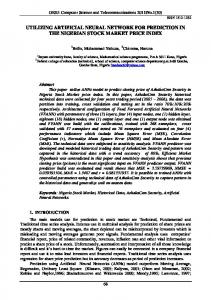
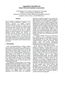
INTRODUCTION Artificial intelligence offers a new dimension in the concept of system automatization. Actual modern engineering implies greater autonomy of the production systems, cars, different machines or robots. Possibility of independently decision-making is greatly emphasized, especially for the cases of a real time unorganized environment and within the conditions with the lack of information or restricted computer equipment. Neural networks are used within engineering activities as prediction tools for different occurrences and parameters, [1-6]. This paper describes the usage of the backpropagation neural network algorithm for the prediction of surface roughness values, based on experimental values of roller burnishing parameters. Roller burnishing of the ship engine component (Crosshead pin), see Figure 1, was conducted within the machining department of the ship engine factory 3. Maj Engines and Cranes.
I. Stanković, Engines & Cranes, Shipyard 3. Maj, Rijeka, Croatia. M. Perinić, Z. Jurković, S. Maričić, Faculty of Engineering, University of Rijeka, Rijeka, Croatia. V. Mandić, Faculty of Mechanical Engineering, University of Kragujevac, Kragujevac, Serbia.
METALURGIJA 51 (2012) 2, 207-210
Four input parameters and one output parameter were measured for different roller burnishing regimes. After 32 different measurements, input and output parameters were processed with the software which developed model of neural network. Developed neural network enabled prediction of the mentioned component surface roughness values for different input roller burnishing parameters, which are controlled by a user.
Figure 1 Component of the ship engine Crosshead pin
207
I. STANKOVIĆ et al.: USAGE OF NEURAL NETWORK FOR THE PREDICTION OF SURFACE ROUGHNESS AFTER... Table 1 Values of the parameters in the realized experiment No.
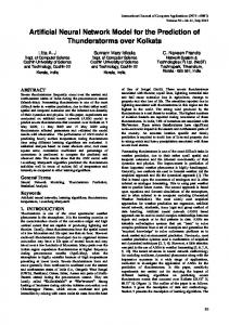
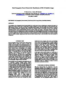
Figure 2 Roller burnishing tool
DEFINITION OF THE PROBLEM AND RESEARCH OBJECTIVE Basic activity of the company 3. Maj Engines & Cranes is a production of the two-stroke low speed ship engines and ship cranes. One of the numerous engine components that are produced inside the factory is the crosshead pin (see Figure 1). Material of the crosshead pin is forged steel (DIN Ck60.6). According to existing process plan, crosshead pins were machined inside factory and then sent to the final grinding (OD mm). Since subcontracting activities induced additional expenses, it was decided to explore the market for alternative solutions. After market investigation, there was found a tool which works on the principle of cold rolling (roller burnishing method). Name of the tool is burnishing roller and it can achieve surface roughness up to Ra=0,08 µm. Figure 2 shows purchased roller burnishing tool. With regard to the fact that roller burnishing toll was never used before, within the 3. Maj Engines and Cranes’ machining department, and since the producer of the tool gave very general working regimes, trial crosshead pin was used in order to test the roller burnishing tool. Parameters which have the most impact on the surface roughness parameter are following, [1]: − Spindle speed, − Burnishing feed rate, − Tool movement towards the workpiece, − Number of tool passes. During the tool testing, four different spindle speeds (50 rpm, 90 rpm, 140 rpm and 180 rpm) and four different burnishing feed rates (0,08 mm/rev, 0,12 mm/rev, 0,16 mm/rev and 0,2 mm/rev) were used. Burnishing force could not be measured since the shortage of measuring tool and due to the unknown tool spring elasticity coefficient. Figure 2 shows that used tool on its end has measuring comparator which measures shortening of the tool spring. It was decided that value which is measured on the comparator will be used in testing purposes instead of burnishing force value. As agreed, the two different tool movements towards the workpiece (0,2 208
Burnishing feed rate / mm/rev 0,08
Tool movement / mm
1
Spindle speed / rpm 50
0,2
Number of tool passes 1
Surface roughness Ra / µm 1,03
2
50
0,08
3
90
0,12
0,2
2
0,42
0,2
3
0,28
4
90
0,12
0,2
4
0,12
5
140
0,16
0,2
5
0,08
6
140
0,12
0,4
1
1,3
7
140
0,12
0,4
2
0,51
8
140
0,16
0,4
3
0,42
9
140
0,16
0,4
4
0,36
10
180
0,2
0,2
5
0,33
11
180
0,2
0,2
6
0,30
12
180
0,16
0,2
7
0,23
13
180
0,16
0,2
8
0,18
14
90
0,2
0,2
1
1,23
15
90
0,16
0,4
2
0,40
16
90
0,16
0,4
3
0,32
17
90
0,16
0,4
4
0,29
18
140
0,08
0,4
5
0,24
19
140
0,08
0,4
6
0,20
20
140
0,08
0,4
7
0,19
21
140
0,08
0,4
8
0,13
22
180
0,2
0,2
1
1,01
23
180
0,2
0,2
2
0,44
24
180
0,2
0,2
3
0,35
25
180
0,2
0,2
4
0,28
26
180
0,2
0,2
5
0,23
27
180
0,2
0,2
6
0,20
28
180
0,16
0,2
7
0,18
29
180
0,16
0,2
8
0,12
30
50
0,12
0,4
1
1,5
31
50
0,16
0,4
2
0,61
32
50
0,16
0,4
3
0,41
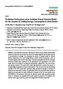
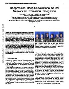
mm and 0,4 mm) were used during the testing. Number of tool passes varied between 1 and 8 passes. During the experiment realization with different working regimes, workpiece surface roughness was measured after each tool pass. Surface roughness parameter Ra was measured with measuring device type TIME Group Inc. TR110. Testing workpiece was machined on the conventional lathe TOS type SU100. Oil emulsion was used for the lubrification of the contact area. Table 1 shows values of measured parameters. Figure 3 shows the roller burnishing tool in action. Figure does not represent tested workpiece. Experimental parameters shown in Table 1 were used for the modeling of the backpropagation neural network for the prediction of surface roughness. Neural network was built through the usage of the computer application EasyNN Plus in a trial version. Application was also used for the presentation of final results. METALURGIJA 51 (2012) 2, 207-210
I. STANKOVIĆ et al.: USAGE OF NEURAL NETWORK FOR THE PREDICTION OF SURFACE ROUGHNESS AFTER...
Figure 3 Roller burnishing tool in action, [7]
DESCRIPTION OF THE NEURAL NETWORK SOFTWARE Computer application named EasyNN Plus 2010 v.14.0d was used as a trial version. Manufacturer of this application is Neural Planner Software. EasyNN Plus grows multi-layer neural networks based on entered input and output parameter values inside of the grid. The neural network input and output layers are created to match the grid input and output columns. Hidden layers connecting to the input and output layers can then be grown to hold the optimum number of nodes. Each node contains a neuron and its connection addresses. The whole process is automatic. The neural networks learn the training data in the grid and they can use the validating data in the grid to self validate at the same time. When training finishes the neural networks can be tested using the querying data in the grid using the interactive query facilities or using querying data in separate files. The steps that are required to produce neural networks are automated in EasyNN-plus, [8].
Figure 4 Grown neural network information data
RESULTS After inserted values, computer application grown neural network with characteristics shown in Figure 4. Figure 4 contains all important information about grown neural network. Neural network was created after 3201 learning cycles. Training error was 0,000753, and validation error was 0,004637. Network had four types of the input parameters and one output parameter. For the training purposes, 26 rows were used from the grid and for the validating purposes six rows. Learning rate was 0,6 and momentum 0,8. Maximum target error was 0,01. Figure 5 shows graphical presentation of grown neural network. Figure 6 shows the curve of the training error propagation. Red line represents maximum training error which in the last cycle had value 0,00509, green line represents average training error which in the last cycle had value 0,000753, and the blue curve represents minimal training error which in the last cycle had value 0. Average validation error is marked with orange curve and in the last cycle had value 0,004637. Deviation of the real surface roughness parameter value (black line) and the one predicted by the grown neural network (red dots) is shown in Figure 7. METALURGIJA 51 (2012) 2, 207-210
Figure 5 Grown neural network configuration
Figure 6 Training error propagation graph
209
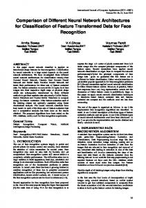
I. STANKOVIĆ et al.: USAGE OF NEURAL NETWORK FOR THE PREDICTION OF SURFACE ROUGHNESS AFTER... Column Input Name 3 1 2 0
Importance Relative Importance
Number of tool passes 40,6619 Burnishing feed rate 11,2645 Tool movement towards... 10,7518 Spindle speed 7,0222
Figure 10 Impact of input parameters on the output surface roughness value
output parameter. Figure 10 shows that the greatest impact on the surface roughness value has the number of tool passes parameter.
CONCLUSION Figure 7 Difference between true and predicted values of surface roughness
Easy NN has the possibility to query predicted values. Query row is inserted in the cells and through the user variation of input parameters, new value of the surface roughness can be calculated. This was the goal of this paper. Query procedure is shown in Figures 8 and 9. Furthermore, Easy NN can calculate which of the multiple input parameters has the greatest impact on the
Usage of the backpropagation neural network for the modeling of the real machining procedure, showed very interesting and valuable results. In fact, computer modeling of the actual roller burnishing procedure through the usage of the neural network, enabled to a user possibility to determine the values of the roller burnishing parameters for wanted surface roughness. Developed computer model can give quick and cheap answers needed for construction of the process plan. It is shown that developed model can predict values of machining parameters with the average mistake lower than 1 %. This mistake confirms the value of the developed neural network model and justifies the usage of such a model in practical work. Grown neural network can be used as described in this paper, or it can be integrated inside the ERP system.
REFERENCES [1]
[2]
Figure 8 Predicted value of surface roughness on the right side for shown input parameters values on the left side
[3]
[4] [5]
[6]
[7] [8]
Figure 9 Increased value of surface roughness due to decreased spindle speed and decreased number of tool passes
210
El Axir, M.H.: An Investigation Into Roller Burnishing, International Journal of Machine Tools & Manufacture, 40 (2000), 1603-1617. Novakovic, B., Majetic, D., Siroki, M.: Umjetne neuronske mreze, Faculty of Mechanical Engineering and Naval Architecture, University of Zagreb, Zagreb, 1998. Dalbelo-Basic, B., Cupis, N., Snajder, J.: Umjetne neuronske mreze, Faculty of Electrical Engineering and Computing, University of Zagreb, Zagreb, 2008. Rojas, R.: Neural Networks: A Systematic Introduction, Springer, Berlin, 1996. Bulic, N.: Upravljanje sustavom uzbude sinkronog generator upotrebom neuronske mreze, Faculty of Electrical Engineering and Computing, University of Zagreb, Zagreb, 2005. Simunovic, G., Saric, T., Lujic, R.: Primjena neuronskih mreza u procjenjivanju kvalitete obradivane povrsine, Tehnicki vjesnik, 16, 2(2009), 43-47. Roller Burnishing Tools, Mech-India, katalog alata, India, 2009. EasyNN Plus Help, Tutorial, 2010.
Note: The responsible translator for English language is Ksenija Mance, a Senior Lecturer at the Faculty of Engineering, University of Rijeka, Croatia.
METALURGIJA 51 (2012) 2, 207-210