Smelter Gas Control Overview
Using Computational Fluid Dynamics to Modify a Waste-Heat Boiler Design Yongxiang Yang, Ari Jokilaakso, Pekka Taskinen, and Markku Kytö
This article describes the use of a generalpurpose computational-fluid-dynamics code for improving and optimizing waste-heat boilers in the Outokumpu flash smelting process. The codes offer opportunities to study the transport phenomena for fluid and particulate flow and heat and mass transfer. The simulation includes gas- and dust-flow behaviors and gas cooling by convection and radiation. The results were used in the boiler modification for increased capacity and higher cooling efficiency. The modified boiler, with its unique design, has been in use at Outokumpu’s Harjavalta copper smelter since June 1995 with excellent performance.
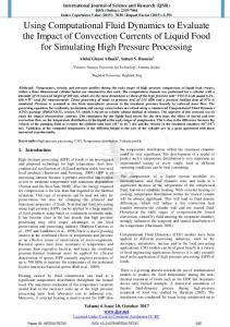
aerodynamic design of the waste-heat boiler Radiation Screens with maximum cooling efficiency, minimized dust build-ups, and fouling is essential for operation. For an optimal boiler design, an analysis of fluid flow and heat transfer is required. Physical Figure 2. The flow pattern of the unmodified waste-heat boiler water and gas models are under the basic operating conditions. useful in providing flow features of the boiler; however, physical conducted in parallel with the physical modeling of the flow and heat transfer modeling and boiler redesign. under non-isothermal conditions is difINTRODUCTION THE WASTE-HEAT BOILERS ficult to carry out. The adoption of computational fluid dynamics (CFD) codes Sulfide-smelting processes generate All of the Outokumpu-type flash for modeling smelting, refining, and castlarge volumes of hot, dust-laden off-gas, smelters are equipped with a horizontal ing operations has increased greatly in which must be treated for energy recovwaste-heat boiler consisting of a radiarecent years.5,6 CFD modeling, in combiery and hygiene and environmental retion section and a convection section. In quirement adherence. In the Outokumpu the radiation section, hot gases and molnation with physical models and indusflash smelting process for the producten dust are cooled rapidly in a large trial measurements, is very effective for tion of primary copper and nickel,1 the space. The convection section is smaller, this purpose, although little on the CFD with a shape similar to the radiation modeling of waste-heat boilers has been use of waste-heat boilers is standard section. In the upper part, a number of found in the literature.7 practice.2–4 However, they often slow convection tube-banks are introduced down the continuous operation of the In 1995, Outokumpu completed exin order to efficiently extract the heat. smelter, due to insufficient cooling, dust pansion at the Harjavalta copper smelter The dust on the tube surfaces is removed build-ups, and surface fouling. Proper to increase the anode copper production periodically with spring hammers and from 100,000 t/y to placed on a conveyor to be recycled to 160,000 t/y. The off-gas the smelting furnace. volume from the furnace The boiler membrane walls, the radiawas increased from tion screens, and the convection tube19,000 Nm3/h to 37,000 banks are cooled by forced circulating Nm3/h. The waste-heat water-steam mixture at high pressure. boiler was not able to cool The thermal energy is recovered as satuthe new off-gas volume, rated or superheated steam at high presand a modification was sure and used for power generation. required. Waste-heat boilers, which are installed Since 1993, physical in line with the flash-smelting furnace at modeling with laboraa Outokumpu, cool the off-gas from tory-scale models was 1,200~1,350°C to about 350°C for the conducted at the Outoelectrostatic precipitator (ESP). Roughly kumpu Research Center two-thirds of the dust is settled in the to visualize the flow patwaste-heat boiler.9 tern of different geometric arrangements.8 HowThe boiler before modification had a ever, whether the new flat roof across the radiation and convecboiler design is able to tion sections (Figure 1a). The off-gas temsufficiently cool the offperature was 1,300–1,350°C, and the comgas with an increased position was characterized by an SO2 flow rate and higher temcontent of about 30 percent. Part of the perature cannot be anoff-gases at about 200°C was circulated swered by scale modelfrom the ESP to the radiation section to b ing. Therefore, the CFD cool the hot off-gas more rapidly and to Figure 1. Schematics of the waste-heat boiler of Outokumpu simulation of gas flow assist dust sulfating. The off-gas conHarjavalta Metals copper smelter (a) before May 1995 and (b) and heat transfer was tained 150–220 g/Nm3 molten or semiafter June 1995. 36
JOM • May 1999
molten dust, most of which was fully oxidized. Upon cooling in the radiation section, oxide dust was mostly sulfated at 500–800°C. Due to a slight underpressure and dust-unloading operation, some ambient air was leaked into the boiler from the dust hoppers. In order to increase the cooling capacity, the boiler was modified as described elsewhere (Figure 1b).10 The roof of the radiation section is lifted near the inlet, and there is a cooling dam (a baffle channel) in the middle. Four groups of radiation screens are installed to provide more heat-transfer surfaces. The convection section has two additional tube-banks. Between 3,000 Nm3/h and 10,000 Nm3/ h circulated off-gas from the ESP at 300°C is used as optional operation practice. Various arrangements were considered, and the final proposal was a single feeding slot at the centerline, 55° downward. The leakage air from dust hoppers was estimated to be about 3,000 Nm3/h in the radiation section. The dust loading in the off-gas is similar to the figure before modification, and the SO2 content is slightly higher. GAS-FLOW PATTERN ANALYSIS Gas flow in the boiler is three-dimensional. The CFD simulation gives detailed information of the gas flow within its whole volume. As found in physical models in the laboratory, the flow has a recirculating nature, especially in the radiation section. The circulated off-gas was found to affect the flow pattern significantly. Flow Pattern Before Modification Figure 2 illustrates the computed gasflow pattern in the unmodified boiler. The gas velocity near the ceiling is high
Dam
a
Dam
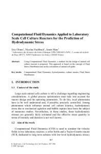
b Figure 3. General gas flow pattern in the final design of the modified boiler (a) without circulated off-gas and (b) with circulated off-gas.
1999 May • JOM
and generally up-forward. A recirculating backward flow prevails in the middle and lower regions of the radiation section. The flow inside the upper convection section is basically horizontal and rather uniform. With CFD simulation, non-isothermal mixing of gas streams can be studied, which are difficult to simulate with physical models. The effects of the circulated off-gas and leakage air from dust hoppers on the flow pattern and their mixing behaviors were studied in detail. The results show that the circulating off-gas significantly affects the gas-flow pattern, especially with asymmetric feeding. The results indicate that the gas flow in the unmodified boiler has a less preferred pattern, which confirms previous industrial experience and physical model observations. There is a short circuit in the radiation section. A large portion of the boiler space in the lower part of the radiation section is not utilized efficiently for cooling the gas. The numerical tracer experiments by CFD for residence time distribution (RTD) show a dead volume in the radiation section as high as 38%. Flow Pattern After Modification In the boiler modification, the focus was to improve the general gas-flow pattern and reduce the gas short circuit and dead volume in the radiation section in order to provide more efficient gas cooling. A lot of physical model experiments were conducted, and the preferred geometric configurations were screened for detailed numerical simulation. Two versions were proposed: three dust hoppers with sharp corners and two dust hoppers with smooth corners in the radiation section. The results show that both configurations result in an improved gas-flow pattern without the offgas circulation, with much reduced recirculation and dead volume. The gas short circuit is eliminated. A separate boiler model without the furnace uptake gives the opportunity to study the effect of the gas-incoming angle. The results confirmed that the incoming angle has a significant effect on the flow pattern before the dam. Figure 3 illustrates the gas-flow pattern at the symmetric central plane with and without circulated off-gas. Without circulated off-gas, a larger recirculating zone forms above the boiler inlet before the dam. When the off-gas circulation is used, the recirculation zone is significantly reduced. Simulation of the off-gas circulation showed that its vertical feeding from a single and double slot yields a localized and limited mixing effect as compared to the inclined feeding. The gas mixing in inclined feeding spreads almost in the whole region before the dam. In addition to the velocity distributions, a thorough analysis of the mass-fraction dis-
a
Dam
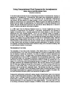
b Figure 4. A comparison of (a) a 3-D gas model and (b) the computed flow field at the symmetric centerline for the industrial modified boiler (radiation section). The darker areas in the 3D gas model are the smoke tracers.
tribution was carried out when the circulated off-gas and air leakage were included. Flow Characterization by RTD Analysis An analysis of the RTD in both boilers was carried out with numerical-tracer experiments. Tracers were virtually added to the inlet by both step- and jump-input methods to a solved nonisothermal gas-flow model. Thus, both the integral F-curve and differential Ecurve of the tracer distribution at the outlet are obtained. The distribution curves for the radiation section of the boiler before and after the modification without circulated off-gas show that the flow is back mixing. Part of the gas is in the stagnant region—the dead volume. Thus, the boiler both before and after modification can be characterized as a combination of back mixing with dead volumes. Analysis of the mean residence time, dead volume, and backmixing region indicates that the modification significantly reduced the dead volume from about 38% to 15% in the radiation section. The utilization of the space in the modified boiler is much higher than in the unmodified boiler. The reduction in short circuit is significant. The off-gas circulation in the final design almost eliminates the dead volume. A Comparison of Numerical Models and Physical Models For the unmodified boiler, computational results of the full-scale industrial boiler were qualitatively compared with
37
NUMERICAL-SIMULATION TOOLS
Gas Cooling Before Modification
The unmodified boiler provided a good source of data for the heat-transfer modeling. For appropriate adjustment of the absorption coefficient, validating models of the unmodified boiler were created for the operating conditions where measured data were available. The conditions simulated were use of the circulated off-gas (symmetric and asymmetric), sensitivity to the wall temperatures, and sensitivity to the absorption coefficient of the media. The heat-transfer simulation showed that the TEMC hot off-gas stream cools 34 129 down rapidly from 225 320 1,350°C to about 1,000°C 415 after entering the radia511 606 tion section. In contrast, 702 797 the temperature distribu893 988 tion in the lower part of 1084 1179 the radiation section is 1275 quite uniform. The com1370 puted outlet temperature a from the radiation section is around 800°C. The predicted outlet temTEMC perature from the con28 vection section is about 124 220 400°C. 316 412 Computed tempera507 603 ture distribution with the 699 measured data16 has been 795 891 analyzed at a plane be987 1002 tween the centerline and 1178 1274 the sidewall and the tem1370 perature profile crossing the upper four measurb ing points for validating Figure 5. Temperature distribution in the boiler after the modithe model, under similar fication at (a) 610–735°C outlet, Tave = 655°C and (b) 614– operating conditions 660°C outlet and Tave = 624°C. Heat transfer in the waste-heat boiler is very complicated. The high-temperature off-gas contains large amounts of emitting and absorbing SO2 , and the molten or solid dust is an emitting, absorbing, and scattering medium. The tube-banks in the convection section contain about 1,000 heat exchange tubes, which are difficult to describe in computation.
38
where the off-gas circulation was not used. The calculated temperature agrees well with measured data, and the trend of the temperature distribution is well predicted. The rapid cooling near the boiler inlet by thermal radiation is confirmed. Gas Cooling After Modification Gas cooling and heat transfer in various operating conditions was simulated. Emphasis was put on the temperature distribution, overall gas cooling, and heat-flux analysis in the radiation section. A detailed heat-transfer simulation was conducted for both an intermediate and the final geometry. For the final design, a parametric study was conducted, including process gas-flow rate and its incoming angle. Figure 5 illustrates the temperature distribution contours with and without circulated off-gas. The results indicate that after entering the boiler the gas cools rapidly in the first half of the radiation section. An impinging hot stream to the dam front can be noticed. The average outlet temperature from the radiation section is 655°C. When the circulated off-gas was added, the characteristics of the temperature distribution change significantly. The hot stream impinging to the dam-front surface was eliminated. More uniform temperature distribution is obtained due to the dispersion effect of the circulated off-gas. On the average, 700 °C)
GAS-COOLING ANALYSIS
The radiative heat transfer in the radiation section was the main focus of study. A detailed heat-transfer simulation of the convection section is a formidable task to accomplish; however, the convective heat transfer in the convection section of the unmodified boiler was also studied by simplified approaches with groups of plates of the same total surface area as the tube-banks and the estimated convective heat-transfer coefficients.
efficiency can be evaluated. In addition, the approach of the Lagrangian particle tracking was tested to get particle tracks and histories. The gas properties were estimated from the composition as a function of temperature, and a critical evaluation of the emissivity of the gas-particulate mixture was conducted, due to its strong correlation with the radiative heat transfer. For SO2-rich off-gases, little could be found in the literature, and a careful validation of the predicted temperature distribution by measured data is important. For dust-sulfating reactions, the reaction heat was estimated thermodynamically and included as a macroscopic energy source in the radiation section. More information can be found in References 14 and 15.
600● ●
● ● ● ● ●
500 T(
2-D water and 3-D gas models. In addition, the videotaped gas model was also used for comparison. For the modified boiler, the computed flow pattern of the full-scale industrial boiler was compared with a laboratory-scale gas model. Figure 4 illustrates the flow field of a 3-D gas model and the computed velocity vectors in the central plane of the industrialscale modified boiler. The tools give similar results, and the computed main flow features agree well with the observations in the physical model.
accuracy. Tests of two other k-ε based turbulence models (RNG12 and Chen-Kim13) showed minor differences in the general flow pattern as compared to the standard k-ε model. For thermal radiation, a compositeflux model was used. Different grids were tested to check the grid independence of the simulation results. For the best convergence and to meet the requirements of the radiation model, Cartesian grids with a variety of cell numbers were utilized in different stages of simulation. To study the dust-flow behavior, the Eulerian-Eulerian two-fluid approach was used, which assumes both the particles and gases are interpenetrating phases. In transient cases, the dust accumulation and capture
1
2
3
4
5
●
● ● ● ● ● Measured ● 3
Measurement Chronological Order: 2, 3, 4, 5, . . . 12, 13, 1
400
30,000 Nm /h 25,000 Nm3/h
6 7 8 9 10 11 12 13 Location Point
600
T (°C)
The gas flow in industrial waste-heat boilers is turbulent. The transport processes in a boiler can be described with time-averaged Navier-Stokes equations for mass continuity and momentum conservation and additional partial-differential equations for conserving energy and the chemical species. In this work, the governing transport equations were solved numerically with the general-purpose CFD package Phoenics,11 based on the finite-volume approach, by supplying all initial and boundary conditions. Phoenics provides a variety of turbulence and thermal-radiation models. In this study, the standard k-ε model was used in most cases for gas-phase turbulence due to its robustness, generality, and reasonable
500
400
On-Line Temperature Measurement in the End of the Radiation Section (Manual-Copy)
20
40
60 80 100 Time (Minute)
120
140
Figure 6. A comparison of temperature measurements with the computed results.
JOM • May 1999
Figure 7. A 2-D view of particle tracks (50 µm) in the modified boiler.
the gas is cooled to 624°C in the outlet, and further gas cooling by the circulated off-gas is about 30°C. The temperature gradient in the outlet of the radiation section is also significantly reduced by a better gas-mixing pattern due to the circulated off-gas. The effect of gas-flow rate in the range of 20,000–60,000 Nm3 /h on the cooling capacity was studied to obtain an indication of how much the gas may be cooled. The computed results show that the boiler can cool the gas to about 750°C in the radiation section even at a gas-flow rate of 60,000 Nm3/h. At 20,000 Nm3/h, the gas will be cooled to about 550°C. Radiation was confirmed to be the main heat-transfer mode in the radiation section, accounting for 65–80% of the total heat transferred for the modified boiler under different conditions studied. The results indicate that increasing the gas-flow rate from 20,000 Nm3/ h to 60,000 Nm3/h in the modified boiler will lower the radiation share by 10%. Applying the circulated off-gas up to 10,000 Nm3/h lowers the share of radiation by 15% at the process gas-flow rate of 37,000 Nm3/h. The total heat transferred through boiler walls is important, and the heatflux distribution to different walls is essential to operation. The simulation showed that the four radiation screens have a total contribution of 40–43% to the total heat transfer. The calculated heat fluxes in the modified boiler were the highest to the walls around the inlet (~45 kW/m2) and slightly lower on the first radiation screen group and the damfront surface (~40 kW/m2). The heat fluxes to other surfaces are much lower, 10 W/m2 –20 W/m2. Temperature Measurements in the Modified Boiler Temperature measurements were conducted in order to validate the heattransfer models. The boiler operated during the measurement period at a gasflow rate of 25,000–30,000 Nm3/h and a smelting capacity of 80–100 t/h feed mixture. To assist dust sulfating, 3,000 Nm3/h ambient air was supplied to the uptake shaft. Thirteen measurements were done from behind the cooling dam. Two validating models were set up at gas-flow rates of 25,000 Nm3 /h 1999 May • JOM
and 30,000 Nm3 /h. Figure 6 shows a temperature comparison with the computed temperature profile at the same locations. The graph also includes the temperatures recorded at the end of the radiation section to show a process disturbance during the measurements. The large discrepancy in points 6–10 was caused by a lower feed rate. Taking this into account, the agreement between the measurements and computation is good, and the deviation is in the range of 10– 50°C. The temperature trend along the measurement line is well predicted. DUST FLOW AND SETTLING ANALYSIS The flue-dust carried by the off-gas may cause various operational problems, such as build-ups and fouling, corrosion, and erosion to the heat-transfer surfaces. These problems may require frequent dust removal and surface cleaning, all of which may result in the interruption of furnace operation. The flow and dust-settling behavior in the radiation section of the modified boiler was studied for a wide range of particle sizes. The total dust captured in the radiation section of the boiler (including the uptake shaft and part of the convection section) in terms of the dustcollecting efficiency was obtained from the transient simulation. The dust loading is 200 g/Nm3 from the smelting furnace off-gas, with particle sizes 1–100 µm. The dust particles are assumed to be spherical in the solid state. The density of the particle is estimated as 3,000 kg/m3. Dust volume fraction at the model inlet was estimated as 1.2 × 10⁻⁵ . Steady-State Simulation In the steady-state simulation, dust behavior with both isothermal and nonisothermal gas flow was studied, including the effects of off-gas circulation from ESP and air leakage. In the non-isothermal simulation, a solved temperature field of the gas phase was fixed to a twophase simulation. Simulation showed that particles below 20 µm do not tend to settle appreciably in the boiler, and particles larger than 20 µm tend to accumulate significantly in the first dust hopper of the radiation section and slightly in the convection-section hopper. For non-isothermal gas flow, the dustvolume fraction in the dust hoppers is about 10–20 times higher than in the isothermal cases, where no off-gas circulation is involved. Due to a drop in gas velocity from cooling, the dust particles will lose their momentum more quickly and settle early into the lower part of the boiler. Adding the circulation off-gas from ESP will increase the velocity difference between the gas and particle phases.
More dust accumulation takes place in the convection-section hopper, caused by the stream of circulating off-gas and leakage air. The simulation showed that small particles below 50 µm could not settle appreciably in the radiation section. However, for larger particles of 75 µm, the accumulation takes place significantly within the dust hoppers in the radiation sections. Transient Simulation and Dust-Capture Efficiency In the transient simulation, the dust particles were added from the middle of the furnace settler (the inlet of the model) to a steady gas-flow system. The dust particles are carried by the off-gas along the furnace uptake and the boiler radiation section. In a steady-state flow, the fraction of the dust out of the boiler outlet will not change, and a constant fraction of the dust is flowing through the radiation section of the boiler; the rest settles down in the boiler. A great benefit of the transient study with the two-fluid approach was the avoidance of the steady-state restraint by which the incoming and outgoing mass flow rate must be equal, so that the settling fraction of the dust can be obtained. In addition, the change of dust volume fraction in the boiler can be tracked with time. The numerical results indicate that in the steady state, 60–70% of the dust particles coming from the smelting furnace leaves the outlet of the radiation section of the boiler for all the particle sizes studied. Therefore, it may be estimated that the fraction of the dust settled within the boiler radiation section (dust-collecting efficiency) falls in the range of 30–40%. Particle Tracking As another approach for treating multiphase flow, the Lagrangian particle tracking approach was also tested in order to get the particle tracks and history. Figure 7 illustrates how 50 µm particles (bouncing at walls) injected at 20 locations crossing the settler flow in the uptake shaft and the radiation section of the modified boiler. An analysis of particle residence time for individual particle parcels (50 µm) indicates that some particles go out of the radiation section in about ten seconds, and some particles take about 40 seconds to go through the settler/uptake and radiation-chamber combination. The particle tracks closely follow the gas flow. In the future, the sticking behavior of molten particles will be studied, which is important for the dust fouling. CONCLUSIONS Based on the simulation results, the following conclusions were made for (Continued on page 47.) 39
Yang (Continued from page 39.) the modified boiler. First, it has a very high cooling capacity, and the radiation section cools the gas to 750°C even at a flow rate of 60,000 Nm3/h. Second, the cooling dam efficiently reduces the dead volume of the radiation section. Third, the radiation screens contribute 40–43% to the total heat transfer, while radiation heat transfer accounts for 65–80% of the total heat transferred. Fourth, flue dust below 20 µm closely follows the gas flow and does not settle appreciably in the boiler. Finally, the dust-collecting efficiency in the radiation section is about 40% for large particles of 75–100 µm and roughly 30% for smaller particles of 25–50 µm. ACKNOWLEDGEMENTS The authors thank the Ministry of Trade and Industry and the Technology Development Center (Tekes) of Finland for financing the work. Thanks are also due to T. Mäntymäki, vice president of Outokumpu Harjavalta Metals Oy, for permission to publish the data on the waste-heat boilers, for arranging temperature measurements, and for his interest in this work. K. Rajainmäki of Outokumpu Research Oy, for conducting
the temperature measurements, and the support of the copper smelter are very much appreciated. References 1. R.J.M. Wylle, “Flash Smelting at 40,” E&MJ (October 1989), pp. 22–27. 2. K. Kaasila and E. Löytymäki, “Heat Recovery in Metallurgical Processes and Applications within Outokumpu Company,” Advances in Extractive Metallurgy and Refining, ed. M.J. Jones (London: IMM, 1972), pp. 591–603. 3. B.T. Andersson and A.P. Päärni, “Optimization of Flash Smelter Off-Gas Cooling and Cleaning,” Advances in Sulfide Smelting, ed. H.Y. Sohn et al. (Warrendale, PA: TMS, 1983), pp. 1003–1022. 4. P. Hanniala and I. Kojo, “Utilization of Outokumpu Flash Technology to Meet Environmental Requirements,” Proceedings of COPPER 95 International Conference, Vol. II—Mineral Processing and Environment. ed. A. Casali et al. (Montreal, Canada: Metallurgical Society of CIM, 1995), pp. 305–318. 5. J. Szekely, “Mass Transfer, Heat Transfer and Computational Fluid Dynamics in Process Metallurgy,” Proceedings of the Elliott Symposium on Chemical Process Metallurgy (Warrendale PA: ISS, 1990), pp. 447–462. 6. M.P. Schwarz, “Flow Simulation in Mineral Engineering,” Minerals Engineering, 7-11 (4) (1991), pp. 717–732. 7. H. Holopainen et al., “Latest Developments in Gas Cooling in Copper Smelters,” Proceedings of Copper 95 International Conference, Volume IV—Pyrometallurgy of Copper, ed. W.J. Chen et al. (Montreal, Canada: Metallurgical Society of CIM, 1995), pp. 313–332. 8. Lilja and Rajainmäki, “On the Experimental and Computational Modeling at Outokumpu Research Oy,” The 2nd Colloquium on Process Simulation, ed. A. Jokilaakso (Espoo, Finland: Helsinki University of Technology, 1995), pp. 217– 230. 9. A.K. Biswas and W.G. Davenport, Extractive Metallurgy of Copper, 3rd edition (Oxford, U.K.: Pergamon, 1994), pp. 277– 303. 10. L. Lilja et al., “Method and Apparatus for Increasing the Efficiency of a Waste Heat Boiler,” U.S. patent 5,431,373 (July 11, 1995).
11. H.I. Rosten, D.B. Spalding, and D.G. Tatchell, “Phoenics: A General-Purpose Program for Fluid-Flow, Heat-Transfer and Chemical-Reaction Processes,” Proceedings of the 3rd International Conference on Engineering Software (London: Imperial College, 1983), pp. 639–655. 12. Y.S. Chen and S.W. Kim, “Computation of Turbulent Flows Using an Extended k-ε Turbulence Closure Model,” NASA Report CR-179204 (1987). 13. V. Yakhot et al., “Development of Turbulence Models for Shear Flows by a Double Expansion Technique,” Phys. Fluids A, 7 (4) (1992), pp. 1510–1520. 14. Y. Yang, “Computer Simulation of Gas Flow and Heat Transfer in Waste-Heat Boilers of the Outokumpu Copper Flash Smelting Process,” Acta Polytechnica Scandinavica, Chemical Technology Series No.242 (Helsinki, Finland: Finnish Academy of Technology, 1996). 15. Y. Yang et al., “Gas Flow and Cooling in Waste-Heat Boilers in the Outokumpu Flash Smelting Process,” Sulfide Smelting ’98: Current and Future Practices, ed. J.A. Asteljoki and R.L. Stephens (Warrendale, PA: TMS 1998), pp. 417–431. 16. R. Backman, M. Hupa, and J.K. Mäkinen, “Formation and Corrosion Effects of Sulphur Trioxide in Copper Smelting Processes,” TMS Technical Paper No. A86-56 (Warrendale, PA: TMS, 1986).
Yongxiang Yang is a university docent at Delft University of Technology, Netherlands. Ari Jokilaakso is an R&D metallurgist at Outokumpu Engineering Contractors Oy, Finland, and a docent at Helsinki University of Technology. Pekka Taskinen is the vice president of pyrometallurgy at Outokumpu Research Oy, Finland, and a docent at Helsinki University of Technology and at the Faculty of Technology, University of Oulu, Finland. Markku Kytö is the vice president of technology at Outokumpu Technology Oy, Finland. For more information, contact Y. Yang, Delft University of Technology, Raw Materials Technology/Applied Earth Sciences, Mijnbouwstraat 120, Delft, 2628 RX, Netherlands; telephone 3115-278-2542; fax 31-15-278-2836; e-mail
[email protected].