In this paper, the gain of deploying dedicated in-building systems in terms of HSDPA indoor coverage and capacity is studied; first, with a simple analytical ...
Using Dedicated In-Building Systems to Improve HSDPA Indoor Coverage and Capacity Kimmo Hiltunen1, Birgitta Olin2, Magnus Lundevall2 1
Ericsson Research, Oy LM Ericsson Ab, FI-02420 Jorvas, Finland, tel. +358 9 2993309, fax +358 9 2993535 2 Ericsson Research, Ericsson AB, SE-16480 Stockholm, Sweden {Kimmo.Hiltunen, Birgitta.Olin, Magnus.Lundevall}@ericsson.com
Abstract—In WCDMA systems, in particular with the introduction of high-speed multimedia services, the demand for good indoor coverage will become important. Overlaying macro cells can provide a sufficient level of general indoor coverage for most of the cases. However, in order to be able to provide WCDMA indoor coverage and capacity within traffic hot spots, such as airports, shopping malls and large office buildings, the deployment of dedicated in-building systems may be required. In this paper, the gain of deploying dedicated in-building systems in terms of HSDPA indoor coverage and capacity is studied; first, with a simple analytical reasoning and after that, with advanced system simulations. The results show that the HSDPA performance can be improved considerably within the indoor hotspot area by deploying a dedicated in-building system. The results also demonstrate how a dedicated in-building system can off-load the overlaying macro cell, and as a result of that, improve the grade of service considerably for the co-existing nonHSDPA users. Keywords-WCDMA, HSDPA, in-building systems, coverage, capacity
I. INTRODUCTION In the initial roll-out of WCDMA networks, macro base stations have typically been deployed to cover both outdoor and indoor areas. The networks are planned to support indoor traffic but there might be indoor areas with poor coverage. In such situation a dedicated in-building system can be a solution to the problem. Moreover, even in areas with sufficient coverage from the macro base stations, dedicated in-building systems can be used to off-load the macro network. Furthermore, with the introduction of high-speed multimedia services, and e.g. the High-Speed Downlink Packet Access (HSDPA) technology [1], the demand for good indoor coverage will become even more important. The impact of deploying dedicated in-building systems has been studied for example in [2] and [3]. Furthermore, in [4], the impact of indoor traffic on macro cell uplink and downlink capacity has been discussed. In this paper, two means to serve an indoor traffic hot spot are compared; outdoor-to-indoor coverage, and through a dedicated in-building system. Both the HSDPA performance inside the building and the speech
0-7803-8887-9/05/$20.00 (c)2005 IEEE
capacity in surrounding macro cells are evaluated. The HSDPA performance is discussed based on the downlink carrier-tointerference ratio equation and numerical results are obtained through dynamic system simulations including detailed propagation models. The rest of this paper is organized as follows. First, in Chapter II the impact of deploying dedicated in-building systems is discussed based on analytical reasoning. Then, in Chapter III, the assumed system scenario and the most important simulator models are introduced. The system simulation results are presented in Chapter IV. Finally, some conclusions are drawn in Chapter V. II. ANALYTICAL REASONING Based on analytical reasoning, using the WCDMA downlink carrier-to-interference ratio as a starting point, this chapter discusses how the HSDPA performance is affected by the different deployment options. A. General Due to the link adaptation functionality, the HSDPA bit rate for a certain user k served by a base station j is an increasing function of the downlink Carrier-to-Interference Ratio [1, 5], γk,j, defined as
γ k, j =
PHS , k , j ⋅ G k , j
,
(1)
B
α k , j ⋅ Ptot , j ⋅ G k , j + ∑ Ptot , i ⋅ G k , i + N k i =1 i≠ j
where PHS,k,j is the transmit power on High-Speed Downlink Shared Channel (HS-DSCH), Gk,j is the path gain towards the serving base station, αk,j is the non-orthogonality factor, Ptot,j is the total base station output power, B is the total number of base stations, and Nk is the mobile receiver noise power. Now, let PHS,k,j be a fraction βk,j of the maximum base station output power, Pmax. Furthermore, for simplicity, let Ptot,j = Pmax and Ptot,i = Ptot ≤ Pmax ∀ i. Thus,
Downlink inter−to−intracell interference ratio 1
1 Outdoor−to−indoor Dedicated in−building
0.9
0.8
0.8
0.7
0.7
0.6
0.6 CDF
CDF
0.9
0.5
0.4
0.3
0.3
0.2
0.2
0.1
0.1
−6
−4
10
−2
10
0
10
10
0 0
2
10
F
k,j
Figure 1. A rough estimate of the distribution of Fk,j values for the outdoorto-indoor and the dedicated in-building scenarios.
β k, j
γ k, j = α k, j +
Ptot ⋅ Fk , j Pmax
,
(2)
Nk + Pmax ⋅ G k , j
B
∑G Fk , j =
k ,i
i =1 i≠ j
Gk, j
(3)
B. HSDPA Outdoor-to-Indoor Coverage and Capacity For a HSDPA user sharing the macro cell capacity with non-HSDPA users having higher priority, e.g. speech, the value of βk,j will become lower than in case of a “pure” HSDPA cell. The higher the level of co-existing traffic, the smaller the value of βk,j. Looking at (2), it is obvious that a smaller βk,j results in a smaller γk,j, and thus, a lower user bit rate. Furthermore, for a user k inside a building, a simple assumption could be that the building penetration loss Lk is the same towards all surrounding macro base stations. Thus, the value of Fk,j would not depend on Lk. However, the value of Gk,j is reduced by Lk resulting in lower γk,j values, and consequently, lower user bit rates. The lower user bit rates can be motivated further by the fact that as a result of the reduced Gk,j the required Associated Dedicated Physical Channel (A-DPCH) transmit power is increased, resulting in smaller βk,j for the HS-DSCH. From the HSDPA cell capacity point of view, the key issue is the distribution of γk,j values over the cell coverage area. Since the HS-DSCH is a shared channel, a scheduling function is needed to decide which HSDPA user is allowed to transmit on HS-DSCH. As mentioned, the bit rate of a certain HSDPA user k depends on the carrier-to-interference ratio γk,j and the HSDPA cell throughput depends on the bit rates of the scheduled users.
Dedicated In−Building System
0.5
0.4
0 −8 10
Outdoor−to−Indoor Coverage
Top Floor
0.5
1
1.5
γ/β
2
2.5
3
3.5
Figure 2. A rough estimate of the distribution of γk,j/βk,j values for the outdoor-to-indoor and the dedicated in-building scenarios. Solid lines represent the results per floor, while the dashed lines are representing the distribution over the entire building.
C. HSDPA Indoor Coverage and Capacity with a Dedicated In-Building System When a dedicated in-building system is deployed to serve the indoor traffic, the HSDPA performance is expected to improve. There are a few main reasons for this: •
For a user inside the building, the path gain towards the in-building base station is usually much larger than the path gain towards the closest macro base station, which not only reduces the impact of receiver noise on γk,j, but also results in smaller Fk,j. As a result, γk,j will improve, and consequently the HSDPA bit rate.
•
The value of the non-orthogonality factor αk,j depends on the multipath channel profile experienced by a user k: the wider the delay spread, the larger the αk,j. Looking at (2) it is obvious that a larger αk,j will result in a lower γk,j, and thus, a lower user bit rate. Typically, a user connected to a macro base station will experience a multipath channel with a wider delay spread compared to a user connected to an inbuilding system.
•
Assuming that the building will contain only a few high priority users, a larger fraction of the base station power can be allocated to HS-DSCH. Thus, βk,j will become larger, resulting in an improved γk,j, and a higher user bit rate.
•
Looking at the building as a whole, the distribution of Gk,j values will become more favorable, αk,j and Fk,j values will become smaller, and larger βk,j can be allowed compared to the scenario, where HSDPA users are covered with the macro cell. As a result, the γk,j distribution will improve, and thus, the overall HSDPA cell capacity will become larger.
The effects of the first and last bullets can be observed by looking at the path loss distributions within the assumed
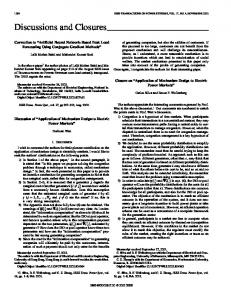
500 400 300 200
[m]
100 0 −100 −200 −300 −400 −500
0
200
400 [m]
600
800
1000
RBS
Figure 3. Location and size of the modeled building.
Figure 4. Structure of the assumed in-building system.
deployment scenario, which is described in more detail in Chapter III. By using the information about the path losses between the base stations and the HSDPA users, the distributions of Fk,j and γk,j/βk,j can be obtained, see Figure 1 and Figure 2, respectively. In Figure 2, it has been assumed that Ptot = 0.5⋅Pmax and Nk = -99 dBm. Furthermore, for the outdoor-to-indoor scenario αk,j is assumed to be equal to 0.66, while for the dedicated in-building system αk,j = 0.32 for all users. The above αk,j values are valid for a traditional RAKE receiver. By using a G-RAKE receiver [6] part of the intracell interference could be suppressed, resulting in a smaller αk,j, and thus, better HSDPA performance.
The modeled building is located in one of the macro cells, as shown in Figure 3. The building consists of six identical floors with an area of 80 m * 80 m. The height of each floor is 3.5 m. The path loss values between the macro sites and the mobiles are calculated using the COST 231 – WalfischIkegami model [7]. On top of that, for mobiles located inside the modeled building, the additional building penetration loss including the floor height gain is calculated using the non-lineof-sight model as defined in [7].
As can be seen, the Fk,j values are considerably reduced as a result of the dedicated in-building system. Even if the possible increase in βk,j is ignored, the CIR values become considerably larger. As can be expected, CIR is improved the most on the lower floors, which are also the most difficult to cover with macro cells. For example, for the worst 10th percentile of the users on the ground floor, CIR is improved by 15 dB. The gain in CIR is reduced the higher up in the building the user is located. The reason for this is two-fold: firstly, the users on the upper floors have already a fairly good macro cell coverage to start with. Secondly, the interference from macro cells, i.e. the level of the intercell interference is also higher on the upper floors compared to the lower floors. Hence, for the users on the upper floors, the gain in CIR is mainly caused by the improved downlink orthogonality. As a result of this uneven improvement in bit rates on the different floors, the dedicated in-building system results in fairly similar user performance throughout the building. III. SYSTEM MODEL In this paper, the analytical reasoning presented above is verified with advanced dynamic system simulations. The studied deployment scenario corresponds to an urban macro cellular environment. The simulated system consists of seven three-sector sites in a homogenous hexagonal pattern. The siteto-site distance is equal to 1500 m. A wrap-around technique is used to remove any border effects.
The dedicated in-building system, which is assumed in this paper, consists of a standard macro base station connected to a passive coaxial distributed antenna system [8]. The entire building is covered with one cell, and each floor is covered with five antennas, see Figure 4. Furthermore, the in-building system is assumed to be operating on the same carrier frequency as the overlaying macro cell. The path loss between an in-building antenna and a mobile inside the modeled building is based on the Ericsson modified Keenan-Motley model [9]. For the passive distributed antenna system, a total loss of 23 dB is assumed for each antenna. The path loss between the in-building system and a mobile outside the modeled building is based either on the line-of-sight, or nonline-of-sight building penetration models [7], depending on how far away from the building the mobile is located. For connections towards a macro base station and the inbuilding system, the 3GPP Typical Urban and the 3GPP Rural Area channel models [10], respectively, are applied. Furthermore, a constant speed of 3 kmph is assumed for all users in the system. All the main radio network algorithms, such as fast power control, soft handover and admission control are modeled in the simulator. For HSDPA, models described in [11] have been used. Furthermore, in this paper five spreading factor 16 (SF16) codes have been allocated for HS-DSCH, and the HSDPA mobiles are assumed to support a maximum of five codes, and both QPSK and 16QAM modulation schemes. Finally, a proportionally fair scheduler [12] has been assumed.
Median of Users
Total Non−HS Power
1.5
18 0% 24% 47% 71% 95%
16
14 Total Non−HS Power [W]
Normalized HSDPA Packet Bit Rate
0% 24% 47% 71% 95%
1 Dedicated In−Building System
0.5
12
10
8
Outdoor−to− Indoor
6
0 0
0.5
1
1.5 2 2.5 3 Normalized HSDPA Cell Throughput
3.5
4
4 0
4.5
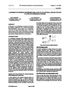
Figure 5. Normalized HSDPA cell throughput versus median normalized HSDPA packet bit rate for different levels of background traffic.
The assumed packet service is based on a simple packet download model. There, a user enters the system according to a Poisson process, downloads a file of a fixed size of 200 kbytes, and leaves the system as soon as the file has been successfully received. Only the downlink traffic is considered during the simulations. HSDPA Quality of Service (QoS) is evaluated based on the packet bit rate distribution. The packet bit rate is defined as the size of the packet in bits (1.6·106) divided by the packet delay, i.e. the time elapsed from a packet is requested at the server to the time when it is assumed to be correctly received by the user. The packet bit rate is evaluated for increasing load, i.e. the number of HSDPA users within the modeled building. HSDPA capacity is measured by the cell throughput, which is defined as the total number of delivered bits (packet traffic) during the simulation divided by the simulation time. In Figure 5, the two deployment options, “outdoor-toindoor” (O2I) and “dedicated in-building system” (DIBS), are compared. The different colors on the curves indicate the normalized level of background speech traffic within the macro cells. The dashed curves represent the results for the O2I scenario, while the solid curves present the simulation results for DIBS. As can be noticed, by deploying a dedicated inbuilding system to serve the HSDPA users, both the HSDPA quality and capacity can be improved considerably, which is in line with the analytical reasoning in Chapter II.
1
1.5 2 2.5 3 Normalized HSDPA Cell Throughput
3.5
4
4.5
Figure 6. Average total non-HS power in the overlaying macro cell as a function of the normalized HSDPA cell throughput.
IV. SIMULATION RESULTS
Speech Blocking 15 47% 71% 95%
Speech Blocking Probability [%]
The offered traffic consists of two services: speech and packet data. Speech users are always allocated a dedicated channel, while packet traffic is always transmitted over a HSDSCH. During the simulations, speech users are uniformly generated over the whole system area, but not within the modeled building. Data users, however, are generated only within the building. The users are initially connected to the closest cell, macro or in-building, from the path loss point of view. Furthermore, the users can set up soft handover connections towards any cells that have been identified by the soft handover algorithm.
0.5
10
5
0 0
0.5
1
1.5 2 2.5 3 Normalized HSDPA Cell Throughput
3.5
4
4.5
Figure 7. Simulation results for the speech user blocking probability as a function of the normalized HSDPA cell throughput.
The impact of βk,j is clearly visible in the O2I curves. The more background speech traffic there is, the less power is available for the HS-DSCH. As a result, the user bit rates and the overall cell throughput are reduced. This is also demonstrated in Figure 6, where the average total non-HS power for the overlaying macro cell is presented as a function of the normalized cell throughput. Again, the dashed curves on the left hand side of the figure are for O2I, while the solid curves going across the figure are for DIBS. It becomes obvious by looking at Figure 6 how the dedicated in-building system offloads the overlaying macro cell, resulting in lower total output power. Due to the considerably reduced Pnon-HS, the Grade of Service (GoS) is improved for the background speech users, i.e. the blocking probability becomes smaller for a certain offered load level. This is clearly demonstrated by the curves in Figure 7. The gain in total transmit power is caused by several factors: Firstly, since the in-building system is dominating inside the building, it will take care of the indoor traffic, and as a result of that the HS-DSCH and almost all of the A-DPCHs
the relatively small path losses between the mobiles and the inbuilding base station the thermal noise has only a very small impact on the total downlink interference. In all, the downlink CIR does not vary that much between the users served by the in-building system. A finding, which is well in line with the rough estimate shown in Figure 2.
Low HSDPA load 1 0.9 O2I 0.8 0.7
CDF
0.6 0.5 0.4
Top Floor
0.3 0.2 DIBS 0.1 0 0
100
200
300 400 500 600 700 HSDPA Packet Bit Rate [kbps]
800
900
1000
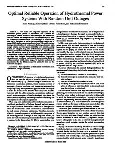
Figure 8. Distribution of the HSDPA packet bit rates per floor.
are no longer transmitted from the macro cell. Secondly, as a result of the lower macro cell transmit power, the intracell interference is reduced, which results in lower required transmit powers for the macro cell users. Thirdly, since the inbuilding system assumed in this paper is slightly leaking outside the building, it will attract some of the close-by background users to connect to it. This is the reason why the speech GoS is improved as a result of the introduction of the in-building system in a scenario without any indoor traffic. By looking at Figure 5 one can clearly notice how the performance of the dedicated in-building system does not depend on the overlaying macro cell load. The obvious reason for this is that the in-building system is sufficiently isolated from the macro cell. Thus, neither is the macro base station interfering the indoor users to a very large extent, nor is the inbuilding system attracting too many close-by macro cell users to connect to it. As a result, the values of Fk,j and βk,j do not remarkably depend on the macro cell load. Yet another interesting aspect of the indoor coverage is the obtained HSDPA performance per floor, namely the distribution of the HSDPA user bit rates. An example of such comparison is shown in Figure 8. There, the average background offered load is assumed to be equal to 71%. Furthermore, the offered HSDPA load is assumed to be low. As can be expected, for the outdoor-to-indoor scenario, the obtained packet bit rates are the higher the higher up in the building the user is located. This is obviously a direct result of the floor height gain, i.e. the fact that the path loss towards a macro base station is typically smaller on upper floors than on the ground floor. The distribution of the user packet bit rates looks quite different if the dedicated in-building system is deployed. Now, the packet bit rates are considerably improved throughout the building. Furthermore, the differences both within a floor and between the floors become smaller. Thus, the user QoS distribution over the building is much more uniform than in case of outdoor-to-indoor coverage. This is in general caused by the fact that the Fk,j values are small, and that as a result of
V. CONCLUSIONS In this paper two means to serve an indoor traffic hot spot were compared; outdoor-to-indoor coverage and through a dedicated in-building system. Simulation results show that a dedicated in-building system provides superior HSDPA quality and capacity within the hot spot area. This improvement is caused by the reduced path losses between the mobiles and the serving base stations, reduced relative intercell interference, improved downlink orthogonality and increased HS-DSCH transmit power. Furthermore, it has been demonstrated how the HSDPA performance depends on the location of the user within the building. In case of outdoor-to-indoor coverage, users on the upper floors will typically experience higher bit rates than users on the ground floor due to the differences in path losses towards the serving base station. However, in case of a homogenous dedicated in-building system, users on the ground floor will obtain a better HSDPA performance compared to users on the top floor. This is caused by the fact that the level of intercell interference is the higher the higher up in the building the user is located. REFERENCES [1]
A. Furuskär, S. Parkvall, M. Persson, M. Samuelsson, ”Performance of WCDMA high speed packet data”, in proceedings of VTC 2002 spring. [2] D. Hong, S. Choi, J. Cho, “Coverage and Capacity Analysis for the Multi-layer CDMA Macro/Indoor-Pico Cells”, in proceedings of ICC 1999. [3] H. Andersson, R. S. Karlsson, P. Larsson, P. Wikström, “Improving System Performance in a WCDMA FDD Network Using Indoor Pico Base Stations”, in proceedings of VTC 2002 spring. [4] J. Pérez-Romero, O. Sallent, R. Agusti, ”On the Capacity Degradation in W-CDMA Uplink/Downlink due to Indoor Traffic”, in proceedings of VTC 2004 fall. [5] B. Olin, H. Nyberg, M. Lundevall, ”A novel approach to WCDMA radio network dimensioning”, in proceedings of VTC 2004 fall. [6] G.E. Bottomley, T. Ottosson, Y.-P.E. Wang, “A Generalized RAKE Receiver for Interference Suppression”, IEEE Journal on Selected Areas in Communications, vol. 18, no. 8, pp. 1536-1545, August 2000. [7] E. Damosso, L. M. Correia (ed), COST 231 Final Report. [8] R. E. Schuh, M. Sommer, “W-CDMA coverage and capacity analysis for active and passive distributed antenna systems”, in proceedings of VTC 2002 spring. [9] C. Törnevik, J.-E. Berg, F. Lotse, M. Madfors, “Propagation Models, Cell Planning and Channel Allocation for Indoor Applications of Cellular Systems”, in proceedings of VTC 1993. [10] 3GPP TSG-RAN 25.943 V5.1.0, “Deployment aspects (Release 5)”, June 2002. [11] K. Hiltunen, M. Lundevall, S. Magnusson, ”Performance of Link Admission Control in a WCDMA System with HS-DSCH and Mixed Services” in proceedings of PIMRC 2004. [12] M. Kazmi, N. Wiberg, ”Scheduling Algorithms for HS-DSCH in a WCDMA Mixed Traffic Scenario”, in proceedings of PIMRC 2003.