Using Structured ASIC to Improve Design Productivity Yu-Wen Tsai, Kun-Chen Wu
Hui-Hsiang Tung, Rung-Bin Lin
Faraday Technology Corporation Hsin-Chu, 300, Taiwan {ywsay,kcwu}@faraday-tech.com
Department of Computer Science & Engineering Yuan Ze University Chung-Li, Tao-Yuan, 320, Taiwan
[email protected],
[email protected]
propose an implementation methodology based on MPCA and MPIO. The methodology can take advantages of both structured ASIC technology and conventional cell-based design flow.
Abstract—Structured ASIC is a well-developed technology that enables a shorter design Turn-Around-Time (TAT) as well as less Non-Recurring-Engineering (NRE) cost for very deep submicron designs. Since 2003, Faraday Technology has developed its own structured ASIC solutions. Based on its own competitive technology architecture, Faraday has proposed platform-based SoC solutions and realized more than 100 customer projects using its structured ASIC technology. This paper presents Faraday’s experience of using structured ASICs and shows Faraday’s efforts to establish a high-productivity structured ASIC flow.
Based on our structured ASIC technologies and conventional cell-based design flow, we have proposed platform-based SOC solutions, which can be customized for each application derivative to further reduce the NRE cost and time-to-market and also achieve maximum productivity. The rest of the paper is organized as follows. Section II describes Faraday’s structured ASIC core technology. Section III shows the proposed implementation methodology, including logic synthesis and physical design flows. Our platform-based SoC solutions are presented in Section IV. Concluding remarks are given in Section V.
Index Terms—Structured ASIC, TAT, NRE.
I.
INTRODUCTION
As semiconductor process technology migrates to very deep submicron nodes, increasing chip complexity, more complicated verification tasks, and shorter time-to-market have multiplied the difficulty of designing Systems-on-a-Chip (SoC) in the deep submicron era. Moreover, the Non-Recurring Engineering (NRE) cost, including implementation engineering efforts and mask tooling charges, increases significantly as the process technology scales. The NRE cost is too expensive for all but the very high-volume applications (quarter million plus units per year). Time-to-market pressure, frequent feature changes, and product derivatives further exacerbate the cost issues.
TABLE 1. ASIC DEVELOPMENT COST (US$) FPGA Total Design Cost Vendor NRE Cost of EDA Tools Man Power Price per Chip Unit Cost (Qty 1K) Unit Cost (Qty 5K) Unit Cost (Qty 500K)
A new breed of ASIC products, called “Structured ASIC”, can cut NRE expenses by more than 90% for derivative chips and speed up the time-to-market. As a result, the structured ASIC is very crucial to deep submicron designs. TABLE 1 is a cost comparison of a typical 1-million-gate design realized using FPGA, Structured ASIC, and cell-based ASIC implementations respectively based on a 0.13μm process. As one can see, structured ASIC has a cost advantage for low to medium volume applications. This trend will remain as process technology scales.
Structured ASIC Cell-based ASIC
$165K
$500K
$5.5M
None
$100K~$200K
$1M~$3M
$30K
$120K~$250K
> $300K
1 to 2 $200 ~ $1K
2 to 3 $30 ~ $150
5 to 7 $30
$1000
$500~$650
$55K
$220
$110~$150
$1.1K
$40
$21
$11
Source: Semiview, December 2003
II.
FARADAY’S STRUCTURED ASIC TECHNOLOGY
Structured ASIC technology is different from traditional cell-based ASIC. It contains an array of well-structured and optimized elements across an entire chip. The structured elements are designed for implementing the desired functions by making changes to few upper layer masks. Moreover, transistors realizing structured elements are prefabricated. Consequently, structured ASIC technology can save a significant amount of NRE cost and shorten time-to-market.
Since 2003, Faraday has proposed two structured ASIC technologies Metal Programmable Cell Array (MPCA) and Metal Programmable I/O (MPIO) [1] with a low NRE cost and an achievable performance closer to cell-based solutions. To achieve the quick usability of complex SOC design, we
25
ISIC 2009
for placement of structured elements. With the uniform array model, we can use an existing cell-based placement tool. With the above leading technologies, our structured ASIC implementation flow can be established using some conventional EDA tools [2] [3] [4].
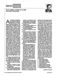
The structured ASIC technologies developed by Faraday include (1) Metal Programmable Cell Array (MPCA) library and (2) Metal Programmable I/O (MPIO) library. Figure 1 shows the cross section view of our structured ASIC technology based a 7-metal process technology. In this technology, we employ only three metal layers, M4, M5, and M6 to configure the functions of the library cells as well as for routing a design. By changing just one top metal mask, MPIO technology can support PCI33, PCI66, PCIX, SSTL2 class I/II, CMOS, and TTL I/O with different drive strengths and slew rate controls. Figure 2 shows a block diagram of Faraday’s MPIO.
III.
The implementation flow for our structured ASICs as shown in Figure 4 involves mainly four steps: logic synthesis, DFT insertion, placement & routing, and physical verification. The first step, logic synthesis, maps an RTL design into a netlist comprised of interconnected structured elements. DFT insertion adds scan circuitries to improve the testability and fault coverage. Placement & routing maps the structured elements onto array elements and also completes the routing. The final step is physical verification, also known as LVS/DRC. In each step, we use the existing cell-based EDA tools.
M7(thick)
Cell programming & inter-connect
VIA6
M6
VIA5
M5
Three metal programmable
VIA4
M4
IMPLEMENTATION METHODOLOGY
VIA3
M3
VIA2
M2
VIA1
M1 M1 CO n+
p+
n+
p+
p+
n+
n-well p-substrate
Figure 1. Programmable layers for 7-metal process in MPCA technology
I
Level Shifter (High Speed)
Pull-Hi Logic
Pull-Hi Pre-Driver
E
Level Shifter (High Speed)
Pull-Lo Logic
Pull-Lo Pre-Driver
EX
Level Shifter
Pull-Hi Pre-Driver
EY
Level Shifter
Pull-Lo Pre-Driver
EX1
Level Shifter
Pull-Hi Pre-Driver
EY1
Level Shifter
Pull-Lo Pre-Driver
SR
Level Shifter
O
BUF
Default Driver
I-V Adjuster
Figure 3. Our Structured ASIC mplementation flow IO
Our structured ASIC implementation flow is exactly the same as a conventional cell-based ASIC design flow because of Faraday competitive structured ASIC architectures. Moreover, Faraday’s has provided some physical and logic synthesis libraries that are able to work with existing commercial EDA tools to carry out its structured ASIC logic synthesis, simulation, DFT synthesis, etc. Our customers can implement their own chips based on Faraday structured ASIC technology using the same cell-based flow and do not have to purchase any new EDA tools.
XmA Driver
YmA Driver
CMOS Receiver
Level Shifter
SMT/PD
Level Shifter
IE
Level Shifter
PU
Level Shifter
PD
Level Shifter
OP-Amp Receiver
IV.
PLATFORM BASED SOC SOLUTIONS
With our MPCA and MPIO technologies, we offer two solutions to help designers implement the complex platformbased SOC designs with the 0.13μm and 90nm process technologies. These two solutions are (1) Faraday COMPOSER Platform and (2) Customer Own Application Specific Platform. We will describe these two solutions in detail in the following subsections.
Figure 2. The block diagram of metal-programmable I/O (MPIO)
In our structured ASIC technology, the transmission gate style instead of look-up table style is employed to build the structured elements. Based on the transmission gate style, we can use an existing logic synthesis EDA tool. We use the uniform array model [5] instead of non-uniform array model
26
block, embedded SRAM, analog IPs such as LVDS, and a configurable MPCA block. The configurable MPCA block is used to implement the timing control function of a TFT/LCD panel because the timing control function needs specific customization and constant revisions for each different panel manufacturer. Figure 6 shows the layout views of the DisplayComposer and NetComposer, respectively.
A. Faraday COMPOSER Platform COMPOSER, a structured ASIC technology based platform, includes embedded processors, embedded SRAM, external memory interface, analog IPs, and other peripherals such as interrupt controllers and DMA blocks. Besides the area occupied by silicon-proven IPs, the remaining area of a COMPOSER chip is reserved for MPCA structured elements which can be easily programmed to realize a variety of logic functions, with just employing three metal layers. Faraday has published a series of Application Specific Platform Solutions such as DisplayComposer for TFT/LCD display controllers, NetComposer for networking applications, Media-Composer for multimedia applications, and IAComposer for information appliance applications. Figure 4 shows the block diagram of IAComposer. The fixed body is implemented in traditional standard cells, and some existing silicon-proven IPs such CPU, ADC, DAC, PLL, etc. The IAComposer uses standard AHB/APH bus interface. Therefore, our customers can implement their own customized IPs using MPCA cells and integrate their IPs easily with existing IPs via standard AHB/APB bus interface.
Figure 6. The layout views of Display-Composer and Net-Composer
B. Customer Own Application Specific Platform Additionally, customers are able to create their own exclusive platforms according to application specific requirements. Figure 7 shows the layout view of a storage platform, which is co-developed by Faraday and a customer, where MPCA logic can be reconfigured to meet different flash memory specifications. This platform can be re-used for various generations of products.
Figure 4. The block diagram of IAComposer
Figure 7. The layout view of customer own storage platform
V.
CONCLUSIONS
Structured ASIC technology, known as a new approach to ASIC designs, can cut down NRE cost and offer an impressive reduction in time-to-market. Faraday has developed two structured ASIC technologies MPCA and MPIO. Based on these two technologies, Faraday has proposed a structured
Figure 5. The block diagram of DisplayComposer
Figure 5 shows the block diagram of DisplayComposer. The DisplayComposer consists of a conventional standard cell
27
ASIC based SoC solution. The solution provides different SoC design platforms or even customized platforms for various applications. With Faraday’s structured ASIC, we have experienced much shorter turn-around-time of complex SOC designs and hence significantly improved our design productivity.
[2] [3] [4] [5]
REFERENCES [1]
Faraday Structured ASIC Technology WWW site:
28
http://www.faraday-tech.com/html/products/structuredASIC.html Cadence SocEncounter User’s Guide and Document Reference Manual. 2008. Synopsys Design Compiler User’s Guide and Document Reference Manual.2008. Mentor Graphics Calibre User’s Guide and Document Reference Manual 2008. Kun-Chen Wu and Yu-Wen Tsai, “Structured ASIC: A Revolution or an Evolution,” in Proc. International Symposium on Physical Design, pp. 103-106, 2004.