A METHOD TO IMPROVE MICROGRID RELIABILITY BY OPTIMAL SIZING PV/WIND PLANTS AND STORAGE SYSTEMS Daniele MENNITI University of Calabria – Italy
[email protected]
Anna PINNARELLI University of Calabria – Italy
[email protected]
ABSTRACT In this paper a new methodology is proposed to determine the optimum configuration of a grid-connected hybrid Photovoltaic/Wind system. Based on an optimization process the developed methodology helps to obtain the optimal number of PV panels, wind turbines and storage units ensuring that the system total cost is minimized while guaranteeing a highly reliable source of load power.
Nicola SORRENTINO University of Calabria – Italy
[email protected]
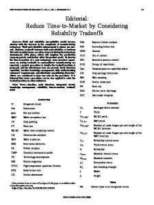
the energy surplus and to supply the load in case of low wind speed and/or low solar irradiation conditions. The DCAC converter (inverter) is used to interface the DC bus voltage and the DC battery voltage to the AC load requirements. The energy produced from each PV and/or wind source is transferred to the load by the DC-AC inverter, while the energy surplus is used to charge the batteries. If the energy generated by both generators and the battery capacity are not sufficient to load power the deficit will be taken from the grid.
INTRODUCTION In a Distributed Generation (DG) system smaller power sources, typically generating 1kW to 1MW located near to the loads, are used to provide the electrical energy to the consumers. A more recent concept is to group a cluster of loads and paralleled DG systems within a certain local area to form a MicroGrid (MG). The use of different energy sources allows to improve the efficiency and the reliability of the MG energy supply and reduces the energy storage requirements compared to systems comprising only one single renewable energy source. On the other hand, with the complementary characteristics between solar and wind energy resources for certain locations, hybrid photovoltaic/wind power generation systems with storage banks (HPWS) offer a high reliable source of load power. To use solar and wind energy resources more efficiently and economically, the optimal sizing of HPWS plays an important role [1-9]. The primary objective of this study is to outline a general methodology for determining the optimum size of a HPWS connected to the grid to guarantee an adequate reliability level of load power supply. In this study, the methodology adopted is based on the loss of power supply probability (LPSP) and the cost of components [2]. It consists of two steps: the first step is to find the optimum system configurations, meeting the required LPSP; in the second step, the optimal configuration is chosen among those meeting the desired LPSP with the lowest cost.
MODEL OF THE HYBRID PV_WIND SYSTEM WITH STORAGE DEVICES A block diagram of the proposed integrated hybrid PV /wind system is shown in Fig. 1. In order to extract the maximum available power from the wind and PV power sources, the choppers with MPPT (Maximum Power Point Tracker) technology are used. The battery is used to store
!
"
#
$
Fig. 1 Grid-connected Hybrid System
The PV System model PV module performance is highly influenced by weather conditions, especially solar radiation and temperature. Assuming that the modules work always at the point of maximum power, the equation for calculating the current and voltage IPV and VPV respectively at the point of working under arbitrary conditions can be expressed as reported in [4]. Let us consider a PV module of size MxN, which consists of N parallel strings with each string having M cells connected in series; the sum of the voltages across M cells in a string is the module voltage VPV. The module current IPV is determined by the sum of currents flowing through each string (i.e. N strings). The instantaneous power generated by the photovoltaic module with respect to the solar radiation G is obtained as: Ppv=Ipv*Vpv (1) In consequence of the different weather conditions at each hour in the observation interval time the power produced by the PV plant (Ppv(t)) is calculated according to (1).
The Wind energy conversion System model There are three main factors which determine the power output of a whole wind energy conversion system , i.e., the power output curve of a chosen wind turbine, the wind speed distribution of a selected site where the wind turbine is installed, and the hub height of the wind tower. The most
simplified model to simulate the power output of a wind turbine can be described by [3]:
(2) where Pr is the rated electrical power; Vcin is the cut-in wind speed; Vrat is the rated wind speed; and VCOU is the cut-off wind speed. For small-scale wind turbines, the cut-in wind speed is relatively smaller, and wind turbines can operate easily even when wind speed is not very high. In order to calculate the wind speed, V at the desired WG installation height H, which is usually different from the height corresponding to the wind speed input data, the exponential law is used: (3) where Vref is the reference (input) wind speed (m/s) measured at height Href (m) and is the power law exponent, ranging from 1/7 to 1/4. The hourly output of wind generator PWT(t) can be easily obtained by using the characteristic equation of the wind generator and average hourly wind speed at the hub height.
The Load Model The hourly load demand, Pload(t), determines the requirements of power supply from the hybrid system. The loads can be DC or AC. It is assumed a load profile varying over the observation interval time.
The Grid-connection model If grid is available, then utilizing renewable energy sources can only be justified on the basis that reduction in utility emissions is desirable. This awareness takes the form of a utility management program for promoting for environmentally friendly technologies on the customer side, the use of renewable energy may become attractive if in the future, customers would have to pay not only for the cost of generating the power they use, but also for its transmission, distribution and the indirect cost of environmental cleanup and health effects. The design variable in this case is the rating of the grid substation Rgr(kW), which makes the connection with the hybrid power system given g, the initial cost ( /kW), the total capital cost becomes g Rgr. With buy defining the cost of purchased electricity ( /kWh), the yearly costs would be [8]: (4) If regulations allow a utility to buy power from private power suppliers, then equation should modified as follows: (5)
!
"
#
$
The Storage device model At each hour, the excess power generated by the PV and wind generators can be utilized for charging the batteries whereas the stored energy can be discharged whenever there is a deficiency in power generation. When the power generated, by both the wind turbine and the PV array is not enough and the battery is discharged, the load will not be satisfied. Therefore, in consequence of the difference between total energy generated and load demand energy, the battery is in charging or discharging state. During the charging process, the available battery bank capacity at the time t can be calculated as follows [5]: Cbat(t)=Cbat(t-1)+(Ppv(t)+(PWT(t)-Pload(t)))* cha* t where Cbat(t) and Cbat(t -1) are the available battery bank capacity (W h) at the time t and (t- 1), respectively, Pload(t) is the power consumed by the load at the time t, ∆t is the simulation time step (∆t = 1 h), cha is the battery charging efficiency ranging from 0.65 to 0.85, depending on the charging current. In the case of (PWT < Pload) and (Ppv (Pload – PWT)) the batteries are in charge and the storage battery capacity at the time t is as follows: Cbat(t)=Cbat(t-1)+((Ppv(t)-(Pload(t)-PWT(t)))* cha* t); In the case of (PWT < Pload) , (Ppv < (Pload – PWT)) and (Rgr (Pload-(PWT+Ppv))) the batteries are still in charge and the storage battery capacity at the time t is as follows: Cbat(t)=Cbat(t-1)+(Rgr(t)-(Pload(t)-(PWT(t)+Ppv(t))))* cha * t ; The batteries are subject to the discharging stage in the case of (PWT < Pload), (Ppv < (Pload – PWT)) and (Rgr < (Pload+(PWT+Ppv))). In this case, indeed the renewable energy sources and the grid have not enough capacity to supply the load and the deficit will be supplied by the batteries . In this case the storage battery capacity is computed as follows: Cbat(t)=Cbat(t-1)+1/ dech*(Rgr(t)-(Pload(t)-PWT(t)+Ppv(t))))* t where dech is the battery discharging efficiency equal generally to 1. In all cases the storage battery capacity is subject to the following constraints: Cbatmin Cbat(t) Cbatmax where Cbatmax and Cbatmin are the maximum and minimum allowable storage capacities. Cbatmin is determined by the maximum allowable depth of battery discharge (DOD) as follows: Cbatmin=DOD*Cbat (6)
THE RELIABILITY HPWS MODEL BASED ON THE LPSP CONCEPT The LPSP technique is based on concept of the probability that an insufficient power supply results when the gridconnected hybrid system is unable to satisfy the load demand. It is a feasible measure of the system performance for an assumed or known load distribution: an LPSP of 0 means the load will always be satisfied; an LPSP of 1 means that the load will never be satisfied. There are four decision variables to improve the LPSP, i.e. the rating of the grid substation, the rated power of PV system, the rated power of
wind system, and the capacity of the battery bank. The goal is to find the trade-off between the LPSP and the minimization of the system total costs. At this scope, the objective function taken here is the system total cost, FC(x) ( ), which is the sum of the total capital cost function CT(x), the maintenance cost function CM(x), and the cost of installation CR(x) [2]:
where NPV,Pmax, NWTmax, Rgrmax, were calculated to meet individual requests of the load, while NBAT,Pmin and NBAT,Pmax were set to ensure the load autonomy minimum and a maximum of half an hour and three hours respectively.
(7) where x is the vector of the sizing variables x={NPV,p, NWT, NBAT,p, Rgr}, with NPV,p is the total number of parallel PV strings, NWT is the total number of wind turbines, NBAT,p is the total number of parallel battery strings and Rgr the energy to be purchased by grid. Thus, optimization procedure is achieved by minimizing the total cost function consisting of the sum of the individual system devices capital, the 20-year round maintenance costs and the installation cost:
In order to compute LPSP an hourly based analysis over the considered time interval has to be made. The power provided by the system at hour t, Pp(t), is determined as follows: n n (9) P (t ) = N i PV P i PV (t ) + N j WT P j WT (t ) + R
Fc( N PV , p , NWT , N BAT , P , Rgr ) =
n PV
N i PV (C i PV + 20M i PV ) +
i =1 nWT
(8)
N jWT (C jWT + 20M jWT + C j h + 20C j h ) +
j =1 n BAT
N k BAT (C k BAT + y k BAT C k BAT + (20 − y k BAT − 1) M k BAT ) +
k =1
(α Rgr − α sell Rexcess )(total number of hours) + 12α R gr DC
buy
where nPV, nWT, nBAT are the total number of PV panel types, wind turbine types and battery units types, respectively, and CiPV, CjWT, CkBAT are the corresponding capital costs ( ) and MiPV, MjWT, MkBAT are the corresponding maintenance costs per year ( /year). Chj is the WT tower capital cost ( ), Chmj is the WT tower maintenance cost per year ( /year) and ykBAT is the expected number of battery replacements during the 20-year system operation, because of limited battery lifetime. The costs of converters and of other components are included in the installation cost. Moreover, buy and sell are the costs of buying and selling of energy by the grid respectively, and DC the demand charge in /(KW/month). In order to extend the lifetime of the battery to the maximum, the charged quantity of the battery is subject to the following two constraints: Cbatmin Cbat(t) Cbatmax Then the optimization problem is formulated as follows: min Fc( N PV , p , NWT , N BAT , P , Rgr ) =
n PV
N i PV (C i PV + 20M i PV ) +
i =1 nWT
N jWT (C jWT + 20M
j
WT
+ C j h + 20C j h ) +
j =1 n BAT
N k BAT (C k BAT + y k BAT C k BAT + (20 − y k BAT − 1) M k BAT ) +
k =1
(α Rgr − α sell Rexcess )(total number of hours) + 12α R gr DC
buy
s.v. Cbat min ≤ Cbat (t ) ≤ Cbat max 0 ≤ N PV , p ≤ N PV , p max 0 ≤ NWT ≤ NWT max N BAT , p min ≤ N BAT , p ≤ N BAT , p max 0 ≤ Rgr ≤ Rgr max LPSP( N PV , p , NWT , N BAT , P , Rgr ) ≥ LPSPmin
!
"
#
$
LPSP formulation
pv
WT
I =1
j =1
p
gr
where t is the time unit of one hour on a observation interval time generally of ten years. For grid-connected applications, energy grid cost still represents the major economic restraints. It has sought to reduce as much as possible contribution of the grid, ensuring continuity in any event for the year. At this scope the following constraint is imposed: P(t)=Pp(t)-Pload(t) 0 If P(t) is 0 then the loads are supplied. On the contrary the energy is taken from the battery. The LPS (s) (Loss of Power Supply) is set to zero and if the storage capacity reaches a maximum value (Cbat Cab = max) it is calculated the energy surplus that will then be sold on the grid. If the energy generated by both generators is not sufficient to load power the deficit will be taken from the grid, which in turn could be sufficient charging batteries and setting LPS (t) = 0, or not then subjecting the battery to a discharge process. If the remaining charge in the battery is less than the minimum value the LPS (t) will be calculated as LPS (t) = Pload(t)-(PWT(t) + PPV(t) + RGR) otherwise will be set to zero. The value of LPSP is calculated as the ratio of the sum of all values of LPS (t) and the sum of all load requests:
The resolution approach
(10)
The approach used for the application of LPSP can be summarized in the following steps: 1. Initially the program requires the characteristics of the system components and calculates the minimum system configuration and maximum while meeting all the constraints imposed previously; 2. Starting from the minimal configuration thus obtained, calculate the power generated by the various components that varies with each hour with the weather conditions; 3. The value of LPSP defined as in (10) is calculated; 5. If LPSP obtained, is negative or equal to zero, the configuration is saved, and its cost is calculated and a new configuration will be analyzed. If this value is positive a new configuration will be analysed and the actual one is not saved. 6. Inside the set of feasible configurations the cheaper one will represent the solution of the optimization problem.
SIMULATION RESULTS The proposed model is applied to a location in Calabria, in the south of Italy. The PV data and the WG data refer to the real sun irradiation, temperature and wind measured. The data of the system components are specified in table I- II. TABLE I: Wind turbine and PV module characteristics Type
Wind
Layer
electronics
Type
PV
KYOCERA
Turbine
GE-10
Module
KC200GT
H (m)
6
Vpv_nom (V)
12
Pr (W)
1000
Imp (A)
7.61
Vcin (m/s)
3
Isc (A)
8.21
Vrate (m/s)
9
Voc (V)
32.9
Vcoff (m/s)
25
Vmp (V)
26.3
Cwg ( )
1200
0 (V/°C)
-0.123
Ctor ( )
0
0 (A/°C)
0.00318
TABLE II: Battery characteristics Type
Concorde battery PVX-1080T
Cb (Ah)
108
Vbat (V)
12
DOD
0.6
eff_charge_bat
0.8
Cba ( )
128
The maintenance cost of each unit per year was set at 1% of its capital cost; buy = 0.00050 / Wh and sell = 0.00038 / Wh respectively; the expected duration for the group of batteries was seen in 3 years with proper maintenance, then it is supposed to make 6substitutions and then Ybat = 6; the DC voltage has been set equal to 48 V; the wind turbine height has been set equal to 6 mt; the load power request has been considered variable as the load diagram reported in Fig. 2. Moreover, it was imposed a value of LPSP = 0. With respect to this restriction the configuration obtained will be able to ensure continuity of the load exercise to a minimum and a maximum of ½ hours and 3hours respectively, even in case of bad weather and contemporary failure of the grid.
Fig. 2 Load profile
!
"
#
$
Results of optimization for the system are: Rgr= 108(kW), NBAT,p=7, NBAT=28, NWT=12, NPV,p=7, NPV=28. To obtain that HPWS configuration a total cost equal to 60.911.282,48 has be made. It is worth noting that, despite the configuration obtained is that optima, the total cost of the system is high. This is because in order to obtain a high standard of safety, that is LPSP = 0, it was necessary the contribution of the grid for 5 KWh with a significant increase of the total costs.
REFERENCES [1] Borowy B. S., Salameh Z. M., “Methodology for optimally sizing the combination of a battery bank and PV array in a Wind/PV hybrid system”, IEEE Transactions on Energy Conversion, June 1996, Vol. 11, no 2. [2] Hongxing Yang, Wei Zhou, Lin Lu, Zhaohong Fang, “Optimal sizing method for stand-alone hybrid solar– wind system with LPSP technology by using genetic algorithm”, Elsevier Solar Energy n. 82, 2008, pp. 354367. [3] Yang H., Lu L., Zhou W.: A novel optimization sizing model for hybrid solar-wind power generation system.Solar Energy 2007, Vol 81, pp 76-84. [4] B. Ai, H. Yang, H. Shen, X. Liao: Computer-aided design of PV/wind hybrid system.Renewable Energy 28 (2003) 1491–1512. [5] S. Diaf, G. Notton, M. Belhamel, M. Haddadi, A. Louche : Design and techno-economical optimization for hybrid PV/wind system under various meteorological conditions. Applied Energy 85 (2008) 968–987. [6] Eftichios Koutroulis, Dionissia Kolokotsa,Antonis Potirakis, Kostas Kalaitzakis: Methodology for optimal sizing of stand-alone photovoltaic/wind-generator systems using genetic algorithms.Solar Energy 80 (2006) 1072–1088. [7] Rachid BELFKIRA, Omessad HAJJI, Cristian NICHITA, Georges BARAKAT: Optimal sizing of stand-alone hybrid wind/PV system with battery storage, European Conference on Power Electronics and applications, 2-5 Sept, 2007, 1-10. [8] Riad Chedid, Saifur Rahman: Unit sizing and control of Hybrid wind-solar power systems, IEEE Transactions on Energy Conversion, Vol. 12, No. 1, March 1997. [9] S. Diaf, M. Belhamel, M. Haddadi, A. Louche: Technical and economic assessment of hybrid photovoltaic/wind system with battery storage in Corsica island. Energy Policy 36 (2008) 743–754.