One notable exception is WarpPLS (available from: warppls.com), a new ..... Mexico. Guillermo Asper, U. of Brasilia, Brazil. Raquel Benbunan-Fich, City U. of New York, USA. Anita Blanchard ... Clovis Torres Fernandes, Institute of Aeronautical.
International Journal of e-Collaboration, 6(4), 1-11, October-December 2010 1
Using WarpPLS in E-collaboration Studies: An Overview of Five Main Analysis Steps Ned Kock, Texas A&M International University, USA
ABSTRACT Most relationships between variables describing natural and behavioral phenomena are nonlinear, with U-curve and S-curve relationships being particularly common. Yet, structural equation modeling software ������������� �� � � � � �� ������� ��� � ���� � ������� � ��� � � ���� ���� �� ��� � ���� � �� �� ���� consideration. This can lead to misleading results, particularly in multivariate and complex phenomena like those related to e-collaboration. One notable exception is WarpPLS (available from: warppls.com), a new ���� ��� �� �� � ������ � �������� � � ��� ����� � � �� � �� ��������� � � ���� �� � ��� ����� � �� �� ���� �� paper contributes to the literature on e-collaboration research methods by providing a description of the main features of WarpPLS in the context of an e-collaboration study. The focus of this discussion is on the software’s � ��� �� ����� ���� � ���������� � ��� ��� � ��������� �� ����� ��
�� �� ��� � �� ���� ������� ��� ��� ��� through which a structural equation modeling analysis is conducted through WarpPLS. Keywords:
Multivariate Statistics, Nonlinear Analysis, Partial Least Squares, Structural Equation Modeling, Virtual Teams, WarpPLS
INTRODUCTION Multivariate analysis methods are particularly useful because they allow for the estimation of relationships among numeric variables controlling for the effects of multiple variables at the same time (Hair et al., 1987). Three commonly used multivariate analysis methods are multiple regression, path analysis, and structural equation modeling (SEM). In multiple regression coefficients of association between one dependent variable and multiple independent or control variables are estimated all at once, as part of a multiple regresDOI: 10.4018/jec.2010100101
sion model. Those coefficients of association are standardized partial regression coefficients (Rencher, 1998), which are different from but analogous to Pearson correlation coefficients (Rosenthal & Rosnow, 1991). In path analysis, coefficients of association in several multiple regression models that are connected to each other are estimated all at once. The coefficients of association are of the same type as those generated by multiple regression analysis, but in path analysis they are usually referred to as path coefficients. Finally, in SEM, path analyses are conducted with various latent variables (LVs), which typically are perceptual variables that cannot be measured directly (e.g., perceived
Copyright © 2010, IGI Global. Copying or distributing in print or electronic forms without written permission of IGI Global is prohibited.
2 International Journal of e-Collaboration, 6(4), 1-11, October-December 2010
ease of use of an e-collaboration technology). In SEM each LV score is calculated as a weighted average of a set of variables, normally referred to as manifest variables or indicators, which are measured directly. Models can comprise a combination of multiple-indicator and singleindicator LVs in SEM. While many conditions for convergence exist for the calculation of LV scores in SEM, and thus many approaches to SEM exist, the quantitative methods literature often classifies SEM approaches into two main types: covariance and variance-based (Gefen et al., 2000; Haenlein & Kaplan, 2004). The latter is also known as the PLS-based or component-based approach to SEM (Chin et al., 2003), where PLS usually stands for “partial least squares” (even though in the original version of the approach, it stood for “projection to latent structures”). PLS-based SEM has several key advantages over covariance-based SEM, including the following: (a) it appears to always yield a solution, even in complex models; (b) it does not require variables to meet parametric analysis criteria, such as multivariate normality and large sample sizes; and (c) it enables the estimation of parameters in models with formative LVs and moderating effects. One disadvantage of PLSbased SEM is that it typically does not yield fit indices, which are useful in the assessment of the overall fit between a model with multiple LVs and the dataset used in the SEM analysis. Most relationships between variables describing natural and behavioral phenomena seem to be nonlinear, with U-curve and S-curve relationships being particularly common. Yet, typically neither PLS-based nor covariancebased SEM software estimate coefficients of association taking nonlinear relationships between LVs into consideration. The only type of nonlinearity that is typically estimated by commercially available and open-source SEM software, which is of a different kind than the one just described, is that caused by the consideration of moderating effects. Moderating effects are often described as one of two main types of sources of nonlinearity in SEM analysis. The other type is the
one associated with nonlinear relationships between LVs. One notable exception to the above limitation is a SEM software called WarpPLS (Kock, 2010), currently available (from: warppls.com) in its first release, version 1.0. The discussion presented here contributes to the literature on e-collaboration research methods by providing a description of the main features of WarpPLS, in the context of an e-collaboration study. The focus of this discussion, however, is more on the use of the software than on the e-collaboration study itself. Particular emphasis is placed on the five main steps through a SEM analysis is conducted with WarpPLS
The E-Collaboration Study Several screens are shown here summarizing analysis results based on data from an e-collaboration study. The study involved 290 teams tasked with developing new products, goods or services, in a variety of organizations. Data related to five LVs were collected as part of this study. The LVs are indicated here as “ECU”, “ECUVar”, “Proc”, “Effi”, and “Effe”. “ECU” refers to the extent to which electronic communication media were used by each team. “ECUVar” refers to the variety of different electronic communication media used by each team. “Proc” refers to the degree to which each team employed established project management techniques, referred to in the study as procedural structuring techniques. “Effi” refers to the efficiency of each team, in terms of task completion cost and time. “Effe” refers to the effectiveness of each team, in terms of the actual commercial success of the new goods or services that each team developed.
Distinctive Features of WarpPLS WarpPLS identifies nonlinear (or “warped”, hence the name of the software) relationships among LVs and corrects the values of path coefficients accordingly. WarpPLS is arguably the first SEM software to do this. Since most relationships between numeric variables are nonlinear, one could argue that WarpPLS
Copyright © 2010, IGI Global. Copying or distributing in print or electronic forms without written permission of IGI Global is prohibited.
International Journal of e-Collaboration, 6(4), 1-11, October-December 2010 3
finds the “real” relationships between LVs in a SEM analysis. Because of this, often path coefficients associated with strong real effects become higher than those estimated by other SEM software, in some cases going from nonsignificant to significant at the P lower than 1 percent level. The underlying algorithm employed by WarpPLS is PLS regression, whose main characteristic is its ability to minimize multicolinearity among LVs; even in the presence of overlapping manifest variables (or indicators). Additionally, WarpPLS offers the following features, which are largely absent from most, if not all, PLS-based SEM software packages available today. It estimates P values for path coefficients automatically, instead of providing only standard errors or T values, and leaving the user to figure out what the corresponding P values are. It also estimates several model fit indices, which have been designed to be meaningful in the context of PLS-based SEM analyses. WarpPLS automatically builds the indicators’ product structure underlying moderating relationships, and goes a little further. It shows those moderating relationships, related path coefficients, and related P values in a model graph as links between LVs and direct links. The latter connect pairs of LVs, while the former connect LVs and direct links between pairs of LVs. The software allows users to view scatter plots of each of the relationships among LVs (when they are connected through arrows in the model), together with the regression curves that best approximate those relationships, and save those plots as .jpg files for inclusion in research reports. It also calculates variance inflation factor (VIF) coefficients for LV predictors associated with each LV criterion. This allows users to check whether some predictors should be removed due to multicolinearity. This feature is particularly useful with LVs that are measured based on only 1 or a few indicators, since they are potential sources of colinearity.
Warping from Conceptual Perspective What WarpPLS does when it “warps” relationships is relatively simple at a conceptual level. It identifies a set of functions F1(LVp1), F2(LVp2) … that relate blocks of LV predictors (LVp1, LVp2 ...) to a criterion LV (LVc) in this way: LVc = p1*F1(LVp1) + p2*F2(LVp2) + … + E. In the equation above, p1, p2 ... are path coefficients, and E is the error term of the equation. All variables are standardized. Any model can be decomposed into a set of blocks relating LV predictors and criteria in this way. WarpPLS implements two warp algorithms, or modes, which can be selected by the user: Warp2 and Warp3. In the Warp2 mode, the functions F1(LVp1), F2(LVp2) ... take the form of U curves (also known as J curves); defaulting to lines, if the relationships are actually linear. In the Warp3 mode, the functions F1(LVp1), F2(LVp2) ... take the form of S curves; defaulting to U curves or lines, if the relationships follow U-curve patterns or are linear, respectively. S curves are curves whose first derivative is a U curve. Similarly, U curves are curves whose first derivative is a line. U curves seem to be the most commonly found in natural and behavioral phenomena. S curves are also found in many natural and behavioral phenomena, but apparently not as frequently as U curves. U curves can be used to model most of the commonly seen functions in natural and behavioral studies, such as logarithmic, exponential, and hyperbolic decay functions. For these common types of functions, S-curve approximations will usually default to U curves. Typically, the more the functions F1(LVp1), F2(LVp2) ... look like curves, and unlike lines, the greater is the difference between the path coefficients p1, p2 ... and those that would have been obtained through a strictly linear analysis. So, what WarpPLS does is not unlike what a researcher would do if he or she modified predictor LV scores prior to the calculation
Copyright © 2010, IGI Global. Copying or distributing in print or electronic forms without written permission of IGI Global is prohibited.
4 International Journal of e-Collaboration, 6(4), 1-11, October-December 2010
of path coefficients using a function like the logarithmic function. An example is provided in the equation below, where a logarithmic transformation is applied to LVp1.
WarpPLS however, does that automatically, and for a much wider range of functions, since a fairly wide range of functions can be modeled as U or S curves. Exceptions are complex trigonometric functions, where the dataset comprises many cycles. These require different methods to be properly modeled, such as Fourier analyses methods, and are usually outside the scope of SEM. As mentioned earlier, often the path coefficients p1, p2 ... will go up in value due to warped analysis, but that may not always be the case. Given the nature of multivariate analysis, an increase in a path coefficient may lead to a decrease in a different path coefficient, for predictor LVs associated with the same criterion LV, because each path coefficient in a block is calculated in a way that controls for the effects of the other predictor LVs. That is, in any given block of LVs, the predictor LVs “compete” for the explained variance in the criterion LV.
Project files may be created with one name, and then renamed using Windows Explorer or another file management tool. Upon reading a project file that has been renamed in this fashion, the software will detect that the original name is different from the file name, and will adjust the name of the project file accordingly. Different WarpPLS users can easily exchange project files electronically if they are collaborating on a SEM analysis project. This way they will have access to all of the original data, intermediate data, and SEM analysis results in one single file. Project files are relatively small. For example, a complete project file of a model containing 5 LVs and 32 indicators will typically be only approximately 200 KB in size. Simpler models may be stored in project files as small as 50 KB. The reason for the small size of project files is that all of the SEM analysis results are stored in a format that allows for their rendering every time they are viewed. Plots of nonlinear relationships, for example, are not stored as bitmaps, but as equations that allow WarpPLS to re-create those plots at the time of viewing. The rendering is fast enough to give the user the impression that an existing plot is being displayed.
STEP 1: OPEN OR CREATE A PROJECT FILE
STEP 2: READ THE RAW DATA USED IN THE SEM ANALYSIS
WarpPLS conducts an analysis through five well defined steps. Through Step 1, the user will open or create a project file to save his or her work (see Figure 1). Project files are saved with the “.prj” extension, and contain all of the elements needed to perform a SEM analysis. That is, they contain the original data used in the analysis, the graphical model, the inner and outer model structures, and the results. Once an original data file is read into a project file, the original data file can be deleted without effect on the project file. The project file will store the original location and file name of the data file, but it will no longer use it.
Through Step 2, the user will read the raw data used in the SEM analysis (see Figure 2). While this should be a relatively trivial step, it is in fact one of the steps where users have the most problems with other SEM software. Often a SEM software application will abort, or freeze, if the raw data is not in the exact format required by the SEM software, or if there are any problems with the data, such as missing values (empty cells). WarpPLS employs an import wizard that avoids most data reading problems, even if it does not entirely eliminate the possibility that a problem will occur. Click only on the “Next” and “Finish” buttons of the file import wizard,
LVc = p1*log(LVp1) + p2*LVp2 + … + E.
Copyright © 2010, IGI Global. Copying or distributing in print or electronic forms without written permission of IGI Global is prohibited.
International Journal of e-Collaboration, 6(4), 1-11, October-December 2010 5
Figure 1. Step 1 window
and let the wizard do the rest. Soon after the raw data is imported, it will be shown on the screen, and the user will be given the opportunity to accept or reject it. If there are problems with the data, such as missing column names, simply click “No” when asked if the data looks correct. Raw data can be read directly from Excel files, with extension “.xls”, or text files where the data is tab-delimited or comma-delimited. When reading from an “.xls” file, make sure that the spreadsheet file has only one worksheet – the worksheet that contains the data. If the spreadsheet has multiple worksheets, Step 2 will most likely fail. Raw data files, whether Excel or text files, must have indicator names in the first row, and numeric data in the following rows. They may contain empty cells, or missing values; these will be automatically replaced with column averages in a later step. One simple test can be used to try to find out if there are problems with a raw data file. Try to open it with a spreadsheet software (e.g., Excel), if it is originally a text file; or to try to
create a tab-delimited text file with it, if it is originally a spreadsheet file. If the user tries to do either of these things, and the data looks messed up (e.g., corrupted, or missing column names), then it is likely that the original file has problems, which may be hidden from view. For example, a spreadsheet file may be corrupted, but that may not be evident based on a simple visual inspection of the contents of the file.
STEP 3: PRE-PROCESS THE DATA FOR THE SEM ANALYSIS In Step 3 the raw data will be pre-processed for the SEM analysis. This is mostly an automatic process, requiring only a few button clicks from the user. This step will correct problems with the data, such as identical column names, columns with zero variance, and missing values. This step will also let the user know if the data has rank problems, which usually happen when the sample size is small. (A related cause of rank problems is a sample with many repeated
Copyright © 2010, IGI Global. Copying or distributing in print or electronic forms without written permission of IGI Global is prohibited.
6 International Journal of e-Collaboration, 6(4), 1-11, October-December 2010
Figure 2. Step 2 window
or linearly dependent values on different rows or columns, which sometimes is an indication of data fabrication.) If there are rank problems, that does not mean that the user cannot proceed with the SEM analysis, but the results may be unstable and, in some cases, unreliable. In many cases, however, rank problems will be reported, and the results of the ensuing SEM analysis will still be reliable. This is due to the general robustness of PLS-based methods for SEM analysis. At the end of this step, a window will be displayed with the pre-processed data, which will be standardized. Standardized data columns have means that equal zero and standard deviations that equal one. Previously missing values will be shown as zeroes, since they were replaced with the averages (or means) of the columns. Standardized data usually ranges from -4 to 4, with outliers usually assuming values
toward the left or right end of those extremes, sometimes beyond -4 or 4. Typically the user will accept the data, and move on to the next step. If the data looks messed up, do not accept it; click on the “No” button when asked if the data looks correct. If there are problems in this step, they will usually be related to problems with the raw data file. The users should check that file, and see if he or she can correct those problems.
STEP 4: DEFINE THE VARIABLES AND LINKS IN THE SEM MODEL In Step 4 the user will define the LVs and links in the SEM model. The user will define the LVs by selecting the indicators that are associated with them, and the measurement method used – either formative or reflective. The process of
Copyright © 2010, IGI Global. Copying or distributing in print or electronic forms without written permission of IGI Global is prohibited.
International Journal of e-Collaboration, 6(4), 1-11, October-December 2010 7
defining the LVs in a SEM model in this fashion is often called “defining the outer model”, in SEM lingo. Model links can be of two types, direct and moderating links. Direct links connect pairs of LVs. Moderating links connect LVs and direct links; that is, they refer to effects in which a LV moderates the relationship between a pair of LVs. The process of defining model links is often referred to as “defining the inner model”. The window used to create or edit a model is shown in Figure 3. A model can be edited if it has been created and saved before as part of a project. While editing or creating a model the user can choose from a number of menu options related to overall model functions, LV functions, direct link functions, and moderating link functions. As with other windows in WarpPLS, there is a help menu option that provides
access to this manual and to a context-specific help file; both displayed as PDF files. A guiding text box is shown at the top of the model editing and creation window. The content of this guiding text box changes depending on the menu option the user chooses, guiding the user through the sub-steps related to each option. For example, if the user chooses the option “Create latent variable”, the guiding text box will change color, and tell the user to select a location for the LV on the model graph. Direct links are displayed as full arrows in the model graph, and moderating links as dashed arrows. Each LV is displayed in the model graph within an oval symbol, where its name is shown above a combination of alphanumerical characters with this general format: “(F)16i”. In this example, the “F” refers to the measurement model; where “F” means formative, and
Figure 3. Create or edit the SEM model window
Copyright © 2010, IGI Global. Copying or distributing in print or electronic forms without written permission of IGI Global is prohibited.
8 International Journal of e-Collaboration, 6(4), 1-11, October-December 2010
“R” reflective. The “16i” reflects the number of indicators of the LV, which in this case is 16.
STEP 5: PERFORM THE SEM ANALYSIS AND VIEW THE RESULTS Step 5 performs the SEM analysis based on the model created in Step 4. After the user clicks on the button to perform the SEM analysis, the software will show a wait bar. This wait bar will update the user on the progress of the SEM analysis, which usually will take only a few seconds for simple to moderately complex models. As soon as the SEM analysis is completed, the software will show the results in graphical format on a window. That window also has menu options that allow the user to view more details about the results, including some that are not shown on the graph (e.g., reliability measures), and also save the results into tab-delimited text files. WarpPLS uses algorithms that are fairly computing intensive, in some cases employing multiple optimization sub-algorithms in each sub-step. Thus, the speed with which the analysis is conducted is a little lower than some other publicly available SEM software. The differences in speed are not significant though, and normally the results generated by WarpPLS are more complete, and in many cases more reliable. For example, WarpPLS calculates model fit indices, as well as P values for most of its parameter estimates. Publicly available PLS-based SEM software usually do not provide those. Some model elements may reduce the speed of the SEM analysis more than others. These are: formative LVs with many indicators and, more generally, LVs with many indicators (even if they are reflective); moderating effects, particularly if they associate LVs with many indicators; setting the number of resamples for bootstrapping as 200 or higher; and using jackknifing as the resampling method, if the sample size is larger than 200.
In jackknifing, the number of resamples equals the sample size, which is why using jackknifing as the resample method may reduce the speed of the SEM analysis with large samples. Generating resamples and running calculations on them is one of the most computing intensive sub-steps of the SEM analysis. However, jackknifing often produces more stable parameter estimates with warped analysis. So there is a tradeoff between speed and reliability when warping algorithms are being used. This tradeoff may tip the balance in favor of using jackknifing, alone or in addition to bootstrapping, even if the user has to wait longer for the results.
Viewing the Results of the SEM Analysis As soon as the SEM analysis is completed, WarpPLS shows the results in graphical format on a window, which also contains a number of menu options that allow the user to view and save more detailed results (see Figure 4). The graph with the results shows path coefficients, respective P values, and R-squared coefficients. The “Save” menu options allow users to save all of the results that they can view, with the majority of those results saved under the option to save all model estimates into a tabdelimited text file. Additionally, users can save the factor scores calculated for each LV; these can be useful in multi-level SEM analyses. The path coefficients are noted as beta coefficients. “Beta coefficient” is another term often used to refer to path coefficients in PLS-based SEM analysis; this term is commonly used in multiple regression analysis. The P values are displayed below the path coefficients, within parentheses. The R-squared coefficients are shown below each endogenous LV (i.e., a LV that is hypothesized to be affected by one or more other LVs), and reflect the percentage of the variance in the LV that is explained by the LVs that are hypothesized to affect it. To facilitate the visualization of the results, the path coefficients and P values for moderating effects are shown in a way similar to the correspond-
Copyright © 2010, IGI Global. Copying or distributing in print or electronic forms without written permission of IGI Global is prohibited.
International Journal of e-Collaboration, 6(4), 1-11, October-December 2010 9
Figure 4. View and save results window
ing values for direct effects, namely next to the arrows representing the effects.
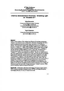
INTERPRETING THE U AND S CURVES GENERATED BY WARPPLS Linear relationships between pairs of LVs, that is, those relationships best described by a line, are relatively easy to interpret. They suggest that an increase in one variable either leads to an increase (if the slope of the line is positive) or decrease (if the slope is negative) in the other variable. Nonlinear relationships provide a much more nuanced view of the data, but at the same time are much more difficult to interpret. Figure 5 shows an S curve that is fitted to the data represented by the dots (or small circles) plotted in a scattered way on the graph. The LVs are “ECU”, the extent to which electronic communication media are used by various teams charged with developing a new product; and “Effi”, the efficiency of the teams.
As can be seen, the S curve is actually a combination of two U curves, one straight and the other inverted, connected at an inflection point. The inflection point is the point at the curve where the curvature, or second derivative of the S curve, changes direction. The inflection point is located at around minus 1 standard deviations from the “ECU” mean. That mean is at the zero mark on the horizontal axis, since the data shown is standardized. Because an S curve is a combination of two U curves, we can interpret each U curve section separately. A straight U curve, like the one shown on the left side of the graph, before the inflection point, can be interpreted as follows. The first half of the U curve goes from approximately minus 3.4 to minus 1.9 standard deviations from the mean, at which point the lowest team efficiency value is reached for the U curve. In that first half of the U curve, an increase in electronic communication media use leads to a decrease in team efficiency. After that first half, an increase in electronic communication media use leads to an increase in team efficiency.
Copyright © 2010, IGI Global. Copying or distributing in print or electronic forms without written permission of IGI Global is prohibited.
10 International Journal of e-Collaboration, 6(4), 1-11, October-December 2010
Figure 5. S curve relating two LVs from an e-collaboration study
One interpretation is that the first half of the U curve refers to novice users of electronic communication media. That is, the process of novice users struggling to use more and more intensely electronic communication media, which they are not familiar with, ends up leading to efficiency losses for their teams. At a certain point, around minus 1.9 standard deviations, that situation changes, and the teams start to really benefit from the use of electronic communication media, possibly because the second half of the U curve refers to users with more experience using the electronic communication media. The interpretation of the second, inverted U curve, should be done in a similar fashion. As can be inferred from this example, it is not easy to interpret nonlinear relationships. But the apparent simplicity of linear estimations of nonlinear relationships, which is usually what is done by other SEM software, is nothing but a mirage.
REFERENCES Chin, W. W., Marcolin, B. L., & Newsted, P. R. (2003). A partial least squares latent variable modeling approach for measuring interaction effects: Results from a Monte Carlo simulation study and an electronic-mail emotion/adoption study. Information Systems Research, 14(2), 189–218. doi:10.1287/ isre.14.2.189.16018 Gefen, D., Straub, D. W., & Boudreau, M.-C. (2000). Structural equation modeling and regression: Guidelines for research practice. Communications of the AIS, 4(7), 1–76. Haenlein, M., & Kaplan, A. M. (2004). A beginner’s guide to partial least squares analysis. Understanding Statistics, 3(4), 283–297. doi:10.1207/ s15328031us0304_4 Hair, J. F., Anderson, R. E., & Tatham, R. L. (1987). Multivariate data analysis. New York: Macmillan. Kock, N. (2010). WarpPLS 1.0 User Manual. Laredo, TX: ScriptWarp Systems. Rencher, A. C. (1998). Multivariate statistical inference and applications. New York: John Wiley & Sons. Rosenthal, R., & Rosnow, R. L. (1991). Essentials of behavioral research: Methods and data analysis. Boston: McGraw Hill.
Copyright © 2010, IGI Global. Copying or distributing in print or electronic forms without written permission of IGI Global is prohibited.
International Journal of e-Collaboration, 6(4), 1-11, October-December 2010 11
Ned Kock is Professor of Information Systems and Director of the Collaborative for International Technology Studies at Texas A&M International University. He holds degrees in electronics engineering (B.E.E.), computer science (M.S.), and management information systems (Ph.D.). Ned has authored and edited several books, including the bestselling Sage Publications book titled Systems Analysis and Design Fundamentals: A Business Process Redesign Approach. He has published his research in a number of high-impact journals including Communications of the ACM, Decision Support Systems, European Journal of Information Systems, European Journal of Operational Research, IEEE Transactions (various), Information & Management, Information Systems Journal, Journal of the Association for Information Systems, MIS Quarterly, and Organization Science. He is the Founding Editor-in-Chief of the International Journal of e-Collaboration, Associate Editor for Information Systems of the journal IEEE Transactions on Professional Communication, and Associate Editor of the Journal of Systems and Information Technology. His main research interests are biological and cultural influences on humantechnology interaction, non-linear structural equation modeling, electronic communication and collaboration, action research, ethical and legal issues in technology research and management, and business process improvement.
Copyright © 2010, IGI Global. Copying or distributing in print or electronic forms without written permission of IGI Global is prohibited.
IJeC Editorial Board Editor-in-Chief:
Ned Kock, Texas A&M International U., USA
Associate Editors:
J. Roberto Evaristo, 3M Company, USA Jane Fedorowicz, Bentley U., USA Jerry Fjermestad, New Jersey Institute of Technology, USA Stephen Hayne, Colorado State U., USA Surinder S. Kahai, State U. of New York at Binghamton, USA Robert J. McQueen, U. of Waikato, New Zealand Bjorn Erik Munkvold, U. of Agder, Norway John T. Nosek, Temple U., USA Craig Standing, Edith Cowan U., Australia Gert-Jan de Vreede, U. of Nebraska at Omaha, USA Jeffrey Wong, U. of Nevada Reno, USA
International Advisory Board: Richard L. Baskerville, Georgia State U., USA Nik Bessis, U. of Bedfordshire, UK David Gefen, Drexel U., USA Joey F. George, Florida State U., USA Varun Grover, Clemson U., USA Donald A. Hantula, Temple U., USA Sid Huff, Victoria U. of Wellington, New Zealand Julie E. Kendall, Rutgers U., USA Marshall Scott Poole, U. of Illinois at Urbana-Champaign, USA Cynthia Ruppel, Nova Southeastern U., USA Todd Watkins, Lehigh U., USA Editorial Assistant:
Murad Moqbel, Texas A&M International U., USA
IGI Editorial:
Heather A. Probst, Director of Journal Publications Jamie M. Wilson, Journal Development Editor Ron Blair, Journal Editorial Assistant Chris Hrobak, Journal Production Lead Gregory Snader, Production Assistant Brittany Metzel, Production Assistant
International Editorial Review Board: Fran Ackermann, U. of Strathclyde, Scotland Macedonio Alanis, Monterrey Institute of Technology, Mexico Guillermo Asper, U. of Brasilia, Brazil Raquel Benbunan-Fich, City U. of New York, USA Anita Blanchard, U. of North Carolina Charlotte, USA Karin Breu, U. of Oxford, UK Kelly Burke, U. of Hawaii, USA Ana R. Del Aguila-Obra, U. of Malaga, Spain Dorrie DeLuca, U. of Delaware, USA Brian Detlor, McMaster U., Canada Antonio Dias de Figueiredo, U. of Coimbra, Portugal Kevin Dow, U. of Alaska, USA Clovis Torres Fernandes, Institute of Aeronautical Technology, Brazil K. Dale Foster, Memorial U. of Newfoundland, Canada Susan Gasson, Drexel U., USA Alexandre Reis Graeml, Federal Center of Technological Education at Curitiba, Brazil Lewis Hassell, Drexel U., USA Richard Hicks, Texas A&M International U., USA M. Gordon Hunter, U. of Lethbridge, Canada Rajiv Kohli, The College of William & Mary, USA Christine Kydd, U. of Delaware, USA
IGIP
Isidro Laso-Ballesteros, European Commission, Belgium Annette Mills, U. of Canterbury, New Zealand Hector Munoz-Avila, Lehigh U., USA Fred Niederman, Saint Louis U., USA Rosalie J. Ocker, Pennsylvania State U., USA Antonio Padilla-Melendez, U. of Malaga, Spain Niki Panteli, U. of Bath, UK Sajda Qureshi, U. of Nebraska at Omaha, USA Richard R. Reilly, Stevens Institute of Technology, USA Nicolau Reinhard, U. of Sao Paulo, Brazil Kai Riemer, U. of Sydney, Australia Nicholas C. Romano, Oklahoma State U., USA Anne C. Rouse, Deakin U., Australia Paulo Rupino da Cunha, U. of Coimbra, Portugal Cynthia Ruppel, U. of Alabama in Huntsville, USA Anne F. Rutkowski, Tilburg U., The Netherlands Steven D. Sheetz, Virginia Polytechnic Institute and State U., USA Louise Soe, Cal Poly Pomona, USA Jacques Verville, U. of British Columbia, Canada Anthony Wensley, U. of Toronto, Canada E. Vance Wilson, Arizona State U., USA Oliver Yao, Lehigh U., USA Pak Yoong, Victoria U. of Wellington, New Zealand
IGI PUBLISHING WWW.IGI-GLOBAL.COM