24th Annual INCOSE International Symposium (IS2015) Seattle, WA, July 10 – 16, 2015
Utilizing MBSE Patterns to Accelerate System Verification David Cook Moog Aircraft Group
[email protected]
William D. Schindel ICTT System Sciences
[email protected]
Copyright © 2015 by David Cook and William D. Schindel. Published and used by INCOSE with permission.
Abstract. In aerospace, automotive, health care, and other domains, the capability to effectively plan and perform system verification tests is increasingly a strategic differentiator. This paper reports on methods used to improve effectiveness of complex aircraft system tests, the gains achieved, and their connection to underlying methods and trends. These include use of Model-Based Systems Engineering (MBSE), leveraged by Pattern-Based Systems Engineering (PBSE) to generate configurable, re-usable system models--the focus of the INCOSE MBSE Patterns Challenge Team. (Patterns Challenge Team, 2013-2015) Distinctive aspects include (1) use of configurable, model-based patterns of system descriptions, including configurable system verification tests, (2) improved ability of model-based descriptions to integrate modeling tools and automated systems for test management, (3) use of models to describe both system under development and the development process, and (4) ability of these models to be integrated with other system life cycle management processes and information systems, for increased leverage.
I.
Introduction
Enterprises involved in the development of technological systems have significant intellectual capital that has been accumulated through the execution of numerous development projects (Sherey, 2006). Regardless of the methods employed, this existing knowledge is a key asset in the development of new systems. The utilization of model-based system patterns and Pattern Based Systems Engineering processes provide a disciplined and systematic approach to maximize the effective use of this intellectual capital in the development of new systems. Coupled with the capabilities of modern MBSE tools and techniques, the application of pattern based MBSE holds the promise of significant improvements in the development of modern technological systems. This paper examines the application of model based system patterns to accelerate the verification of modern technological systems. The particular example chosen for this paper is the testing of a safety critical aircraft subsystem, namely the flight control actuation system.
II.
Challenges and Opportunities
It is understandable that the development of safety critical systems tends to be very risk averse. Processes for the development of safety critical aircraft systems are subject to scrutiny by the aircraft manufacturers (customers) and certification authorities to ensure that the development processes do not introduce unintended hazards into the system. For safety critical systems, such as flight control actuation, modeling provides the ability to improve the requirements quality and overall system design integrity. However, regardless of the design rigor, extensive verification (primarily testing or combination of analysis and test) is required to verify the system meets the functional and safety related requirements. The effort required to develop and execute a rigorous test program results in significant development cost. Testing cost can be
24th Annual INCOSE International Symposium (IS2015) Seattle, WA, July 10 – 16, 2015 20% to 50% of development effort (excluding hardware manufacturing costs) in many cases. Cutting testing costs without sacrificing test effectiveness can result in significant competitive advantages. (Cook, 2014) A primary goal of MBSE is to utilize the system models to capture and communicate all system related information in a clear and unambiguous fashion. If this can be accomplished with models then the documents used in traditional systems engineering are no longer necessary as the prime repository of information—they instead become snapshot artifacts that are views of the primary model database at the times of key milestones. The system model supersedes all the previous document artifacts as the most fundamental representation, and this model can be made to formally include model-based prose requirements and similar structures (Schindel, 2005). The current state of the industry and the extensive formal documentation associated with safety critical aircraft systems necessitate the use of conventional documents for many of the system development artifacts. As such, any MBSE implementation must be compatible with an environment where conventional engineering documentation is required. For verification tests, this includes formal test procedure and report documents.
III. MBSE and Patterns III.1 MBSE Improves Basic Representation Model-Based Systems Engineering (MBSE) changes and improves how we represent systems (Schindel, 2014). This applies to more than just the Product System to be developed. Benefits can also be gained from explicit models of different systems across the Product System’s life cycle, potentially including: The Product System itself, along with aspects of the larger Application Domain System in which it will serve (*) The Test System that will perform formal verification tests (*) Other aspects of the System of Development (e.g., the ISO15288 Technical Processes) The Manufacturing System (the System of Production) that instantiates the Product The Distribution System (including installation) that distributes the Product The Operations System that helps support in-service use of the Product The Maintenance System that helps maintain the Product The Decommissioning and Disposal System Those marked (*) above are the focus of this paper. Basic benefits of using MBSE to represent a Product System under development are becoming better known. For example, when compared to earlier traditional prose approaches, model-based requirements are generally: more explicit, less ambiguous, more likely to be interpreted consistently; easier to audit for completeness and correctness; more objectively interpreted for planning of test. (Schindel, 2005, 2014) These general benefits apply across a variety of contemporary modeling languages and supporting tools. They are amplified when applied using the underlying S*Metamodel of Figure 1 (Schindel, 2014). The S*Metamodel is generic information model that can be used to represent systems. The metamodel is tool agnostic and as such can be applied using a variety of languages and commercially available engineering tools. System models that conform to the S*Metamodel framework are referred to as S*Models. Such S*Models associate system
24th Annual INCOSE International Symposium (IS2015) Seattle, WA, July 10 – 16, 2015 requirements with physical Interactions (Schindel, 2013), and treat requirements as parameterized “transfer functions” (Schindel, 2005). Beyond the aerospace example of Section IV, these techniques are currently being demonstrated by the INCOSE Patterns Challenge Team, across multiple languages, tools, and domains (Patterns Challenge Team, 2013-2015). The S*Metamodel captures relationships between stakeholder features, functional interactions, requirements, architectural elements, etc. in a manner that provides a powerful foundation for the creation of configurable system patterns. Stakeholder Requirement Statement
Stakeholder World Language
attribute
Stakeholder
Feature attribute
Functional Interaction (Interaction)
High Level Requirements
“A” Matrix Couplings Technical World Language
BB Detail Level Requirements
Technical Requirement WB Statement attribute
High Level Design
State
System
Interface
System of Access
Input/ Output
BB (logical system)
Functional WB Role attribute
(physical system)
Design Constraint Statement
Design Component
attribute
“B” Matrix Couplings
attribute
Figure 1: Underlying S*Metamodel Summary, Language & Tool Independent
III.2 MBSE Improves Test Representation When MBSE is based on the S*Metamodel, all system requirements are seen to be described in the context of physical Interactions (exchanges of energy, force, mass, or information) with external domain actors, and each of the interacting entities has assigned Functional Roles that are modeled. As shown in Figure 2, this means that not only the requirements on the system under test are captured—so also are the related requirements (which could be called assumed behaviors) of the external systems. This has several advantages, but for purposes of this paper a key advantage is that it provides candidate behaviors of the Test System that will exercise the system under test. Having these role-based behaviors linked together as Interactions in the model from the outset reduces the effort of coordinating the test protocol with the requirements being tested. Since the Test System should also measure and capture the behavior of the System Under Test, this also provides an indication of expected behavior during test, for comparison. Product in Application Environment
Requirements Allocated to External Actors
External Actor 1
Requirements Allocated to Product System
External Actor 3
Product System External Actor 2
External Actor 4
Behavior Expected of Product System During Test, for Comparison by Test System Test System
Simulation Behavior Allocated to Test System
Product System (System Under Test)
Product in Test Environment
Figure 2: Models Describe In-Service Application Domain, As Well As its Test Simulation
24th Annual INCOSE International Symposium (IS2015) Seattle, WA, July 10 – 16, 2015
In the context of Figure 2, there are several opportunities to use an integrated model: 1. To specify requirements of the Product System 2. To partition the overall Test Cases and specify the Test System behaviors in each 3. To specify the expected behavior of the System Under Test, for comparison (related to (1) above, but possibly also configured further for purposes of test versus service) 4. To specify the reports to be produced by the Test System The above could be of some value if the Test System were completely manual (human performed), but becomes much more valuable if the Test System includes automation that can be driven directly by the MBSE models. This is illustrated in Section IV.
III.3 PBSE: Configurable Models Magnify Leverage and IP When a systems enterprise focuses ongoing work in product lines or platform systems of a particular domain (e.g., automotive, aerospace, medical/health care, telecom systems, consumer products, etc.), the above gains may be further leveraged. The system models described in III.1-2 may be arranged to describe a general family of systems in a re-usable, configurable fashion. When S*Models described above are arranged in this way, they are referred to as S*Patterns (Peterson and Schindel, 2013; Patterns Challenge Team 2013-15). These can describe not only the Product System family, but also the other systems listed in Section III.1, and used for the test purposes described in Section III.2. Figure 3 illustrates the idea that such S*Patterns describe abstract families of systems, using the same S*Metamodel. These system patterns may be specialized and configured for specific projects, as part of the development, verification, and other system life cycle processes. Stakeholder Requirement Statement
Stakeholder World Language
Feature
Stakeholder
attribute
attribute
S*Metamodel for Model-Based Systems Engineering (MBSE)
S*Pattern Hierarchy for Pattern-Based Systems Engineering (PBSE)
Functional Interaction (Interaction)
High Level Requirements
“A” Matrix Couplings
General System Pattern Configure, Improve Specialize Pattern Pattern
Technical World Language
WB
(logical system)
Technical Requirement Statement
Functional Role
High Level Design
Interface
System of Access
Input/ Output
Design Constraint Statement
WB
attribute
attribute
Product Lines or System Families
System
BB BB
Detail Level Requirements
State
Class
(physical system)
Design Component
attribute
“B” Matrix Couplings
attribute
Individual Product or System Configurations
System Pattern Class Hierarchy
System Containment Hierarchy
Figure 3: S*Patterns Are Re-usable, Configurable S*Models
Every S*Metaclass shown is embedded in both a containment hierarchy and an abstraction (class) hierarchy.
24th Annual INCOSE International Symposium (IS2015) Seattle, WA, July 10 – 16, 2015 In the case of S*Patterns, configurability is driven by the Stakeholder Features portion of the applicable patterns. This reflects the idea that the only reason for configuring a general system pattern to a specific configuration is to deliver specific stakeholder-realizable benefits or outcomes. For this reason, the delivery process of configuring the Features portion of an S*Pattern can be used to semi-automatically generate configured versions system requirements, system tests, and other configured models (Peterson and Schindel, 2013). Furthermore, if the Test System is arranged to be driven (or configurable) by the configured Test System Pattern, then additional benefits of test protocol development and validation may be gained. The application of these ideas to system verification test is illustrated in Section IV.
IV.
Verification Application Examples
To realize the maximum effectiveness in the application of MBSE, the processes, tools, and methods have to be engineered in much the same way that the product system is engineered. There can generally be specific test needs based on the type of system being tested. The system in this example is a safety critical flight control actuation system for modern aircraft. In this example, the test platform and associated tool chain were selected to support the overall MBSE workflow. The combination of development and test tools were selected to optimize effectiveness over the entire life cycle. In much the same way that a globally optimized system is not necessarily made up of locally optimized system elements, a globally optimized development tool chain is not necessarily made of locally optimal tools. A depiction of the example workflow is shown in Figure 4. In the depicted workflow, the start is with System Design followed by Real-Time Simulation, then Prototype/Integration Testing, and finally Formal System Testing. System Design Requirement Derivation and Flowdown • Develop and debug test procedures and scripts before integration • Find functional problems early
• System model ported to real-time simulator • Same user interface as test lab • Simulation allows parallel test development with no lab assets Lower Level Requirements
Prototype/Integration Testing
Power Bus3
Power Supply1
Power Supply2
Power Supply3
Actuator5
Actuator6
Actuator3
Test Fixture 3
Actuator4
Test Fixture 4
Actuator5
Test Fixture 5
Data Bus
Actuator6
Test Fixture 6
Data Bus
Data Bus
Controller2
Power Bus2 Data Bus Controller2
Data Bus
Data Bus
Power Bus3
Controller3
Power Bus1
Power Bus2
Power Bus3
Power Supply1
Power Supply2
Power Supply3
Data Bus
Power Bus1
Power Bus2
Power Bus3
Power Supply2
Power Supply3
Actuator5
Actuator6
Real Actuators, Full System Integration Simulated Controllers
VCAS System
Other Systems
EMA System
Conventional Hydraulic System
Data Bus
Data Bus
Actuator Simulator
Controller2
Data Bus
Data Bus
Actuator Simulator Controller3
Power Bus1
Power Bus2
Power Bus3
Power Supply1
Power Supply2
Power Supply3
Test Fixture 1 Test Fixture 2 Test Fixture 3
Data Bus
Power Bus2
Power Bus3
Power Supply1
EHA System
Controller1
Test Fixture 1 Test Fixture 2
Test Fixture 1 Test Fixture 2
Actuator4
Controller 3
Test Fixture 3
Controller 2
Data Bus
Power Bus3
Power Bus2
Actuator3
Test Fixture 4
Controller3
Actuator4 Controller3
Data Bus
Data Bus
Actuator Simulator
Controller1
Actuator Simulator
Test Fixture 5
Controller1
Power Bus3
Power Bus1
SignalSense Sense and and Fault Signal Fault Injection Injection
Power Bus1
Data Bus
Power Bus2
Data Bus
Actuator Simulator
Hydraulic Pressure Control
Test System
Test Fixture 4
Data Bus
Data Bus
Test Fixture 3
Controller2
Actuator2
Controller 1
Test Fixture 5
Actuator2
Test Fixture 2
Controller1
Power Bus1
Actuator3
Data Bus
Data Bus
Test System
SignalSense Sense and and Fault Signal Fault Injection Injection
Power Bus1
Test Fixture 4
Controller2
Power Bus2
Test Fixture Interface
Actuator1
Hydraulic Pressure Control
Test System
Data Bus
Test Fixture 5
Controller1
Actuator2 Controller1
Data Bus
Data Bus
Controller3
• Utilizes procedures and scripts developed in simulation and dry run in integration • Formal Verification of requirements • Modular, scalable lab to accommodate any type of system
SignalSense Sense and and Fault Signal Fault Injection Injection
Power Bus1
Test Fixture 6
SignalSense Sense and and Fault Signal Fault Injection Injection
Test Fixture 1
Actuator1
Hydraulic Pressure Control
Test Fixture Interface
Actuator1
Hydraulic Pressure Control
Test System
Actuator Simulator
Test Fixture 6
Test Fixture Interface
Test Fixture Interface
Test Fixture 6
Formal System Testing
Controller2
Model Based Analysis, Design, and Architecture
Controller3
Requirements Based Inputs
Real-Time Simulation
Real Controllers, Simulated Actuators
• Common, reconfigurable development and verification lab architecture • Capable of running with simulations up to full system hardware and anything in between
Figure 4. Example MBSE Workflow
Traditionally, test procedures are developed based on the system requirements and the test engineer’s understanding of the test system functionality. The procedures are then implemented using test automation software (generally a test scripting language). The automation script would then be debugged in the test lab. Generally iterations of the procedure
24th Annual INCOSE International Symposium (IS2015) Seattle, WA, July 10 – 16, 2015 and script would be required to arrive at test that is ready for formal verification testing. In the newer paradigm, the goal of the Real-Time Simulation step in the MBSE workflow is to utilize the system model to develop and debug system tests while utilizing the same user and automation environment as the test lab. This allows tests to be developed without the need for a test lab. Further benefits are realized by applying system patterns to the system testing process. That is, there are repeatable patterns in both the system under test and the testing system. A representation of a portion of a generic testing pattern is shown in Figure 5. Once the pattern configuration is complete, a test procedure suitable for customer review and an automated script that can be executed in the physical test lab are automatically generated. The automation script also analyzes the test data and generates an automated test report. act [Package] Testing [Testing]
Test Start
Creat Test PreConditions
Execute Test Steps
Collect Test Data
Post-Test Actions
Analyze Test Data
Generate Test Report
Test End
Figure 5. Portion of Generalized Testing Process Pattern
In implementing the pattern, there were two subcategories of testing patterns that were developed for the actuation system testing. The first type of pattern, referred to as template tests, involves tests that are run in basically the same fashion for each different type of system. The template test patterns are developed with configurable parameters to facilitate use with different types of systems. For actuation systems these tests tended to performance measurement and similar tests. The second type of pattern, referred to as vector tests, is more generic and has broader potential application. This is a generic pattern where system inputs are defined as a (configurable) function of time (time-based vectors). Expected results are also defined as a function of time. Expected results are defined as upper and lower bounds on the pertinent system outputs. To perform the test, the vectors of inputs vs. time are applied to the system. The pertinent system outputs are recorded and then compared against the defined bounds to determine a pass/fail result. Taking advantage of the system model, vector test development begins in the desktop modeling environment. To verify a particular requirement, the input and expected output vectors are defined as time based vectors that are applied to the system simulation. Simulated outputs are checked against the expected outputs to determine if the designed system satisfies the given requirement. This capability to test in simulation provides a measure of validation for
24th Annual INCOSE International Symposium (IS2015) Seattle, WA, July 10 – 16, 2015 the design and associated derived requirements. Once the test is developed and debugged in simulation, the test vectors are converted for execution in the real-time environment and the test lab. This conversion is a simple formatting change to put the input and expected output vectors in a format compatible the real-time simulation and test lab environments. The automation capability of the tool chain makes it possible to go from simulation on a desk top computer to execution on the physical system in a matter of seconds. This workflow is demonstrated for an actuator fault injection test in the following section.
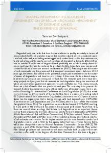
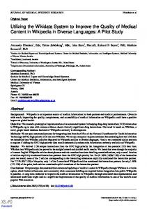
IV.1 A Safety Critical System Verification Example Safety critical systems typically have architectures and design features that are intended to allow safe operation in the presence of system hazards. One of the more significant hazards for flight control actuation systems is the loss of control of an actuator. One such failure mode for a hydraulic actuator is servo valve hardover failure (failure at max output). This failure causes the actuator to move at maximum velocity until it contacts the actuator mechanical travel limits. The result is an aircraft with a control surface fixed at maximum deflection which typically has catastrophic results for the vehicle. Due to the serious effects of the failure, the system design includes functionality to detect and mitigate failures such as this. For this example a test is developed to test the fault response of a rudder actuator to a servo valve hardover failure. For this test, the key system requirements are: 1. The FCAS shall limit surface transients to less 5% of the actuator stroke. 2. The FCAS shall transition a failed surface to the fail-safe mode in less than 250 msec. 3. The FCAS shall annunciate failures to the flight control computer. FCAS = Flight Control Actuation System The system model is developed to include the simulation of key fault conditions. Once the model fidelity is sufficient to represent the system design and the associated fault conditions, a test approach is developed. A set of system input and expected output vectors are defined based on the test approach. For this example, inputs are created to position the actuator at a prescribed position then inject the servo valve fault. The expected outputs are created based on the allowable transient amplitude (< 5% stroke), duration (< 250msec), and the required fault annunciation. The system inputs and expected outputs for this example are shown in Figure 6. Once the test vectors are defined, additional meta-data is associated with the test. Test objectives and a brief description of the test methodology is created and associated with the test vectors. This meta-data aids in review and maintenance of the tests. Links are also created to trace the test to the requirements in the requirements database. The test vectors and associated metadata are stored in a generic data structure to aid in configuration management and test portability. When the test is executed in simulation, the system response is compared to the expected outputs. The simulated test results are displayed and archived automatically using the tool automation features. An example of the simulated test results is shown in Figure 7. This figure shows how the simulated fault transient (amplitude and duration) compare with the upper and lower bounds defined by the requirements.
24th Annual INCOSE International Symposium (IS2015) Seattle, WA, July 10 – 16, 2015
Expected “envelope” for when fault indication should occur
+/- 5% transient amplitude limit
250msec transient duration limit
Injection of servovalve fault
Figure 6. System Input/Expected Output Vectors for Hardover Failure Test
CE1_LR_VotedActPosition 0.1
+/- 5% transient amplitude limit
CE1_LR_VotedActPosition
0.08 0.06 0.04
Simulated transient duration and amplitude
0.02 0
-0.04
Recorded Data Upper Bound Lower Bound
250msec transient duration limit
-0.02
0
1.2
0.5
1
1.5
2 2.5 3 Normalized Results
3.5
4
4.5
5
Figure 7. Results for Simulated Hardover Failure Test
Normalized Value
1 0.8 0.6
Once the test definition is complete, a test procedure is automatically generated using the test 0.4 vectors, test meta-data, and the linked requirements. This is accomplished through a script that 0.2 operates on the test information and formats it through a procedure template. A snapshot of the 0 automated procedure is shown in Figure 8. -0.2 0
0.5
1
1.5
2
2.5 Time (s)
3
3.5
4
4.5
5
24th Annual INCOSE International Symposium (IS2015) Seattle, WA, July 10 – 16, 2015
Test input vectors Traceability Information Expected output vectors Procedure summary, test objectives, and methodology description
Figure 8. Auto-Generated Procedure Excerpts for Hardover Failure Test
When the test is ready to be executed in real-time simulation or the system test lab, the test is converted into a format that is compatible with the test environment. This involves converting the test vectors into a format that can be read and “played back” through the test system. The test is executed by a script that utilizes the test vectors for real-time execution. Data is collected and compared against the expected outputs. An example excerpt from the auto-generated test report is shown in Figure 9.
Figure 9. Auto-Generated Test Report Excerpt for Hardover Failure Test
24th Annual INCOSE International Symposium (IS2015) Seattle, WA, July 10 – 16, 2015
IV.2 Representation Using Formal S*Patterns S*Patterns are configurable S*Models that represent a general class of systems. S*Patterns are constructed to represent a product line or system family. The pattern can be further configured to represent, as an MBSE model, a particular system or product within the family. Both re-usability and configurability are maximized when both the Product System and the Test System of the above example are represented by configurable S*Patterns: The Product System Pattern represents the general class of product systems for the developer enterprise, and this may be specialized to individual product line platforms, and then configured for specific project deliverables. The Test System Pattern represents the general test system (including automated as well as manual aspects) of the developer enterprise, and may be specialized to individual test platforms and further configured to specific project tests.
Figure 10. Product System Pattern and Test System Pattern Each of these S*Patterns consists of generalized configurable models that conform to the S*Metamodel of Figure 1. Figures 11 and 12 are extracts of the ISO15288 model portion of the System of Innovation Pattern, with Figure 12 focused on its Verification Process, itself driven by patterns. Example extracts of the Feature and Interaction portions of these two patterns are summarized in Figure 13. During a project, the applicable System Pattern is configured for the specific product and product test plans. The main input to this configuration is the configuration of the applicable Features from the pattern. Figure 14 illustrates a typical feature configuration process user interface, which can be attached to any third party toolset used as the pattern repository.
24th Annual INCOSE International Symposium (IS2015) Seattle, WA, July 10 – 16, 2015
Logical Architecture View of ISO 15288 Life Cycle Management Processes Project Processes Project Assessment and Control
Project Planning Risk Management
Configuration Management
Decision Management
Information Management
Measurement
Technical Processes Design: Top Level System
Stakeholder Requirements Definition
Realization: Top Level System(s)
Requirements Validation Verification (by Test)
Requirements Analysis
Organizational Project-Enabling Processes
Solution Validation
Transition
Architectural Design
Project Portfolio Management
Integration
Operation
Verification (by Analysis & Simulation)
Infrastructure Management
Maintenance
Disposal
Life Cycle Model Management Realization: Second (and Lower) Level System(s)
Design: Second (and Lower) Level System(s)
Human Resource Management
Stakeholder Requirements Definition
Quality Management
Requirements Validation
Requirements Analysis
Agreement Processes
Architectural Design
Acquisition
Verification (by Analysis & Simulation)
Verification (by Test)
Solution Validation
Integration
Supply Component Level Design, Acquisition, Fabrication
Implementation
Figure 11. From the System of Innovation Pattern: ISO15288 Technical Processes Verification Process Verification by Design Review
Logical Architecture
Requirements Allocations
Review Allocation of Requirements to Physical Architecture
Stakeholder Requirements Alternative Designs
Review Added / Parasitic Behaviors
Review & Verify Requirements Decomposition
Physical Architecture
Review Component Capabilities vs. Requirements
Design Review Results System Failure Analysis
Generate System Failures Model
Design Review Model Failure Analysis Model
Review Physical Architecture Physical Architecture
Verification Plan Verification by Simulation, Test System Concepts
Create System Simulations
Generate Verification Plan
Generate System Test Plan
Verification Model
Perform System Simulations
Create System Characterizati on Plan (DOE, etc.)
Perform System Characterization Tests
Create System Tests
Perform System Tests
Express Margins, Gaps, and Effects in Stakeholder Metrics
Test & Simulation Results
Test Plan
Generate Baseline Document Package
Test & Simulation Results
Test Plan
Baseline Package (Consistent) Baseline Document Package Approve Baseline Document Package
Reusable Pattern Data
Component Capability References
Document Templates
Figure 12. From the System of Innovation Pattern: Verification Process, Pattern-Driven
24th Annual INCOSE International Symposium (IS2015) Seattle, WA, July 10 – 16, 2015
Figure 13. Selected Extracts from Product Pattern and Test System Pattern
24th Annual INCOSE International Symposium (IS2015) Seattle, WA, July 10 – 16, 2015
Figure 14. Configuring the Pattern Features for Specific Product and Test Systems
IV.3 Initial Gains Experienced The application of MBSE patterns to system verification efforts can yield significant improvements in the effectiveness and efficiency of the testing program. The benefits realized through the presented workflow implementation are:
Scalability of test development. The ability to develop and debug tests and the automated scripts independent of the system test lab means that test development can be economically parallelized. Test development in simulation. Verification tests can be developed independent of test hardware. This eliminates the test lab as a potential bottleneck in the development of verification tests. Focus on technical content. Engineers focus on test content and system responses rather than the administrative tasks of generating tests, test procedures, and test reports. This process also eliminates much of the test rework effort because tests can be effectively debugged using the system model. Rapid test development. Tests can be implemented quickly in simulation then converted to run in real-time on the test system in seconds.
The presented application of MBSE patterns as presented in this paper are conservatively expected to reduce integration and test effort by more than 25% for the testing of flight control actuation systems.
IV.4 Future Applications and Extensions Future extensions include the further expansion of the system patterns into the design and modeling of the product system. The goal here is to expand the approach developed and presented here into the analysis and design phases of development. Plans are to demonstrate and mature the patterns for portions of the system and expand the pattern progressively over time while continuing to deliver increased value to current development efforts. One peripheral area to the work presented here is to strengthen the pattern in the area between the product system and the test system to take advantage of the relationships between system requirements and system verification. There are some areas where the pattern could be
24th Annual INCOSE International Symposium (IS2015) Seattle, WA, July 10 – 16, 2015 extended to develop the test cases and content based on the system requirements. In a model-based workflow, this has the potential to automate nearly the entire testing process. Another potential areas for significant gains is to utilize the simulation and analysis capabilities of MBSE along with the S*Patterns to automate simulation and analysis activities. This could help minimize the efforts required for early validation and could provide verification evidence for requirements that are verified by analysis. In many safety-critical applications, a combination of test and analysis is required to verify requirements.
V.
Summary and Conclusions
The application of Pattern-Based Systems Engineering (PBSE) promises to improve the efficiency of system development efforts by leveraging existing intellectual capital in new development efforts. The application of S* Patterns provide a robust framework for creating effective system patterns. The application of MBSE tools and techniques help to realize greater pattern value through workflow automation. This paper presents the application of MBSE system patterns to the testing of flight control actuation systems and the associated benefits. The application of pattern based methods provides significant time and cost savings conservatively estimated at greater than 25%. The presented approach holds promise for testing of similar technological systems. In addition to the reduction in overall testing effort, some additional benefits have also been realized. Greater test program flexibility is realized by decoupling the test creation and debug process from the physical integration facility. This provides spatial and temporal flexibility in the test development effort since the process can occur almost anywhere at any time. As a result, test engineers can start in the lab with mature tests from day one. For larger test development efforts, work can be easily performed in parallel to more effectively meet demanding schedules. These benefits provide additional savings potential through savings in lab facilities and reduction in schedule delays. While significant benefits have been realized from the current MBSE implementation, the potential exists for significant additional gains. By exploiting the relationships embedded in the S*Patterns with MBSE tools and techniques, there is potential to apply automation to much of the system engineering workflow. A few such areas for potential exploration include: Generation of test cases from the pattern based on the requirements for a given system Generation of FMEA/FMECA and fault trees for design analysis and trades for safety critical systems Generation of technical requirements from the pattern Generation of simulation and analysis models from the pattern The further application of S* patterns to similar systems is one of the goals of the INCOSE PBSE Challenge Team.
References Berg, E. 2014. “Affordable Systems Engineering: An Application of Model-Based System Patterns To Consumer Packaged Goods Products, Manufacturing, and Distribution”, INCOSE IW2014 MBSE Workshop.
24th Annual INCOSE International Symposium (IS2015) Seattle, WA, July 10 – 16, 2015 Bradley, J., Hughes, M., and Schindel, W. 2010. “Optimizing Delivery of Global Pharmaceutical Packaging Solutions, Using Systems Engineering Patterns” Proceedings of the INCOSE 2010 International Symposium. Cook, D. 2014. “Electronics Take Off: Real-Time Testing of Modern Actuation Systems at Moog”, dSpace Magazine, Paderborn, Germany. Dove, R., and LaBarge, R. 2014. “Fundamentals of Agile Systems Engineering—Part 1” and “Part 2”, INCOSE IS2014. Dove, R., and Schindel, W., 2015. “Agile Modelling and Modelling Agile Systems” session at INCOSE IW2015 MBSE Workshop, Torrance, CA. INCOSE/OMG MBSE Initiative: Patterns Challenge Team 2013-14 Web Site: http://www.omgwiki.org/MBSE/doku.php?id=mbse:patterns:patterns ISO/IEC 15288 (2015). “Systems Engineering—System Life Cycle Processes”. International Standards Organization. ISO/IEC 26550 (2013) “Software and Systems Engineering—Reference Model for Product Line Engineering and Management”. ISO/IEC42010 (2011) “Systems and Software Engineering—Architecture Description”. Schindel, W. 2005a. “Pattern-Based Systems Engineering: An Extension of Model-Based SE”, INCOSE IS2005 Tutorial TIES 4. -----------. 2005b. “Requirements Statements Are Transfer Functions: An Insight from Model-Based Systems Engineering”, Proceedings of INCOSE 2005 International Symposium. -----------. 2011a. “The Impact of ‘Dark Patterns’ On Uncertainty: Enhancing Adaptability In The Systems World”, in Proc. of INCOSE Great Lakes 2011 Regional Conference on Systems Engineering, Dearborn, MI. -----------. 2011b. “What Is the Smallest Model of a System?”, Proc. of the INCOSE 2011 International Symposium, International Council on Systems Engineering. -----------. 2012. “Introduction to Pattern-Based Systems Engineering (PBSE)”, INCOSE Finger Lakes Chapter Webinar, April, 2012. -----------. 2013. “Interactions: At the Heart of Systems”, INCOSE Great Lakes Regional Conference on Systems Engineering, W. Lafayette, IN. -----------. 2014. “The Difference Between Whole-System Patterns and Component Patterns: Managing Platforms and Domain Systems Using PBSE”, INCOSE 2014 Great Lakes Regional Conference on Systems Engineering, Schaumburg, IL. -----------. 2015a. “Maps or Itineraries? A Systems Engineering Insight from Ancient Navigators”, to appear in Proceedings of the INCOSE 2015 International Symposium, Seattle, WA. -----------. 2015b. “System Life Cycle Trajectories: Tracking Innovation Paths Using System DNA”, to appear in Proceedings of the INCOSE 2015 International Symposium, Seattle, WA. Schindel, W., and Peterson, T. 2013. “Introduction to Pattern-Based Systems Engineering (PBSE): Leveraging MBSE Techniques”, in Proc. of INCOSE 2013 International Symposium, Tutorial. Schindel, W., and Smith, V. 2002. “Results of Applying a Families-of-Systems Approach to Systems Engineering of Product Line Families”, SAE International, Technical Report 2002-01-3086. Schindel, W., Lewis, S., Sherey, J., Sanyal, S. 2015. “Accelerating MBSE Impacts Across the Enterprise: Model-Based S*Patterns”, to appear in Proceedings of the INCOSE 2015 International Symposium, Seattle, WA. Sherey, J. 2006. "Capitalizing on Systems Engineering". INCOSE 2006 International Symposium.
24th Annual INCOSE International Symposium (IS2015) Seattle, WA, July 10 – 16, 2015 Walden, D., Roedler, G., Forsberg, K., Hamelin, R., Shortell, T. 2015. INCOSE Systems Engineering Handbook: A Guide for System Life Cycle Processes and Activities, Version 4, International Council on Systems Engineering.
Biography David Cook is the Systems Chief Engineer for the Moog Aircraft Group. He has over 17 years of experience in the development of safety critical flight control actuation systems. He has been an active advocate and change agent in the introduction MBSE his organization. David is currently a member of the Patterns Challenge Team of the OMG/INCOSE MBSE Initiative.
William D. (Bill) Schindel is president of ICTT System Sciences. His engineering career began in mil/aero systems with IBM Federal Systems, included faculty service at Rose-Hulman Institute of Technology, and founding of three systems enterprises. Bill co-led a 2013 project on the science of Systems of Innovation in the INCOSE System Science Working Group. He co-leads the Patterns Challenge Team of the OMG/INCOSE MBSE Initiative.