rent executions is the introduction of runtime support systems [4], illustrated in the lower ..... The behavior is started by the query control server, which activates the ..... More advanced nodes (like buffers) can be modeled by dedicated building.
Reactive Semantics for Distributed UML Activities Frank Alexander Kraemer and Peter Herrmann Norwegian University of Science and Technology (NTNU), Department of Telematics, N-7491 Trondheim, Norway {kraemer, herrmann}@item.ntnu.no
Abstract. We define a reactive semantics for a subset of UML activities that is suitable as precise design language for reactive software systems. These semantics identify run-to-completion steps for execution on the level of UML activities as so-called activity steps. We show that activities adhering to these semantics and a set of rules lead to event-driven and bounded system specifications that can be implemented automatically by model transformation and executed efficiently using runtime support systems.
1
Introduction
UML 2.0 activities essentially denote in which order certain actions have to be executed to accomplish some task, and are therefore suitable for a wide range of applications. With their revision for the second major version of the UML standard [18], they were considerably enhanced with respect to supporting concurrent flows and hierarchically structured specifications. In the following, we focus on the application of UML activities on the domain of reactive systems. This class of systems, characterized by Pnueli as ones that “ideally never terminate” and that “maintain some interaction with their environment” [19], is especially interesting since with an increasing degree of connectivity of devices and the ubiquity of sensors that provide data, more and more applications fall into this category of systems. In general, these reactive applications and corresponding systems are characterized as follows: – There is a high degree of concurrency in the applications, since typically several connections are active at the same time and events from different sources can occur at any time. – These applications are event-driven, that means they execute their behavior as reactions on events such as incoming signals from other devices, user interface interactions or updated sensor inputs. These characteristics make the development of reactive systems quite demanding, especially with respect to concurrency. Achieving concurrency by processes executing in parallel is complicated, since synchronizations between them are difficult to understand and error-prone. In addition, the number of processes that can be executed efficiently in parallel is limited, in particular on mobile or embedded devices.
UML Activity Transformation, Code Generation Components Runtime Support Systems
Communication Bus
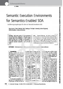
Fig. 1. Execution of components by runtime support systems
Runtime Support Systems. One way to deal with the complexity of concurrent executions is the introduction of runtime support systems [4], illustrated in the lower part of Fig. 1. These systems contain schedulers that control the execution of a component’s behavior by dispatching events. Such events are the arrival of signals from other components, the expiration of timers, or internal signals that arise from local sensor data or interrupts. To be executable by a runtime support system, all application behavior must be expressed as transitions triggered by observable events as defined above. Moreover, communication must be implemented so that the sender is not blocked, for instance via an asynchronous message bus. These properties enable an execution with run-to-completion characteristics. The execution of a run-to-completion step is not preempted, and concludes with a stable state in which the runtime support system waits to dispatch the next observable event. This makes it relatively easy to execute also complex and highly concurrent behavior with very limited resources and a low number of system processes. As a consequence, we generate code for different execution platforms, ranging from resource-constrained embedded systems on Sun SPOTs [16] to systems serving large numbers of users like Telenor’s Connected Objects platform [11]. Activities and Reactive Semantics. Our interest in activities is based on a number of important properties for the development of distributed, reactive systems: In comparison to state machines (that we have used before) they provide a high degree of concurrency by default, since activity flows execute independently from each other. We have also shown that activities can be grouped and abstracted in building blocks [14], which leads to system designs that are built to high proportions from reused solutions. Furthermore, since activities have the concept of partitions, they also describe collaborative behavior, and may encapsulate the behavior of several components that is necessary to fulfill a certain task, illustrated in Fig. 1. We therefore built a tool that takes UML activities and implements them automatically, using first a model transformation to UML components and state machines [13] and then a code generation step. In order to use activities for reactive applications that are to be executed on an event-driven runtime support system as described above, their semantics need to address several issues: – Activities should identify the run-to-completion steps executed by the runtime support system, as well as the observable event triggering a step. – It must be clear on which location a run-to-completion step is performed, i.e., which component is responsible for executing it. 2
– Activities should make communication explicit, i.e., all necessary communication between components must be represented by activity flows. One could argue, of course, that the abstraction level of activities does not need to deal with the same concepts as lower levels. For instance, non-local behavior of activities could be allowed, and communication patterns on the level of component execution could be synthesized automatically (as done for instance by Yamaguchi et al. [25]). However, we want the activities to express communication explicitly, for example to facilitate a security analysis as done in [10]. Furthermore, we want developers working on the level of activities to be still aware of costly operations such as sending to enable efficient solutions. For the same reason we think it is beneficial to be aware of run-to-completion steps, since they form the temporal behavior of specifications. In the following, we describe what we call reactive semantics for activities. Our intention is not to cover all details of the UML standard, but a subset of elements necessary to describe a wide range of reactive applications. We will present UML activities with an example and define some syntactic constraints in Sect. 3. Our semantics are based on run-to-completion steps, which on the activity level we call activity steps. These are defined in Sect. 4. The execution of activities based on activity steps is then described in Sect. 5. Section 6 discusses properties of activities and some additional constraints.
2
Related Work
There exists a variety of approaches that use different techniques to partially define and discuss semantics of UML 2.0 activities. Conrad Bock, one of the authors of the UML standard [18], covers the semantics of activities in a series of articles (starting with [2]) which informally clarify numerous semantic details. In particular, he describes the traverse-to-completion principle [3], according to which tokens pass only when all elements along a path accept the passing. This principle is implied by our semantics due to the definition of run-to-completion steps. Eshuis’ work on model checking activity diagrams [8] defines their semantics by two mappings onto the model checker NuSMV, but in comparison to our work targets towards workflow systems, in which an activity is executed by a central workflow system that coordinates the execution of actions [9]. St¨orrle uses Coloured Petri Nets in [22] to define semantics of some UML activity elements. In [23], St¨ orrle and Hausmann conclude that Petri Nets are probably not suitable to cover more advanced concepts, and point out the difficulty of combining all the various target domains. Barros and Gomez explain the semantics of actions with several input and output pins by “unfolding” these elements into activities with simpler control nodes [1]. Crane and Dingel [5] cover the detailed semantics of some specific UML action types, and describe in [6] a virtual machine for their interpretation. Engels et al. [7] define semantics of activities using Dynamic Meta Modeling (DMM), which is based on graph transformations. Sarstedt and Guttmann [21] use Abstract State Machines (ASMs) for the definitions of activity semantics. This work treats token passing on a very detailed level, removing 3
...
... initial
merge
... decision
... fork
s:SMS
join
accept
create report
operation
ffinal
afinal
queue
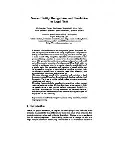
Fig. 2. Node kinds
some restrictions present in other approaches. To execute systems described by activities, they propose the interpretation of models [20]. In contrast to these approaches, we explicitly apply UML activities to the domain of reactive applications as characterized above, with an emphasis on execution mechanisms for runtime support systems. For this case, we found the semantics defined by the approaches mentioned above as not ideal, since they are either too general or target for example business processes, which pose different requirements on communication and synchronization. Therefore, we cannot use them as basis for the construction of executable components. In [12] we earlier described the semantics of collaborations, with their behavior expressed by UML activities, based on temporal logic formulas. We did, however, not introduce the concept of activity steps or discuss the run-to-completion property.
3
UML Activities
The UML standard uses simple text to explain activities, and characterizes their semantics as “Petri-like” [18, p. 324]. Some simple activity graphs can indeed easily mapped to Petri Nets. The mapping of more complex elements of UML activities, however, turns out to be difficult, especially for termination behavior, as pointed out by others [23, 24, 9]. In the following, we will therefore describe the reactive semantics of activities based on the intuitive token flows as found in Petri Nets, but use general state-transition systems in which also groups of tokens of several places can be removed simultaneously. UML Activity Graphs. An activity is a directed graph A with a set of activity nodes VA and a set of activity edges EA . Function kindA ∈ [VA → K] assigns to each node a kind, with K = {initial, merge, decision, fork, join, accept, operation, afinal, ffinal, queue}, as illustrated in Fig. 2. Nodes of kind accept model accept event actions, which in our semantics represent either internal signal receptions or timer expirations. Internal signals are used to represent events from lower layers of a component, such as interrupts or events from user interfaces. Nodes of kind operation represent method calls. There are two kinds of final nodes, activity final nodes (afinal ) that terminate an entire activity (hence removing tokens also from other places and preempting other behaviors), and flow final nodes (ffinal ) that just consume tokens to conclude a flow. An activity has a non-empty set of partitions PA . In general, UML uses partitions to characterize commonalities among nodes. We use them strictly to denote different locations of executions. Thus, a flow crossing partition borders implies communication. For this communication, we assume an asynchronous 4
message bus. This type of communication allows for an increased degree of concurrency, but may introduce interleaving behavior that has to be taken care of by corresponding synchronization. Since this behavior is tightly interleaved with application logic, the delay of messages must be represented in the activity diagrams as well. For this reason, we introduce explicit queue places where activity flows cross partition borders. In Fig. 4, these are nodes q1 to q7 . Function inA ∈ [VA → 2EA ] yields for each node its incoming edges, and function outA ∈ [VA → 2EA ] its outgoing edges. Vice versa, we refer to sourceA (e) to get the source node of an edge, and targetA (e) for its target. We assume that only merge and join nodes have more than one incoming edge, and only decision and fork nodes have more than one outgoing edge. All structural constraints are summarized by the rules in Fig. 3. Function partA ∈ [VA → PA ∪PA ×PA ] assigns partitions to nodes, so that each queue node is mapped to a pair of partitions modeling the transmission of signals between components (PQ). All other nodes are assigned to exactly one partition (PN). Rule E1 ensures that edges do not have the same node as source and target, and P1 ensures that there are no edges between two queues. These cases do not model useful behavior. Rules P2 to P4 ensure that edges do not cross partition borders without a queue node
IN1
v ∈ VA kindA (v) ∈ {initial} |inA (v)| = 0
IN2
v ∈ VA kindA (v) ∈ {decision, fork,
v ∈ VA kindA (v) ∈ {initial,
accept, operation, ffinal, afinal, queue} IN3 |inA (v)| = 1
merge, join, accept, operation} OUT1 |outA (v)| = 1
v ∈ VA
v ∈ VA
kindA (v) ∈ {ffinal, afinal} OUT2 |outA (v)| = 0
kindA (v) ∈ {decision, fork} OUT3 |outA (v)| ≥ 2
q ∈ VA kindA (v) 6= queue partA (v) ∈ PA
PQ
v ∈ VA kindA (q) = queue p1 , p2 ∈ PA partA (q) = hp1 , p2 i p1 6= p2
e ∈ EA sourceA (e) 6= targetA (e)
P1
e ∈ EA kindA (sourceA (e)) = queue kindA (targetA (e)) 6= queue
PN
E1
P2
P3
v ∈ VA kindA (v) ∈ {merge, join} |inA (v)| ≥ 2
e ∈ EA kindA (sourceA (e)) 6= queue kindA (targetA (e)) 6= queue partA (sourceA (e)) = partA (targetA (e))
e ∈ EA kindA (sourceA (e)) 6= queue
e ∈ EA kindA (sourceA (e)) = queue
kindA (targetA (e)) = queue
kindA (targetA (e)) 6= queue
p, q ∈ PA partA (targetA ((e)) = hp, qi partA (source(e)) = p
P4
p, q ∈ PA partA (sourceA ((e)) = hp, qi partA (target(e)) = q
Fig. 3. Rules for incoming and outgoing edges and partitions
5
SMS Query sms gateway register listener
q1
query control
q4
weather server query weather
q5
s: SMS
traffic server
d1 [else]
q2
q6
[cache valid] send SMS
q3
create report
j1
query traffic
q7
Fig. 4. Example activity for an SMS-based query system
in between. (These rules are listed here for completeness. In practice, they are ensured by construction, since queue places are added automatically for edges crossing partitions.) Example. Figure 4 shows a simplified SMS-based query service, in which customers can request weather and traffic information by SMS. The system consists of four components with different tasks, represented by separate activity partitions. The behavior is started by the query control server, which activates the SMS gateway to listen for incoming SMS messages. These are received via accept node s: SMS, emitting one token for each SMS that is forwarded to the query control server. There, a decision is made in d1 whether the cache holds valid traffic and weather data. If yes, a report is created immediately. If data is not available locally, queries are sent towards the weather and traffic servers concurrently. Join j1 then collects their responses, which are used to create the report that is forwarded to the SMS gateway and sent out.
4
Run-to-Completion Steps in Activities: Activity Steps
As explained in the introduction, the execution of components by runtime support systems is based on run-to-completion steps that are triggered by discrete, observable events. On the level of activities, a run-to-completion step is called activity step. With respect to the formal representation of an activity diagram, an activity step is a subgraph a with Va ⊆ VA and Ea ⊆ EA . An activity step covers all nodes and edges that describe behavior executed within one run-tocompletion step. An activity diagram describes with its graph a set of activity steps. The complete set of activity steps for a diagram can be obtained by considering all possible subgraphs ai of A, for which the rules in Fig. 5 hold. – Whenever a node is part of an activity step, then at least one of its incoming or outgoing edges is part of the step as well (rule V). Vice-versa, for each edge part of a step, also its source and target nodes are part of the step (E). 6
– All initial nodes within the same partition release their tokens simultaneously, so that also all other initial nodes within the same partition are part of an activity step (I). – For merge nodes, only one incoming edge is part of an activity step (M). This rules out intricate behavior in which two or more tokens pass the same edge within the same step, as discussed later. – For decision nodes, several activity steps are produced. Each contains the incoming edge, the decision node, and exactly one outgoing edge (D). This means that an activity step executes exactly one branch of a decision. – When a fork is part of an activity step, so are its incoming edge and all outgoing edges, since they are executed in parallel (F). – When a join is part of an activity step, then there is at least one incoming edge part of the step as well (J). – Operations are executed within one run-to-completion step, and thus the incoming and outgoing edge must be part of the same activity step (O). – The sending and the reception at partition borders are part of separate activity steps. Therefore, for each queue place, either the incoming or the outgoing edge is part of the same activity step (Q). – When a node of type initial, accept or queue is part of a step and its outgoing edge as well, then it is triggering the step. Rule T2 ensures that each activity step has at least one such trigger, and rule T1 ensures that is at most one. – Accept nodes are covered by the general rules V and E.
V
v ∈ Va inA (v) ∩ Ea 6= ∅ ∨ outA (v) ∩ Ea 6= ∅ I
M
O
e ∈ Ea source(e) ∈ Va target(e) ∈ Va
i ∈ Va partA (i) = partA (j) kindA (i) = kindA (j) = initial j ∈ Va
m ∈ Va kindA (m) = merge outA (m) ⊆ Ea |inA (m) ∩ Ea | = 1 F
E
D
f ∈ Va kindA (f ) = f ork inA (f ) ⊆ Ea outA (f ) ⊆ Ea
o ∈ Va kindA (o) = operation inA (o) ⊆ Ea outA (o) ⊆ Ea
J
Q
d ∈ Va kindA (d) = decision inA (d) ⊆ Ea |Ea ∩ outA (d)| = 1 j ∈ Va kindA (j) = join inA (j) ∩ Ea 6= ∅
q ∈ Va kindA (q) = queue inA (q) ∩ Ea 6= ∅ ⇔ outA (q) ∩ Ea = ∅
t, u ∈ Va outA (t) ∩ Ea 6= ∅ partA (t) = partA (u) T1 T2
kindA (t) ∈ {initial, accept, queue} kindA (u) ∈ {accept, queue} outA (u) ∩ Ea = ∅ t ∈ Va outA (t) ∩ Ea 6= ∅ kindA (t) ∈ {initial, accept, queue} Fig. 5. Rules for activity step subgraphs
7
a1
q2
q3
a2
d1 [cache valid]
q3
q7
j1
create report
q1
q7
j1
create report
a5
a6
q4
q2 d1
a4
a3
[else]
a7
q5
q3 q6
q4 create report
j1
a9
a11
a10 s: SMS
s: SMS
a8
q5
register listener
a12
q1
q6 q2
query traffic
q7
q3
send SMS
query weather
q5
j1
s: SMS
Fig. 6. Complete set of activity steps for the example
g1 t1
m1
g2 op1
g3
f2
t2 m2
op2
op3
op4
Fig. 7. Illegal subgraphs forbidden by rules
Example. Figure 6 shows the complete set of activity steps that can be produced from the activity in Fig. 4. Steps a1 to a7 are executed within the query control, steps a9 to a11 by the SMS gateway, and a8 and a12 by the weather resp. the traffic server. Some steps are especially interesting: Steps a1 and a5 model the arrival of an SMS by the main server from the SMS gateway. Together they cover the alternative branches introduced by decision node d1 , which either creates the report instantly or starts the query. Steps a2 and a3 represent the arrival of the results from the traffic server (via q7 ). Step a2 covers the situation that the weather information did not yet arrive (and therefore stops at j2 ), while step a3 can fire through j1 since the weather information already arrived.
Inconsistent Diagrams. Figure 7 shows examples of subgraphs that are not valid activity steps. Subgraph g1 results in infinite executions of op1 and is therefore not desired. Subgraph g2 executes op2 twice. While this is not necessarily wrong, we think that this is probably not obvious to and by no means intended by developers, and should be forbidden. Subgraph g3 shows behavior that simply is never reachable. The existence of such invalid subgraphs in a diagram are detected by rule contradictions. The subgraph g1 is illegal since rule O and E would force that both incoming edges of m1 are part of the activity step, which is forbidden by rule M. Similarly, in g2 rule F would contradict rule M. Subgraph g3 has no trigger, contradicting rule T2. The existence of rule contradictions signify inconsistent diagrams that have to be changed. 8
5
Execution Steps and Execution Semantics
We explain next how to model the behavior of a reactive system A specified by a UML activity. Formally, the behavior is expressed as a state transition system in which the states are represented as a placement of tokens on the vertices and edges of the activity. For this reason, we define the type tokensA , 2[VA ∪EA →N] of token mappings assigning each node and edge a natural number. Thus, a token mapping specifies a single system state. Initial State. A specific token mapping initA ∈ tokensA refers to the token mapping of system A in its initial state. This initial mapping assigns one token to each of the vertices of kind initial while all the other nodes and edges are empty, as described by the following rules:
INIT1
v ∈ VA kindA (v) = initial initA (v) = 1 INIT3
INIT2 e ∈ EA initA (e) = 0
v ∈ VA kindA (v) 6= initial initA (v) = 0
Execution Steps. The state transitions are represented by execution steps which correspond to the activity steps and additional information describing the token settings before resp. after executing the step. Formally, we specify the execution step of an activity step represented by a subgraph hVa , Ea i as the quadruple axa = hVa , Ea , prea , posta i. prea ∈ tokensA describes the token setting of A before executing the activity step, and posta ∈ tokensA denotes the token setting afterwards. For an axa to be valid, it must fulfill the following properties: – In general, a token is added to accept and queue nodes when their incoming edge is part of an activity step (IX). – In order to execute, the place representing a trigger must hold a token (AX1). If the trigger place is re-filled within the same step, its token count stays the same (AX3), otherwise it is reduced by one (AX2). – For join nodes, two rules exist: Rule JX1 models the firing of a join when tokens arrive at its incoming edges. As precondition, all edges not part of the activity step must already provide a token each. When the join fires, these tokens are deleted, and the step continues with the outgoing edge of the join. Rule JX2 handles the arrival of tokens at a join when it it not yet complete. As consequence, it adds these arriving tokens but does not continue. – Once a final node is part of an activity step, all tokens within the same partition are removed (see rule AFX1 for tokens on edges and AFX2 for tokens on nodes). The latter rule also removes all tokens within queues towards the partition containing the activity final node. This takes into account that the component implementing the terminated partition is switched off, and any remaining signals towards it are discarded. The additional precondition nofinal(n : 2NA, p : PA ) , ∀f : f ∈ n ∧ partA (f ) = p ⇒ kindA (f ) 6= afinal 9
v ∈ Va kindA (v) ∈ {accept, queue} inA (v) ∩ Ea 6= ∅ outA (v) ∩ Ea = ∅ nofinal(Va , part(v)) IX posta (v) = prea (v) + 1 v ∈ Va v ∈ Va kindA (v) ∈ {initial, accept, queue} AX1
outA (v) ∩ Ea 6= ∅ prea (v) > 0
kindA (v) ∈ {initial, accept, queue} AX2
outA (v) ∩ Ea 6= ∅ inA (v) ∩ Ea = ∅ posta (v) = prea (v) − 1
v ∈ Va kindA (v) = accept inA (v) ∩ Ea 6= ∅ AX3
outA (v) ∩ Ea 6= ∅ nofinal(Va , part(v)) posta (v) = prea (v) v ∈ Va kindA (v) = join es = inA (v) ∩ Ea
∀e ∈ inA (v) \ es : prea (e) > 0 nofinal(Va , part(v)) JX1 outA (v) ⊆ Ea ∀e ∈ inA (v) \ es : posta (e) = prea (e) − 1 v ∈ Va kindA (v) = join es = inA (v) ∩ Ea ∃e ∈ inA (v) \ es : prea (e) = 0 nofinal(Va , part(v)) JX2 outA (v) ∩ Ea = ∅ ∀e ∈ es : posta (e) = prea (e) + 1 e ∈ E A f ∈ Va
f ∈ Va v ∈ VA kindA (f ) = afinal
kindA (f ) = afinal part(f ) = part(targetA (e)) AFX1 posta (e) = 0
part(v) = part(f ) AFX2
∨ part(v) = h , part(f )i posta (v) = 0
Fig. 8. Execution rules for activity steps
added to rules IX, AX3, JX1 and JX2 ensures that these rules only apply if no activity final node is part of the activity step, to give rules AFX1 and AFX2 priority. – All vertices and edges of A not mentioned by one of the rules explicitly do not change their token setting in the execution step axa . System Description. We define the set AXA as the set of execution steps axa each following the rules mentioned above. This set contains execution steps that are not reachable. We define the set of reachable execution steps RAXA ⊆ AXA by means of the following two rules: a ∈ AXA ∀v ∈ VA : kindA (v) = initial ⇔ prea (v) = 1 ∀v ∈ VA : kindA (v) 6= initial ⇔ prea (v) = 0 ∀e ∈ EA : prea (e) = 0 R1 a ∈ RAXA a, b ∈ AXA ∀v ∈ VA : prea (v) = postb (v) R2
∀e ∈ EA : prea (e) = postb (e) b ∈ RAXA a ∈ RAXA 10
The rules define recursively that the reachable execution steps a are those containing a token setting prea reachable by a final trace of execution steps from the initial token setting. The behavior of system SysA is then defined by the state transition system expressed by the quadruple SysA , hVA , EA , initA , RAXA i.
6
Properties of Activities with Reactive Semantics
In the following, we will discuss the properties of activities with reactive semantics. The properties in Sect. 6.2 and 6.3 require additional behavioral invariants, that is, they only hold for a subset of activities. We will assure these by additional rules that have to hold for any a ∈ RAXA . In practice, these rules are verified by model checking, as discussed in [17]. 6.1
Event-Driven Execution and Run-to-Completion
As described in Sect. 1, the events observable by a runtime support system are the expiration of timers, the arrival of internal signals, or the arrival of signals from other components. On the activity level, these events are modeled by accept event actions and activity flows that cross partition borders via queues. The initial startup of a component is also an event, modeled by initial nodes in activities. Due to rules T1 and T2, we ensure that each execution step declares exactly one such trigger, meaning that activity steps started by an observable event. Furthermore, tokens may be only placed according to two properties: (i) Tokens may rest on a vertex only if it is of kind initial, accept, or queue. (ii) Tokens may rest on edges if they lead to a join node, but only if the join is not yet complete, i.e., there is one incoming edge that cannot offer a token. Property (i) ensures that tokens only wait in places that imply waiting for an observable event. In initial nodes, this is the start of the system, in queues the arrival of the signal and for accept nodes the expiration of a timer or the arrival of an internal signal, resp. Property (ii) is more subtile. Tokens may wait on edges preceding join nodes. But since join nodes do not declare any observable events, tokens may only rest before a join if the join is not yet complete. The join fires through within the same step once the last missing token arrives. Hence, a token stored in an incomplete join implies waiting for another observable event. Formally, (i) and (ii) can be expressed as P , E1 ∧ E2 ∧ E3 ∧ E4 , with E1 , ∀v ∈ VA : kind(v) ∈ {initial, accept, queue} ∨ initA (v) = 0 E2 , ∀e ∈ EA : kind(targetA (e)) 6= join ∧ initA (e) = 0 ∨ ∃f ∈ EA : f ∈ in(targetA (e)) ∧ initA (f ) = 0 E3 , ∀v ∈ VA ∀a ∈ RASA : kind(v) ∈ {initial, accept, queue} ∨ posta (v) = 0 E4 , ∀e ∈ EA ∀a ∈ RASA : kind(targetA (e)) 6= join ∧ posta (e) = 0 ∨ ∃f ∈ EA : f ∈ in(targetA (e)) ∧ posta (f ) = 0 11
E1 and E2 describe that (i) and (ii) hold in the initial state of the system while E3 and E4 guarantee that all execution steps a ∈ RASA preserve them as well. E1 holds due to rules INIT1 and INIT2 and E2 holds due to rule INIT3. To prove E3 , we consider the rules in Fig. 8. The only rule describing that the token setting of a vertex v after executing an execution step a can be greater than before (i.e., posta (v) > prea (v)) is IX. But according to the second premise of the rule, the token setting may only be increased for tokens of kind accept and queue. Thus, if a vertex of a type other than initial, accept or queue has no token placed on it before the execution of the execution step, it will carry none afterwards as well. In consequence, it will never carry a token at all. The proof of E4 is quite similar. The only rule in Fig. 8 modeling an increase of a token setting on an edge in an execution step is JX2. Yet it does not allow the placement of new tokens on edges leading to a vertex not being of kind join as expressed by the third premise. So, the first disjunct of E4 holds and in all system states only edges into a join may have tokens at all. Further, the forth premise of the rule states that there is an edge leading into the join node to which no token is assigned. As this edge is not an element of the edges receiving new tokens (expressed by set es), it will not carry a token after firing the execution step. Thus, the second disjunct of E4 holds as well and a join node will always have an incoming edge without a token placed on it. 6.2
Realizability and Distribution
To be executable as one run-to-completion step, an activity step must only have direct local effects, and only depend on data that is available locally. Rules Q and P1 to P4 split up activity steps at partition borders. Within one activity step, all nodes except queues are therefore part of the same partition. For flows crossing partition borders, we take the unavoidable communication delay into account by explicit queue nodes, so that they can be implemented using some communication middleware. For some nodes, the general semantics of UML describe also non-local dependencies, that motivate some further constraints: – As an extension to standard UML, we assume that variables, like activity nodes, are assigned to partitions. Guards and actions are only allowed to access variables within their own partition. – Initial nodes are started simultaneously, but only those within the same partition. This is already ensured by rule I. – In standard UML, accept event actions without incoming edge denote that they are activated with the surrounding activity. Instead, we require these actions to have an incoming edge (rule IN3), to model activation explicitly. – Activity final nodes terminate in standard UML the entire activity. With the reactive semantics, they only remove tokens within the same partition (rules AFX1 and AFX2). Since messages towards a terminated partition are discarded, queues towards a terminated partition are emptied as well. To comply with the general semantics of activity nodes in which an activity final node terminates the behavior in all partitions, the other partitions must not be 12
TERM1
TERM2 AB
f ∈ Va kindA (f ) = afinal kindA (v) = accept partA (v) 6= partA (f ) prea (v) = posta (v) = 0 f ∈ Va q ∈ VA kindA (f ) = afinal kindA (q) = queue partA (q) 6= h , f i prea (q) = posta (q) = 0
v ∈ Va kindA (v) = accept posta (v) ≤ 1 QB
JB
v ∈ Va kindA (v) = join e ∈ inA (v) posta (e) ≤ 1
v ∈ Va kindA (v) = queue posta (v) ≤ maxqueue
Fig. 9. Additional rules for activities
able to execute any further activity steps. This is ensured by the additional rules TERM1 and TERM2. The former states that whenever an activity final node is reached, there must not be any token in accept nodes of other partitions. The latter states that all queues not targeting the terminated partition must be empty as well. Since tokens offered to join nodes cannot trigger any behavior on their own, they do not have to be removed upon termination. 6.3
Boundedness
Since the number of places needed to describe an activity is limited, the state space implied by a specification is finite if (and only if) each place only contains a bounded number of tokens, i.e., |tokensA (x) < N |, with N as a finite boundary. Rules IX and JX2 are the only rules increasing token places. – Accept nodes are either enabled or disabled, represented by one or zero tokens on their corresponding place. We found that adding more than one token in an accept node is in most cases unintended and an indicator of a design flaw. We therefore rule out such behavior by rule AB. – Places before join nodes can hold many tokens which implies buffering of data or control flow. We found that this makes activities harder to understand, without adding any expressiveness for reactive systems; we rather recommend to use explicit building blocks to describe buffering, as in [15] and rule out behaviors in which tokens accumulate before joins by rule JB. – Queues between partitions need to be bounded as well. That means, they must not exceed a certain value maxqueue ∈ N, expressed by rule QB. If the boundedness rules hold, the set of reachable execution steps RASA will be finite as it is lower or equal to the product of run-to-completion steps times possible token markings following the boundedness constraints.
7
Concluding Remarks
We described a reactive semantics for UML activities, in which each execution step is triggered by an observable event. This is motivated by existing mechanisms present in runtime support systems for efficient but nevertheless simple 13
scheduling and execution of highly concurrent behavior. As a consequence of the reactive semantics, the components produced by our model transformation [13] from activities have the same efficiency as if they would have been produced manually by an experienced designer, i.e., do not contain any overhead for token control, and it is not visible that they were generated from UML activities. We have implemented comprehensive tool support with Arctis [17], a set of Eclipse plug-ins. It enables editing, analyzing and automatically implementing activity-based specifications. The syntactical rules from Fig. 3 are ensured by the editor, highlighting erroneous parts of the graph. Similarly, the tool can produce all activity steps implied by a diagram, using the rules from Fig. 5. Rule contradictions that signify illegal diagrams are detected and explained to the user. The steps are used to animate diagrams, which makes it also easy for beginners to get familiar with the reactive semantics. Finally, the additional rules for sound behavior in Fig. 9 are verified by model checking [17]. Our tool also supports data in activities, which we did not treat here. Our experience from implementing data shows that their semantics can be covered by extending the semantics for control flows in a straight-forward way. Operations with more than one incoming flow, for instance, can be modeled similar to join nodes. More advanced nodes (like buffers) can be modeled by dedicated building blocks, as shown in [15]. Concerning the expressiveness of the chosen reactive semantics we point to numerous case studies (summarized in [14]) that exemplify their application in various domains. With an abstraction mechanism described in [14] such solutions can also be encapsulated by dedicated building blocks from which large system designs can be produced in a scalable manner.
References 1. J. P. Barros and L. Gomes. Actions as Activities and Activities as Petri Nets. In Workshop on Critical Systems Development with UML, October 2003. 2. C. Bock. UML 2 Activity and Action Models. Journal of Object Technology, 2(4):pp. 43–53, July-August 2003. 3. C. Bock. UML 2 Activity and Action Models, Part 4: Object Nodes. Journal of Object Technology, 3(1):pp. 27–41, January-February 2004. 4. R. Bræk and Ø. Haugen. Engineering Real Time Systems: An Object-Oriented Methodology Using SDL. The BCS Practitioner Series. Prentice Hall, 1993. 5. M. L. Crane and J. Dingel. Towards a Formal Account of a Foundational Subset for Executable UML Models. In MoDELS ’08: Proceedings of the 11th Int. Conf. on Model Driven Engineering Languages and Systems, Springer, 2008. 6. M. L. Crane and J. Dingel. Towards a UML Virtual Machine: Implementing an Interpreter for UML 2 Actions and Activities. CASCON ’08: Proc. of the 2008 conf. of the center for advanced studies on collaborative research, ACM, 2008. 7. G. Engels, C. Soltenborn, and H. Wehrheim. Analysis of UML Activities Using Dynamic Meta Modeling. In FMOODS, LNCS 4468, pages 76–90. Springer, 2007. 8. R. Eshuis. Symbolic Model Checking of UML Activity Diagrams. ACM Transactions on Software Engineering and Methodology, 15(1):1–38, 2006. 9. R. Eshuis and R. Wieringa. Comparing Petri Net and Activity Diagram Variants for Workflow Modelling - A Quest for Reactive Petri Nets. In Petri Net Technology for Communication-Based Systems, LNCS 2472, pages 321–351. Springer, 2003.
14
10. L. A. Gunawan, P. Herrmann, and F. A. Kraemer. Towards the Integration of Security Aspects into System Development using Collaboration-Oriented Models. In Proc. of the 2009 Int. Conf. on Security Technology (SecTech 2009), Communications in Computer and Information Science, v. 58, Springer, 2009. 11. A. Herstad, E. Nersveen, H. Samset, A. Storsveen, S. Svaet, and K. E. Husa. Connected Objects: Building a Service Platform for M2M. In Beyond the Bit Pipe. Proccedings of the 13th ICIN Conference, 2009. 12. F. A. Kraemer and P. Herrmann. Formalizing Collaboration-Oriented Service Specifications using Temporal Logic. In Networking and Electronic Commerce Research Conference 2007 (NAEC 2007), pages 194–220, USA, October 2007. ATSMA Inc. 13. F. A. Kraemer and P. Herrmann. Transforming Collaborative Service Specifications into Efficiently Executable State Machines. In Proceedings of the 6th Int. Workshop on Graph Transformation and Visual Modeling Techniques (GT-VMT 2007), volume 7 of Electronic Communications of the EASST. EASST, 2007. 14. F. A. Kraemer and P. Herrmann. Automated Encapsulation of UML Activities for Incremental Development and Verification. In Proc. of the 12th Int. Conf. on Model Driven Engineering, Languages and Systems (Models), LNCS 5795, Springer, 2009. 15. F. A. Kraemer, H. Samset, and R. Bræk. An Automated Method for Web Service Orchestration based on Reusable Building Blocks. In Proc. of the 7th Int. IEEE Conf. on Web Services (ICWS). IEEE Computer Society, July 2009. 16. F. A. Kraemer, V. Sl˚ atten, and P. Herrmann. Model-Driven Construction of Embedded Applications based on Reusable Building Blocks – An Example. In A. Bilgic, R. Gotzhein, and R. Reed, editors, SDL 2009, volume 5719 of Lecture Notes in Computer Science, pages 1–18. Springer-Verlag Berlin Heidelberg, 2009. 17. F. A. Kraemer, V. Sl˚ atten, and P. Herrmann. Tool Support for the Rapid Composition, Analysis and Implementation of Reactive Services. Journal of Systems and Software, 82(12):2068–2080, December 2009. 18. Object Management Group. Unified Modeling Language: Superstructure, version 2.2, February 2009. formal/2009-02-02. 19. A. Pnueli. Applications of Temporal Logic to the Specification and Verification of Reactive Systems: A Survey of Current Trends. Current Trends in Concurrency. Overviews and Tutorials, pages 510–584, 1986. 20. S. Sarstedt, D. Gessenharter, J. Kohlmeyer, A. Raschke, and M. Schneiderhan. ActiveChartsIDE: An Integrated Software Development Environment Comprising a Component for Simulating UML 2 Activity Charts. In Proceedings of the 2005 European Simulation and Modelling Conference (ESM’05), pages 66–73, 2005. 21. S. Sarstedt and W. Guttmann. An ASM Semantics of Token Flow in UML 2 Activity Diagrams. Ershov Memorial Conference, LNCS 4378, pages 349–362. Springer, 2006. 22. H. St¨ orrle. Semantics and Verification of Data Flow in UML 2.0 Activities. In Electronic Notes in Theoretical Computer Science, volume 127, 2005. 23. H. St¨ orrle and J. H. Hausmann. Towards a Formal Semantics of UML 2.0 Activities. In P. Liggesmeyer, K. Pohl, and M. Goedicke, editors, Software Engineering, volume 64 of LNI, pages 117–128. GI, 2005. 24. W. M. P. van der Aalst and T. A. H. M. Hofstede. Workflow Patterns: On the Expressive Power of (Petri-net-based) Workflow Languages. In K. Jensen, editor, Proceedings of the Fourth Workshop on the Practical Use of Coloured Petri Nets and CPN Tools (CPN 2002), volume 560 of DAIMI, pages 1–20, August 2002. 25. H. Yamaguchi, K. El-Fakih, G. von Bochmann, and T. Higashino. Protocol Synthesis and Re-Synthesis with Optimal Allocation of Resources based on Extended Petri Nets. Distrib. Comput., 16(1):21–35, 2003.
15