sufficient energy dissipation to achieve a satisfactory seismic response, Seo and Sause (2005) recommend βE ..... CMS-0402490 NEES Consortium Operation.
VALIDATING PERFORMANCE OF SELF-CENTERING STEEL FRAME SYSTEMS USING HYBRID SIMULATION Richard Sause1, James M. Ricles1, Ying-Cheng Lin1, Choung-Yeol Seo1, David A. Roke1, N. Brent Chancellor1, and Nathaniel Gonner1 ABSTRACT Innovative seismic-resistant self-centering (SC) moment-resisting frames (SC-MRFs) and selfcentering concentrically-braced frames (SC-CBFs) are being developed. The beams of an SCMRF are post-tensioned to the columns using high strength post-tensioning (PT) strands. The SC-MRF connection behavior is characterized by gap opening and closing at the beam-column interface. The SC-CBF has beams, columns, and braces in a conventional arrangement, with column base details that permit the columns to uplift at the foundation. Gravity loads and posttensioning forces resist column uplift and provide a restoring force after uplift. The SC steel frames are designed to meet two seismic performance objectives, namely, (1) no damage or residual drift under the Design Basis Earthquake (DBE), leading to immediate occupancy performance after the DBE, and (2) collapse prevention performance under the Maximum Considered Earthquake. A 7x7-bay, 4-story SC-MRF prototype building and a 6x6-bay, 4-story SC-CBF prototype building were designed for a stiff soil site in the Los Angeles area using performance-based design procedures with these performance objectives. A 0.6-scale model of a 2-bay SC-MRF from the prototype building was evaluated using the hybrid simulation method. Similar simulations on a 0.6-scale model 1-bay SC-CBF are in progress. Experimental results of earthquake simulations on these SC frames are being used to assess the performance-based design procedures. INTRODUCTION Conventional moment-resisting frames (MRFs) and concentrically-braced frames (CBFs) soften and dissipate energy under the Design Basis Earthquake by developing yielding and associated damage in critical regions of the main structural members. This damage can result in significant residual drift after the earthquake. To avoid this damage and residual drift in MRFs, posttensioned beam-column connections for self-centering moment-resisting frames (SC-MRFs) were developed by Ricles et al. [2001] and others. The behavior of these connections is characterized by gap opening and closing at the beam-column interface. Energy dissipation occurs in special devices designed for the beam-column connection regions. Together, the PT strands and the energy dissipation devices provide the flexural resistance of the connections. Recently, Roke et al. (2006) and Sause et al. (2006) introduced the self-centering concentricallybraced frame (SC-CBF), to reduce the damage and residual drift of CBFs. An SC-CBF has beams, columns, and braces in a conventional arrangement, with column base details that permit the columns to uplift at the foundation. Gravity loads and post-tensioning (PT) forces resist column uplift and provide a restoring force after uplift. This paper presents an experimental study on an SC-MRF which uses beam web friction devices (WFDs) as energy dissipation devices. The WFDs are positioned on the beam webs to avoid 1
ATLSS Engineering Research Center, Lehigh University, Bethlehem, PA 18015 1
interference with the floor slab and are attached to the columns at the beam-column interface. Using a performance based design (PBD) approach the SC-MRF is designed to remain damagefree under the Design Basis Earthquake (DBE) to enable immediate occupancy, while also achieving the collapse prevention performance level under the Maximum Considered Earthquake (MCE). Experimental results from hybrid simulations of the SC-MRF under earthquake loading conditions are presented in the paper and are used to assess the design procedure. The paper also summarizes a PBD procedure for SC-CBFs. A 0.6-scale SC-CBF test structure that was developed using the PBD procedure is outlined. An experimental program including hybrid simulations on this test structure is summarized. These experiments are ongoing and the results will be used to assess the PBD procedure for SC-CBFs. SC-MRF OVERVIEW Figure 1(a) shows an SC-MRF with PT strands and WFDs. The PT strands run across multiple bays. The WFD, shown in Figure 1(b), includes two “friction” channels welded to the column flange. Brass plates are sandwiched between the friction channels and beam to provide reliable friction conditions. Normal force on the friction surface between the channels and beam is provided by friction bolts shown in Figure 1(b). The friction channels are welded to the column flange after the friction bolts are tightened. The friction channel shape was selected to reduce the effect of weld shrinkage on the friction surface normal force. Slotted holes are used in the beam web to accommodate the travel of the friction bolts during the gap opening and closing of the connection (discussed later). The shim plates shown in Figure 1(b) are welded to the column flange to provide good contact surfaces for the beam flanges. Reinforcing plates are welded on the outside faces of the beam flanges to avoid excessive yielding in the beam flanges. The conceptual moment-relative rotation (M-θr) behavior of the connection shown in Figure 1(b) is shown in Figure 1(c). From event 0 to 2, the connection has stiffness similar to that of a conventional welded moment connection. After the connection moment M reaches the imminent gap opening moment at event 2 (MIGO), the beam tension flange loses contact with the shim plate at the column face and gap opening occurs. MIGO is the sum of the decompression moment Md due to the initial PT force (event 1) and the moment MFf due to friction in the WFD. After MIGO is exceeded, M increases with increases in the PT strand force due to gap opening (event 2 to 3). Excessive gap opening will eventually yield the PT strands at event 4. During unloading between events 3 and 5, θr remains constant but M decreases by 2MFf due to the reversal in direction of the WFD friction force. Continued unloading between events 5 and 6 reduces θr to zero as the beam tension flange comes in contact with the shim plate at the column face. Further unloading (between events 6 and 7) decreases M to zero as the beam tension flange fully compresses against the shim plate. Similar behavior occurs under load reversal. After MIGO is reached, M = P d2 + Ff r, where P is the axial force in the beam, Ff is the WFD friction force resultant, d2 is the distance from the beam cross section centroid to the center of rotation (COR) of the connection, and r is the distance from Ff to the COR. The COR is at the point of contact of the beam compression flange with the column. Note that P = T+ Ffd where T is the PT force and Ffd reflects the effects of interaction between the SC-MRF and floor system (e.g., floor diaphragm forces) (Garlock et al. 2005). T depends on the initial PT force, To, and the strand elongation due to θr. 2
Fig. 1. (a) 2-bay SC-MRF with PT strands and WFDs, (b) Connection details, and (c) Conceptual M-θr behavior of connection. PERFORMANCE-BASED DESIGN OF SC-MRFS The performance-based design (PBD) procedure proposed for SC-MRFs [Garlock et al. 2005] considers two levels of seismic hazard, namely the DBE and MCE. The DBE has two-thirds the intensity of the MCE [FEMA 2000] and an approximate 10% probability of being exceeded in 50 years. The MCE has a 2% probability of being exceeded in 50 years. Under the DBE, an SCMRF is designed to achieve immediate occupancy (IO) performance [FEMA 2000], with limited structural and nonstructural damage. Under the MCE, an SC-MRF is designed to achieve collapse prevention (CP) performance [FEMA 2000]. The performance objectives and limit states of an SC-MRF with WFDs are shown in a conceptual base shear-roof drift (V- θroof) response in Figure 2. Before the IO performance limit, connection decompression and yielding at the column bases of the SC-MRF are permitted to occur. Panel zone yielding, beam web yielding, and a beam flange strain greater than twice the yield strain (i.e., 2εy) are permitted to occur between the IO and CP performance limits. Before the CP limit, PT strand yielding, beam web buckling, Fig. 2. SC-MRF performance-based design. and excessive story drift are not permitted. The PBD procedure permits the use of an equivalent lateral force analysis of the SC-MRF, using an analysis model with rigid beam-column connections that is subjected to the design forces defined in ASCE7-05 [2005] with a response modification factor R equal to 8. The design moment Mdes from this analysis is used to establish an initial value of MIGO approximately equal to 0.95Mdes. The effective energy dissipation ratio of the SC-MRF connections, βE = MFf /MIGO, is used to establish the proportion of MIGO provided by Mdes. To provide the SC-MRF with 3
sufficient energy dissipation to achieve a satisfactory seismic response, Seo and Sause (2005) recommend βE ≥ 0.25, however to enable connection re-centering, βE ≤ 0.40. The PBD procedure includes numerous steps to control the limit states shown in Figure 2. In this procedure, estimates of the θr demand under the DBE and MCE are critical for determining whether these limit states are reached. The details of the PBD procedure are given in Garlock et al. [2005]. SC-MRF EXPERIMENTAL PROGRAM The PBD procedure described above was used to design SC-MRFs for the 7x7-bay 4-story prototype building shown in plan in Figure 3(a). The building is located on a stiff soil site in the Los Angeles area. The perimeter frames include SC-MRFs. Each perimeter frame has two 2-bay SC-MRFs with WFDs. Figure 3(a) shows the floor diaphragm is attached to one bay of each SCMRF to avoid restraining gap opening of the SC-MRF connections. The test frame for the experimental program is a 0.6-scale model of one SC-MRF from the prototype building, as shown in Figure 3(b). The test frame has A992 steel members which were scaled down from the prototype SC-MRF. Table 1 gives the design demands for roof drift (θroof), story drift (θs), and connection relative rotation (θr) at the DBE and MCE levels. The initial PT forces To, shown in Figure 3(b), are less than 45% of strand ultimate strength (Tu). Design values of βE are shown in Figure 3(b). During the experiments, lateral force is applied at each floor level by hydraulic actuators through a simulated floor diaphragm attached near the middle of the North-bay beam shown in Figure 3(b). The hybrid simulation method was used for earthquake simulations. In these simulations, the test frame was the experimental substructure, while the gravity load bearing system, gravity loads, and the seismic mass tributary to the test frame were included in the analytical substructure. The hybrid simulation used 2% damping in the 1st mode and 5% damping in the 3rd mode. The explicit unconditionally stable CR integration algorithm by Chen and Ricles (2008) was used to solve the equations of motion. Table 1. Design demands (in radians) θroof,DBE
θs,DBE
θr,DBE
θroof,MCE
θs,MCE
θr,MCE
0.026
0.039
0.031
0.039
0.059
0.047
(a)
(b)
Fig. 3. Schematic of (a) Plan of prototype, and (b) Elevation of 0.6-scale 4-story 2-bay SCMRF test frame (note: 1′ = 1ft. = 305mm; 1″= 1in. = 25.4mm). 4
Table 2 shows the hybrid simulation matrix. Ground motions at the frequently occurring earthquake (FOE), DBE, and MCE levels were used. Three different DBE level ground motion records were used and are denoted DBE-1, DBE-2 and DBE-3. Each of these records was one of a pair of recorded orthogonal components of horizontal ground acceleration. To develop a set of DBE-level ground motions, fifteen such pairs were selected from earthquake ground motion data bases, and scaled so that the geometric mean of the spectral accelerations (Sa) of the record pair was equal to the Sa value at a period of 1.5 seconds in the uniform hazard spectrum (UHS) for the prototype building site in the Los Angeles area. To use these records for the hybrid simulations, the time step for the records were scaled by (0.6)1/2 (=0.77), where 0.6 is the scale factor of the test frame. Table 2. Test matrix of hybrid simulations
FOE-1 FOE-2 DBE-1 DBE-2 DBE-3 MCEs Aftershock
Description
Record
Scale Factor
-0.70 -1.41 H-ECC002 0.94 SJTE315 -2.23 LOS000 1.18 Varied w/ tests SJTE315 -2.23
1979 Imperial Valley
H-CXO225
1979 Imperial Valley 1989 Loma Prieta 1994 Northridge 1994 Northridge 1989 Loma Prieta
Method Hybrid simulation
Tests
Sa (g)
2 The selected records, DBE-1, DBE-3 response spectrum DBE-2 and DBE-3, cause a 1.5 maximum story drift that is UHS for 10% exceedance probability in 50 years approximately one-standard DBE-2 response spectrum 1 deviation lower than, similar to, DBE design spectrum (ASCE7-05) and one-standard deviation higher 0.5 than, respectively, the mean maximum story drift from DBE-1 response spectrum nonlinear dynamic analyses of the 0.5 1 1.16 1.5 2 2.5 test frame for the set of DBE-level Period (sec.) ground motion records. Figure 4 Fig. 4. Pseudo-acceleration response spectra. compares the DBE design spectrum based on ASCE7-05 [2005], the uniform hazard spectrum, UHS, which has a 10% probability of exceedance in 50 years at the prototype building site, and the individual response spectra for the DBE-1, DBE-2 and DBE-3 records. In this figure, all periods are scaled by the time scale factor of (0.6)1/2 (=0.77). It should be noted that Sa for the DBE design spectrum at the period of 1.16 sec (which is approximately the fundamental period of the test frame) is slightly higher than the corresponding Sa of the UHS (i.e., 0.4g vs. 0.35g), because the DBE design spectrum is defined to have two-thirds the intensity of the MCE design spectrum [FEMA 2000], and is not directly equal to the UHS which has 10% probability of exceedance in 50 years. The Sa of the individual response spectra for DBE-1, DBE-2, and DBE-3 at 1.16 sec. vary from 0.32g to 0.4g because each record was not scaled individually to the target Sa value, rather, each record pair was scaled by a single scale factor so that the geometric mean of Sa for the record pair equaled the target Sa value (0.35g).
5
SC-MRF EXPERIMENTAL RESULTS Floor displacement time histories from the DBE-2 hybrid simulation are shown in Figure 5(a). The residual story drifts of the test frame are given in Table 3 and were obtained by dividing the difference in residual displacements of adjacent floors by the story height. Table 3 shows the maximum residual story drift θs resid after DBE-2 is 0.00061 radians, which demonstrates the selfcentering capability of the SC-MRF. Table 3 shows other results from the DBE-2 simulation, and includes the maximum story drift θs max, maximum relative rotation θr max, maximum PT force Tmax and loss of PT force during the simulated earthquake, ΔT, normalized by the strand tensile strength Tu. The maximum θs max is 2.9% radians, which is less than the expected design demand of 3.9% radians (Table 1) for the DBE. The maximum θr max is 2.7% radians, which is less than the expected design demand of 3.1% radians for the DBE. The maximum PT force in the DBE-2 simulation was 0.6Tu. No yielding occurred in the PT strands. The PT force decreased slightly due to seating of the PT strand anchorage, and ΔT is less than 1% of Tu. 10 Flr. Disl. (in.)
(a)
1F 2F 3F RF
5 0 -5 0
5
10
15
20
20 Flr. Disl. (in.)
(b)
1F 2F 3F RF
10 0 -10 0
5
10 Time (sec.)
15
20
Fig. 5. Floor displacements time histories from (a) DBE-2, and (b) DBE-3. Table 4. Simulation results from DBE-2 and DBE-3
DBE-3
DBE-2
Level 4 3 2 1 4 3 2 1
θs resid (rad.) 0.00045 0.00061 0.00035 0.00014 0.00008 0.00023 0.00063 0.00074
θs max (rad.) 0.029 0.025 0.014 0.008 0.039 0.035 0.035 0.021
6
θr max (rad.) 0.027 0.024 0.014 0.005 0.038 0.034 0.031 0.025
Tmax/Tu (%) 60 54 51 46 65 60 61 59
ΔT,/Tu (%) -0.5 -0.4 -0.0 -0.0 -0.7 -0.7 -1.3 -1.0
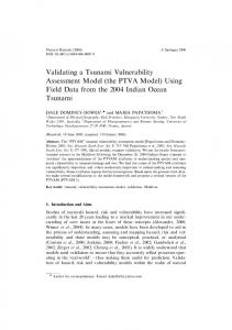
M (kip-in)
Figure 5(b) shows floor displacement time histories from DBE-3. The maximum θs resid after DBE-3 is 0.00074 radians, which further demonstrates the self-centering capability of the SCMRF. The 1st story residual drift from the DBE-3 simulation is larger than that from the DBE-2 simulation due to yielding in the columns at the ground level. Table 3 shows the maximum θs max is 3.9% radians, which equals the design demand for the DBE (Table 1). The maximum θr max is 3.8% radians, which is slightly larger than the design demand of 3.1% radians for the DBE. The maximum PT force in the DBE-3 simulation was 0.65Tu. No yielding occurred in the PT strands. ΔT is less than 1.5% of Tu. The self-centering behavior of the SC-MRF beam-column connections is illustrated by the typical M-θr response from the DBE-3 simulation for the Northend connection of the 3rd floor South-bay beam (denoted 3FSN), shown in Figure 6. After gap opening, the stiffness differs in the positive and negative moment directions due to the floor diaphragm force (i.e., the lateral force from the actuator) acting on the North-bay beam. When 3000 the test frame is loaded to the North by the floor diaphragm, a tension axial 1500 force is imposed on the South-bay beam. When test frame is loaded to the South, a compression axial force is 0 imposed on the South-bay beam. Therefore, the axial force in the South -1500 bay is different for the North and South loading directions. βE estimated -3000 -4 -2 0 2 4 from the DBE-3 simulation results is θ (rad.) r around 30%. Overall, the SC-MRF Fig. 6. M vs. θ for 3FSN connection from DBE-3. r achieved the performance objectives. SC-CBF OVERVIEW Steel concentrically-braced frame (CBF) systems are stiff and economical earthquake-resistant steel frame systems with limited ductility capacity and a tendency to accumulate residual drift during an earthquake. To increase the ductility and reduce the residual drift of CBFs, the selfcentering concentrically-braced frame (SC-CBF) system, shown schematically in Figure 7(a), is being developed. The system has beams, columns, and braces in a conventional arrangement, with column base details that permit the columns to uplift at the foundation (Figure 7(c)). Gravity loads (g) and post-tensioning (PT) forces resist column uplift and provide a restoring force after uplift. The beams, columns, and braces are intended to remain elastic under the DBE. Idealized SC-CBF behavior under lateral load is shown in Figure 7. Under low levels of lateral load, the structure deforms elastically (Figure 7(b)). This deformation is similar to that of a conventional CBF. Under higher levels of lateral load, the base overturning moment becomes large enough for the “tension” column to decompress and uplift (Figure 7(c)). After column decompression and uplift, the lateral displacement is dominated by rigid body rotation about the compression column base, although additional forces develop in the beams, columns, and braces of the frame. The PT force increases from uplift and rotation of the frame, which provides a positive stiffness to the lateral force-lateral drift behavior.
7
LIMIT STATES AND PERFORMANCE-BASED DESIGN OF SC-CBFS Figure 8 shows schematically the desired base overturning moment (OTM) versus drift behavior of a SC-CBF. The complete behavior of a SC-CBF includes many limit states. The primary limit states are shown in Figure 8 (Roke et al. 2006, 2008), namely: (1) decompression and uplift of the “tension” column, (2) yielding of the PT steel, (3) significant yielding of the beams, columns, or braces (members) of the SC-CBF, and (4) failure of the members of the SC-CBF. Decompression and uplift of the “tension” column does not cause structural damage and is permitted before the IO limit. PT steel yielding and member yielding result in structural damage, and are not permitted before the IO limit, but are permitted before the CP limit. Failure of the members of the SC-CBF is not permitted before the CP limit. (a)
(b)
(c)
Fig. 7. SC-CBF: (a) schematic, (b) elastic response, and (c) rigid-body rotation. In the performance-based design (PBD) procedure, the consequences of reaching the primary limit states are considered. Since high strength PT bars (rather than PT strands) are used, PT steel yielding is considered to be a limit state that produces minimal damage which is easily repaired. In addition, PT steel yielding tends to limit the forces that develop in the members of the SCCBF by limiting the overturning moment that can develop. Therefore, as shown in Figure 8, PT steel yielding is treated as a limit state that should occur before member yielding in the SC-CBF. IO
MCE
CP
DBE
OTM
Member yielding
Member failure
PT steel yielding
Column Decompression
Drift
Fig. 8. Limit states and performance-based design of SC-CBFs. The performance objectives of the PBD procedure for SC-CBFs are IO performance under the DBE and CP performance under the MCE. Therefore, “tension” column decompression may occur under the DBE, however, PT steel yielding and member yielding should not occur under 8
the DBE, and member failure should not occur under the MCE as shown in Figure 8. Roke et al. (2009) consider the consequences of reaching these limit states, as well as the desired sequence of limit states (described above) and present these PBD objectives probabilistically. That is, the probability of PT steel yielding under the DBE may be large (e.g., 50%) while the probability of member yielding under the DBE should be small (e.g., around 5%). Roke et al. (2008 and 2009) show that higher mode response, induced in part by SC-CBF rocking behavior, contributes significantly to the forces in the CBF members. These higher mode member force demands are not limited by PT steel yielding. Roke et al. (2009) present load factors for higher mode member force demands and modal combination parameters to enable IO performance under the DBE as well as the desired sequence of limit states to be achieved. SC-CBF EXPERIMENTAL PROGRAM The PBD procedure outlined above was used to design SC-CBFs for a 6x6-bay 4-story prototype building located on a stiff soil site in the Los Angeles area. The building has four 1-bay SCCBFs in each direction. The test frame for the experimental program is a 0.6-scale model of one SC-CBF from the prototype building. The test frame has A992 steel members which were scaled down from the prototype SC-CBF. The test frame is shown in Fig. 9.
SC-CBF test frame
Fig. 9. SC-CBF test frame. The hybrid simulation method will be used for the earthquake simulations. Similar to the simulations for the SC-MRF, the test frame will be the experimental substructure, while the gravity load bearing system, gravity loads, and the seismic mass tributary to the test frame will be included in the analytical substructure. The explicit unconditionally stable CR integration algorithm by Chen and Ricles (2008) will be used to solve the equations of motion. Ground motions at the FOE, DBE, and MCE level will be used in the simulations. The SC-CBF experimental program is currently underway.
9
SUMMARY AND CONCLUSIONS A performance-based design (PBD) procedure for SC-MRFs was presented. A 0.6-scale SCMRF test structure, which included web friction devices (WFDs) was developed from a prototype structure that was designed using the PBD procedure. Results of hybrid earthquake simulations demonstrated the self-centering behavior of the SC-MRF under the DBE. The SCMRF performed well and satisfied the objectives of the PBD procedure. No significant damage occurred during the DBE-level tests. The beam-column connection M-θr behavior was as intended, and the WFDs provided reasonable levels of energy dissipation. Overall, the SC-MRF achieved the IO performance level under the DBE. The results of the MCE simulations are not shown in the paper due to space limitations, however the SC-MRF sustained modest damage during the MCE simulations and achieved at least the CP performance level. Similarly, a PBD procedure for SC-CBFs was presented. A 0.6-scale SC-CBF test structure has been developed from a prototype structure that was designed using the PBD procedure. An experimental program including hybrid earthquake simulations on this SC-CBF test structure is underway. The results of these experiments will be used to assess the PBD procedure for SCCBFs. ACKNOWLEDGEMENTS The research reported in this paper was conducted at the NEES Real-Time Multi-Directional (RTMD) Earthquake Simulation Facility located at the ATLSS Center at Lehigh University. The work was supported by the National Science Foundation under Grant No. CMS-0420974, within the George E. Brown, Jr. Network for Earthquake Engineering Simulation Research (NEESR) program and Award No. CMS-0402490 NEES Consortium Operation. REFERENCES ASCE 7 2005. Minimum design loads for buildings and other structures. American Society of Civil Engineers, Reston, VA. Chen, C., Ricles, J.M. 2008. Development of direct integration algorithms for structural dynamics using discrete control theory. Journal of Eng. Mechanics, 134(8), pp. 676-683. FEMA 2000, NEHRP recommended provisions for seismic regulations for new buildings and other structures. FEMA 450, Federal Emergency Management Agency, Washington, D.C. Garlock M., Sause R., Ricles J.M. 2005. Behavior and design of post-tensioned steel frame systems. Journal of Structural Eng., 133(3), pp. 389-399. Ricles, J.M., Sause, R., Garlock, M., Zhao, C. 2001. Post-tensioned seismic-resistant connections for steel frames,” Journal of Structural Eng., 127(2), pp.113-121. Roke, D., Sause, R., Ricles, J., Seo, C.-Y, Lee, K.-S. 2006. Self-centering seismic-resistant steel concentrically-braced frames. Proc., 8th US National Conf. on Earthquake Eng. Roke, D., Sause, R., Ricles, J.M., Gonner, N. 2008. Design concepts for damage-free seismicresistant self-centering steel concentrically-braced frames. Proc., 13th WCEE. Roke, D., Sause, R., Ricles, J.M., Gonner, N. 2009. Design concepts for damage-free seismicresistant self-centering steel concentrically-braced frames. Proc., ASCE Structures Congress. Sause, R., Ricles, J.M., Roke, D., Seo, C.-Y., and Lee, K.-S., 2006. Design of self-centering steel concentrically-braced frames. Proc., 4th International Conference on Earthquake Eng.. Seo, C.-Y., Sause, R. 2005. Ductility demands on self-centering systems under earthquake loading. ACI Structural Journal, 102(2), pp. 275-285. 10