VALIDATION AND OPTIMIZATION OF A DESIGN FORMULA FOR STABLE GEOMETRICALLY OPEN FILTER STRUCTURES S.A.H. Van de Sande1, W.S.J. Uijttewaal2, H.J. Verheij3 Granular filters are used for protection against scour and erosion of base material. For a proper functioning it is necessary that at the interfaces between the filter structure, the subsoil and the water flowing above the filter structure no material will be transported. Different types of granular filters can be distinguished, this paper focuses on stable geometrically open filter structures under current attack. Hoffmans (2012) developed a design formula for stable geometrically open filters. This paper presents the validation and an optimization of the design formula based on performed model tests. It is shown that the current design formula is too conservative. The proposed improvements allows for a wider range of applicability. Keywords: Filter, granular filter, (geometrically) open filter, interface stability, bed protection
INTRODUCTION
Granular filters are used for protection against scour and erosion of base material. For a proper functioning it is necessary that the interfaces of bed and bank protections between the filter structure, the subsoil and the water flowing above the filter structure are stable. Stability means that there is no transport of base material through the filter to the water above the filter, and there is no filter material removed by the currents above the filter. Three types of granular filters can be distinguished with respect to the retention criterion, based on the two criteria enabling erosion: (1) Base material can pass the pores in the filter material, and (2) Hydraulic load is larger than threshold value: Geometrically closed (sand-tight) filters: no transport of base material is possible Stable Geometrically open (sand-tight) filters, also called hydrodynamically sand tight filters: the hydraulic load is less than the threshold value for incipient motion Instable Geometrically open or transport filters: the hydraulic load is occasionally larger than the threshold value This paper focuses on stable geometrically open filters subjected to flowing water conditions and particularly on a design formula as no generally accepted design formula is available. Recently, Hoffmans (2012) studied the interface stability as function of the thickness of the filter layer. Based on a theoretical approach the study resulted in a new design formula for geometricallyopen but hydrodynamically sand tight granular filter structures under currents. That new formula relates the required filter layer thickness to a characteristic diameter of the filter material taking into account the influence of the grading of filter and base material, turbulence and the damping of the hydraulic load within the filter layer. DESIGN FORMULA
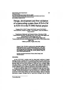
Granular filters may fail by two mechanisms (Figure 1): shear failure, which refers to failure due to entrainment of stones from the top of the filter layer by the local flow field winnowing, which is related to erosion of the finer underlying base material through the pores of the coarser filter material
1
Royal Boskalis Westminster, Rosmolenweg 20, 3356 LK Papendrecht, The Netherlands, e-mail:
[email protected] 2 Faculty of Civil Engineering and Geosciences, Delft University of Technology, Stevinweg 1, 2628 CN Delft, The Netherlands, e-mail:
[email protected] 3 Faculty of Civil Engineering and Geosciences, Delft University of Technology, Stevinweg 1, 2628 CN Delft, The Netherlands, e-mail:
[email protected]
1
2
COASTAL ENGINEERING 2014
Shear failure
Winnowing
Edge failure
Figure 1. Failure mechanisms
The first failure mechanism has been thoroughly investigated in the past and is subject of various design guidelines. Stability equations concerning shear failure are based for example on the Shields or Izbash equations. Filter criteria such as those developed by Terzaghi and Peck (1948) address the second failure mechanism. However, an optimal design is based on simultaneous erosion of the base and filter material. In other words the fail mechanisms shear failure and winnowing occur simultaneous when the structure is subjected to a critical hydraulic loading condition. Based on the principle of simultaneous erosion and the damping of shear stress in the filter a new design formula has been derived. The derivation resulted in the following equation (Hoffmans 2012):
Df d f 15
d f 50 f c , f 1 V f d ln d b50 b c ,b 1 Vb
(1)
Where: Df Thickness of the filter layer df15 Particle diameter in the filter material for which 15% of the particles is finer than df15 df50 Median particle diameter of the filter material (sieve diameter) db50 Median particle diameter of the base material (sieve diameter) αd Coefficient (Hoffmans (2012) proposed a value of αd = 1.5) Δf Under water relative material density of the filter material Δb Under water relative material density of the base material Ψc,f Critical stability parameter (Shields parameter) for the filter material Ψc,b Critical stability parameter (Shields parameter) for the base material γ Transport parameter (γ = 0.625) Vf Variation coefficient representing the non-uniformity of the filter material (Vf = 1 - df15/df50) Vb Variation coefficient representing the non-uniformity of the base material (Vb = 1 – db15/db50) The presented formula does not (directly) show the hydraulic loading conditions. This is caused by the implicit assumption of simultaneous erosion (initial motion under the same loading condition) of filter and base material and that the filter material is chosen such that it will be (just) stable during normative loading conditions. For the determination of the required filter material under flow attack one of the many design rules presented in various design guidelines can be used. The load should be damped in the granular filter layer such that the base material underneath the filter layer will be stable. This damping occurs logarithmically within the filter layer and is related to the relative layer thickness (schematised in Figure 2). The required damping of the load depends on the ratio between filter and base material. Details about the theoretical derivation of the formula are presented earlier by Verheij et al. (2012) and Hoffmans (2012). The derivation has also been included in CUR (2010).
COASTAL ENGINEERING 2014
3
Figure 2. Damping of turbulent energy within a granular layer
MODEL TESTS Test Set-up
To validate the design formula a series of tests has been executed in a flume at the Environmental Fluid Mechanic Laboratory at Delft University of Technology (Van de Sande 2012). For the experiments in the laboratory a flume with dimensions of 12m x 0.4m and a maximum water depth of 0.4m has been used, see Figure 2. During the experiments only flow conditions were considered (no wave conditions). In the flume two test sections were constructed. One section is used to determine the stability of the filter material and the other section to determine the stability of the base material. During a test the flow velocity was increased step by step. After each step the transport of filter and base material was measured. Transport of filter material has been counted visually. Therefore, colored (painted) stones were used. The transported base material was gathered in a sand trap and measured after each test. During the tests discharge, water levels and flow velocities have been measured using respectively an acoustic discharge meter, a point gage and a Vectrino ADV (Acoustic Doppler Velocimeter).
Figure 3. Flume with test set-up at the Environmental Fluid Mechanic Laboratory
Test Program
To validate the design formula a series of seven different configurations were tested in the flume (Van de Sande 2012). Variations were made in the following relevant parameters: ratio between the filter material and the base material (df50/db50), by varying both the base (db50 = 309/633 μm) and the filter material (df50 = 8.57/17.86/25.01 mm) (relative) layer thickness (Df = 8/20/27/40/57/61.5 mm) An overview of the test configurations is given in Table 1.
4
COASTAL ENGINEERING 2014 Table 1. Test configurations Test db50 df50 df50/db50 Df/df15 Df [µm] [mm] [-] [-] [mm] T01 309 8.57 27.73 2.70 20 T02a 309 25.01 80.94 1.20 27 T02b 309 25.01 80.94 1.20 27 T03 309 25.01 80.94 2.74 61.5 T04 633 25.01 39.51 1.20 27 T05 309 17.86 57.80 0.50 8 T06a 309 17.86 57.80 2.51 40 T06b* 309 17.86 57.80 2.51 40 T06c* 309 17.86 57.80 2.51 40 T07 309 17.86 57.80 3.58 57 * Tests with increased turbulence. These tests are not included in the analyses and were only used to get insight into the influence of turbulence
Test Results
The result of each test is classified based on the following three categories (see Figure 4):
Base material moves at a lower critical velocity than the filter material (uc,b < uc,f) Base and filter material starts to move at about the same critical velocity (uc,b ≈ uc,f) Filter material moves at a lower critical velocity than the base material (uc,b > uc,f)
Categorizing the results enables us to validate the design formula. The different test configurations (Table 1) were chosen such that simultaneous erosion or nearly simultaneous erosion was expected.
Filter material moves first
D f d f 15
Simultaneous movement Base material moves first
d f 50 d b 50 Figure 4. Categorization of movement of filter and base material
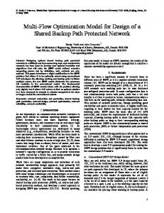
As mentioned earlier transport of base and filter material is measured during each test, for each loading condition. The flow velocity is increased step by step until significant transport of base or/and filter material is measured. Figure 5 and Figure 6 present the results of test T01 and T02a. In these figures the transport of base and filter material is presented against the increasing loading condition (flow velocity). During test T01 transport of filter material is measured after the flow velocity had been increased with a number of steps. In this test no (or insignificant) transport of base material is measured. This test has been categorized in the category: “Filter material moves at a lower critical velocity than the base material”. Figure 6 presents the results of test T02a, in this figure it can be seen that transport of base material is measured before any transport of filter material is measured. This test has been classified in the category: “Base material moves at a lower critical velocity than the filter material”. For each test the transport of base and filter material in relation to the flow velocity has been analysed, and based on the transport of material the test has been categorized in one of the three categories. An overview of all test results is given in Table 2.
5
COASTAL ENGINEERING 2014
Figure 5. Test results test T01, transport of base material (left figure) and filter material (right figure)
Figure 6. Test results test T02a, transport of base material (left figure) and filter material (right figure) Table 2. Test results Test uc,b < uc,f T01 T02a X T02b X T03 T04 T05 X T06a T07
uc,b ≈ uc,f
uc,b > uc,f X
X X X X
Analyses
After the execution of the model tests an extensive analysis was made based on the model tests and model tests performed in the past. The data-set has been extended with model tests performed during earlier research of: Bakker (1960), Haverhoek (1968), Wouters (1982), Konter et al. (1990), Van Huijstee and Verheij (1991) and Van Velzen (2012). Not all these studies were directly related to geometrically open filter structures, however the performed tests (test data) gave information about the stability of base and filter material and each of these tests could be classified in the categories mentioned in Figure 4. An overview of all the tests is presented in Figure 7 (for a more extensive overview see Van de Sande (2012)). Different configurations of the formula of Hoffmans (2012) have been analysed. Adjustments were made to the formula and the influence on the spreading of the test results has been compared. One of the analysed adjustments was a change in the representation of the relative layer thickness. Instead of relating the relative layer thickness to the df15 of the filter material, the relative layer thickness is related
6
COASTAL ENGINEERING 2014
to the df50. Figure 8 presents the model test results were the relative layer thickness is related to df50 instead of the df15. In Figure 7 and Figure 8 the test results are categorized in one of the three categories presented in Figure 4. The spreading of the test results is indicated by an upper and lower limit, based on these limitations the graph is divided in the three categories. For comparison the original proposed alpha values of Hoffmans (2012) and the formula of Wörman (CUR 2012) are plotted. The grey area on the left of the figures presents an area of geometrically closed filter structures. The shaded area is a transition area between geometrically closed and geometrically open filter structures. Whether situations in this shaded area can be classified as a geometrically closed filter depends on the geometrically closed filter rules used (e.g. Cistin and Ziems (Heibaum, 2004)) and the properties of the filter and base material (i.e. the uniformity of the gradings: d60/d10). When comparing Figure 7 with Figure 8 the reduction in spreading is clearly visible. Based on this comparison one can conclude that the relative layer thickness is better represented when related to the df50 instead of the df15. In Figure 7 there are some extremes (test results) visible, these extremes are more in line with the other tests in Figure 8.
Df/df15 [-]
8 6 4 2
ör
s) limit ffman upper by Ho d e s propo =1.5 (
d
er 90% low
7 6
1 4
0
m an
filter material eroded before base material simultanious erosion base material eroded before filter material
W
10
Geometrically closed filters
12
5
lower limit
3 2
1
2
10
3
10
10
df50/db50 [-] Figure 7. Classifications of the model test results (numbered tests are tests of Van de Sande 2012)
Df/df50 [-]
8 6 4 2 0
ör m an
filter material eroded before base material simultanious erosion base material eroded before filter material
W
10
Geometrically closed filters
12
(propo d =1.2
s ed by
ns ) Hoffma
it upper lim er w lo % 90 1 4
7 6
3
5
2
1
lower limit 2
10
10
3
10
df50/db50 [-] Figure 8. Classifications of the model test results, were the relative layer thickness is related to the median particle diameter (df50) of the filter material (numbered tests are tests of Van de Sande 2012)
The different configurations of the design formula are analysed in more detail. For each test within the range of simultaneous erosion the representative d value has been determined. The distribution of these d values is presented in Figure 9, where the density function of the d values of the relevant model tests corresponding to the formula with a relative layer thickness Df/df15 (left figure) and corresponding the formula with a relative layer thickness Df/df50 (right figure) are plotted. In the left figure two groups of d values can be distinguished, tests with d values between 0.3 and 1.0 and tests with d values around 1.5. Taking a closer look to the latter group of tests) showed that all these tests are tests with wide graded filter material. When relating the relative layer thickness to the median sieve
0.5
0.5
7
COASTAL ENGINEERING 2014 0.4
0.4
f(x)
f(x)
diameter (df50) of the filter material (right figure) the wide 0.3 0.3 graded tests are well correlated with the other tests. 0.2
0.2
The original formula as proposed by Hoffmans (2012) gives unrealistic values for situations with wide relative layer thickness is better represented 0.1graded filter material. Model tests showed that the 0.1 when related to the median sieve diameter of the filter material. 0
0
0.5
1
1.5
0
2
0
0.5
1
1.5
2
For (very) wide graded [-] filter materials the original formula would result in[-]filter layers with a d d (unrealistic) thin required thickness. 0.5 0.5
Df d f 15
0.4 0.4
d f 50 f c , f 1 VGf d ln d 1 V Gb b 50 b c ,b
0.5
0.4
d f 50 f c , f 1 VGf d ln d 1 V Gb b 50 b c ,b
f(x)
0.3
f(x)
0.3 0.3 0.2 0.2
0.2
Wide graded
0.1 0.1
1.5
Df d f 50
00 00
2
0.5 0.5
11 [-] [-] dd
1.5 1.5
0.1 0
22
0
0.5
1 [-] d
1.5
2
Figure 9. Distribution of values based on relevant model tests Table 0.5 3. Alpha values Deterministic approach Lower boundary 90% lower Upper boundary
0.4
d ,d f(x)
f 15
0.3 d ,d f 50
Probabilistic approach E(αd) Var(αd)
0.27
0.98
1.75
0.75
0.16
0.24
0.69
0.82
0.46
0.03
0.2
CONCLUSIONS
1.5
2
0.1 The analysis showed that equation (1) is valid for single layered geometrically open filter structures loaded by currents, but two adjustments to the original design formula are proposed (Van de Sande002012): 0.5 1 1.5 2 The relative layer thickness fits better when related to the median sieve diameter (df50) of the filter [-] d material The d value based on df15 as proposed by Hoffmans (2012) is too conservative
Based on this research the following representation of the design formula for single layered geometrically open filter structures is proposed (Van de Sande 2012):
Df d f 50
d f 50 f c , f 1 V f d ln d b50 b c ,b 1 Vb
(2)
With the following values for alpha: Deterministic approach: αd = 0.82, safe upper-limit αd = 0.69, 90% confidence limit
Probabilistic approach: Log-normal distribution, with: E(αd) = 0.46 Var(αd) = 0.03
The formula can be used as a design tool for single layered geometrically open filter structures. This can been done in two steps: first, determine the required filter material to withstand the currents (e.g. using Shields (1936)); secondly, using the properties of the filter and base material, the required layer thickness can be determined using the presented formula. It should be taken into account that
8
COASTAL ENGINEERING 2014
when using the formula the properties of the chosen filter material should be used and not the dimensions calculated in the first step. Using a stable geometrically open filter structure instead of the classical multiple layered geometrically closed filter structure results in an easier to construct protection against erosion. It also can result in smaller amounts of required material. SIMPLIFIED FORMULA FOR FIRST ESTIMATE
When only limited information is available, a simplified version of equation (2) can be used. In this simplified version (equation (3)) are the relative densities and shape factors represented by a parameter . It is recommended to use the simplified formula only as a first estimate and only if the base and filter material are normal graded materials.
Df d f 50
d f 50 c , f d ln d b50 c ,b
(3)
The parameter in the formula represents the relative densities and the shape factor of the materials. Representative values have been determined based on the set of model tests. It should be noted that no safety factor is included within this equation. It is recommended to use a safety factor, or a value with a low probability of exceedence, to take the uncertainties of the unknown parameters (which are represented by ) into account. The following values for are proposed: Deterministic approach: β = 1.39, 90% confidence limit β = 1.60, 99% confidence limit
Probabilistic approach: Log-normal distribution, with: E(β) = 1.13 Var(β) = 0.20
RECOMMENDATIONS
To increase the range of validated applicability of the design formula additional tests are proposed, focusing on the following situations: Turbulent/highly energetic situations (e.g. behind a backward facing step); Protections on a slope; Multiple layered open filter structures. Next to increasing the range of applicability of the formula, research into damping of turbulence within granular layers is proposed. This will allow for further optimization of the design formula, making it applicable for any loading conditions. It will also give better insight into the effective damping length within a granular filter layer. Detert et all (2010) showed that the load is decreased exponentially in the porous layer with a decay distance (effective damping length) of 1 to 2 times the equivalent roughness (Nikuradse grain roughness). Other (older) researches showed a wide range of effective damping length, Van Os (1998) gives a layer thickness of 1.5 df50, while Klar (2005) gives a layer thickness of 4 to 5 df50. REFERENCES
Bakker, M.J. 1960. Onderzoek steenstortingen, Deel III, Uitspoeling van zand door een laag grind (in Dutch), report M633, Waterbouwkundig Laboratorium, Delft CUR. 2010. CUR 233: Interface stability of granular filter structures, Gouda Detert,M., V. Weitbrecht, G.H. Jirka. 2010. Laboratory measurements on turbulent pressure fluctuations in and above gravel beds, Journal of hydraulic engineering, ASC/October 2010, 779789 pp. Haverhoek, F.J. 1968. Uitspoelen van zand door een laag van fosforslakken (in Dutch), report M1012, Waterbouwkundig Laboratorium, Delft Heibaum, M.H. 2004. Geotechnical filters - The important link in scour protection, Proc. of 2nd ICSE, Singapore Hoffmans, G.J.C.M. 2012. The Influence of Turbulence on Scour and Erosion, Deltares Select Series, Delft
COASTAL ENGINEERING 2014
9
Klar, M. 2005. Design of an endoscopic 3-D Particle-Tracking Velocimetry system and its application in flow measurements within a gravel layer, PhD Thesis, University of Heidelberg Konter, J.L.M., H.J. Verheij , R.J. de Jong, J.H. Bouwmeester, J. van Zwol. 1990. Haalbaarheid van de toepassing van niet-zanddichte bodemverdedigingen (in Dutch), report Q891, Waterloopkundig laboratorium Shields, A. 1936. Anwendung der Aehnlichkeitsmechanik und der Turbulenzforschung auf die Geschiebebewegung, Mitteilungen der Preußischen Versuchsanstalt für Wasserbau und Schiffbau, Berlin Terzaghi, K., R.B. Peck. 1948. Soil Mechanics in Engineering Practice, John Wiley and Sons, New York Van Huijstee, J.J.A. and H.J. Verheij. 1991. Verruiming ontwerpregels voor filters in bodemverdedigingen (in Dutch), report Q572, Waterbouwkundig Laboratorium Van de Sande, S.A.H. 2012. Stability of open filter structures, revision Augustus 2013, MSc. Thesis, Delft University of Technology Van Os, P.P.A.M. 1998. Hydraulische belasting op een geometrisch open filterconstructie (in Dutch), MSc.Thesis, Delft University of Technology Van Velzen, G. 2012. Flexible scour protection around circular piles, MSc. Thesis, Delft University of Technology Verheij, H.J., G. Hoffmans, K. Dorst, S.A.H. Van de Sande. 2012. Interface stability of granular filter structures under currents, 6th International Conference on Scour and Erosion, Paris Wörman, A. 1989. Riprap protection without filters, Journal of Hydraulic Engineering, 115 no.12 Wouters, J. 1982. Gedrag fosforslakken als bodembeschermingsmateriaal onder stroomaanval en verval (in Dutch), report R460, Waterloopkundig laboratorium