Pontus Bostr¨om | Matti Linjama | Lionel Morel | Lauri Siivonen | Marina Wald´en
Design and Validation of Digital Controllers for Hydraulics Systems
TUCS Technical Report No 800, December 2006
Design and Validation of Digital Controllers for Hydraulics Systems Pontus Bostr¨om
˚ Abo Akademi University, Department of Information Technologies Turku Centre for Computer Science Joukahaisenkatu 3-5, 20520 Turku, Finland
[email protected]
Matti Linjama Tampere University of Technology, Institute of Hydraulics and Automation P.O. Box 589, FI-33101 Tampere, Finland
[email protected]
Lionel Morel
INRIA - Campus universitaire de Beaulieu 35042 Rennes Cedex, France
[email protected]
Lauri Siivonen
Tampere University of Technology, Institute of Hydraulics and Automation P.O. Box 589, FI-33101 Tampere, Finland
[email protected]
Marina Wald´en
˚ Abo Akademi University, Department of Information Technologies Turku Centre for Computer Science Joukahaisenkatu 3-5, 20520 Turku, Finland
[email protected]
TUCS Technical Report No 800, December 2006
Abstract In order to increase the flexibility and performance of hydraulically actuated machines there is a demand for more intelligent controllers. This leads to a rapid increase in complexity of the control systems. To manage the complexity and to ensure reliability of these systems, adequate software development methods are needed. In this work, we propose a methodology for structured design of digital hydraulics controllers in Simulink/Stateflow. A model architecture based on mode-automata is introduced to separate control and data processing. Furthermore, design by contract is advocated as a method for system development. The contracts can be used to mathematically reason about correctness of Simulink/Stateflow models and thereby increase the safety and reliability of the developed systems. The usefulness of these concepts are demonstrated on a larger case study from the area of digital hydraulics.
Keywords: Controller Architecture, Mode-Automata, Simulink/Stateflow, Design by Contract, Reliability
TUCS Laboratory Distributed Systems Design Laboratory
1
Introduction
There is a trend toward adding more intelligent controllers in hydraulically actuated machines in order to increase their flexibility and performance. The trend is also to replace hydromechanical functions - such as load-sensing - with sensors, electrically controlled valves and intelligent control. An extreme example is the Digital Hydraulics technology [1] , in which simple on/off valves are used together with intelligent control. The result of these trends is that complexity of control systems increases rapidly. Modern systems also have high requirements on performance, safety and reliability. To handle these requirements, appropriate software development and validation methods are needed. This paper presents development techniques used for a digital hydraulics controller with energy saving [2]. Since high reliability of the controller software is desired, formal software design methods are beneficial. These methods enable mathematical reasoning about correctness of models. They also enable mathematical proofs that certain properties are satisfied in the system. Among these properties, the focus will mainly be on safety properties, which establish that some bad behaviour will never happen. The work is carried out using Simulink1 /Stateflow2 , which have become a widely used tool for model based design of control systems. Our propositions articulate around two main points. First, we advocate a particular software architecture for developing mode-based systems in Simulink. Second, formal techniques for increasing the confidence that the system works correctly are presented. Related techniques have previously been successfully applied to safety-critical systems e.g. [3]. What we propose here is to adapt those techniques to the development of systems where safety issues are less critical and developers are not formal methods experts. The aim is here to maximise the efficiency and ease of use of these methods. The rest of the paper is structured as follows. In Section 2 the digital hydraulics application is presented. Section 3 describes the development of controllers in Simulink/Stateflow, while Section 4 gives an example and outlines the controller architecture. Design by contract of models is introduced in Section 5 and analytical verification of mode switching based on this method is presented in 6. Section 7 gives the conclusions of the paper.
2
The Digital Hydraulics System
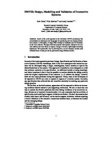
The idea of digital hydraulics is to use simple on/off valves [1] together with an intelligent controller to achieve desired performance. Figure 1 shows an overview of such a system. The hydraulic cylinder is controlled by four digital flow control units (DFCU) with five on/off valves each (P Ai , P Bi , ATi , BTi , i = 1..5). The configuration of a DFCU gives the open and closed valves and thereby controls the flow of fluid through it. The configuration of the first DFCU (uAT ) controls the flow from A to tank, the second controls the flow of fluid from the pump to A (uP A ) , the third (uP B ) from pump to B and the last (uBT ) controls the flow from B to tank. To control the speed of the piston, suitable combinations of valves are opened. The controller computes optimal valve configurations at each sampling time, taking into account pressure limitations. The controller has different running modes for normal motion and energy saving motion. Energy efficient modes 1 Simulink, 2 Stateflow,
Mathworks Inc, http://www.mathworks.com Mathworks Inc, http://www.mathworks.com
1
A AT1
B PA1
PB1
BT1
T
T
ATn DFCU A®T
PAn DFCU P®A
PBn DFCU P®B
BTn DFCU B®T
P
Figure 1: Overview of a hydraulic cylinder controlled by a set of digital control flow units should then be used whenever possible. Due to the complex calculations needed, the software for the controller is large and involves both signal processing and discrete control logic to handle the switching of modes.
3
Controller Development in Simulink/Stateflow
A controller usually consists of two parts; signal processing and control logic. Simulink is used to describe the signal processing and Stateflow is used to describe the control logic. In this paper the control logic consists of switching between control modes. Stateflow is a state-machine implementation for Simulink similar to Statecharts [4]. It is a sequential and deterministic language for creating the supervisory control logic in control applications. Consider the Stateflow chart in Figure 2. The square boxes are states and the circles are junctions. An arrow is referred to as a transition segment. Stateflow supports hierarchical statemachines containing both or-state and and-states. In an or-state (s2 ) only one sub-state is active modelling sequencing of transitions, while in a and-state all sub-states are active modelling parallelism. Transition segments in Stateflow can be labelled by events (e), guards (g1 , g2 , h1 , h2 ), and actions (act). The action language of Stateflow is very expressive and contain many advanced features for defining behaviour. However, some of these features have counter intuitive semantics and are difficult to use correctly. Therefore, to aid verification and to only use constructs with a simple semantics, only a subset of Simulink/Stateflow should be used. Guidelines for development of controllers 2
[g_2] [g_1]
s_2
r_1
s_1 e [h_1]/act
[h_2]
r_2
Figure 2: A schematic example of a Stateflow chart using Simulink/Stateflow have been developed to increase the readability and maintainability of models [5]. In order to have efficient code generation suitable for safety critical systems, even stricter guidelines need to be followed [6, 7]. Even when the guidelines above are followed formal verification is difficult in Stateflow, due to the large number of features for defining behaviour. When considering ease of verification, Simulink often offers a better choice for defining behaviour. Additionally, Simulink/Stateflow models can analysed by graph based techniques if textual descriptions are avoided, whenever it is possible. The following restrictions to Stateflow are used in this paper: • Activities inside states are not allowed in Stateflow. Simulink is instead used to define all behaviour inside states (modes). • Transitions that cross composite state boundaries are not allowed. • Events, actions and condition actions are not allowed on transition segments. • Transition segments are restricted to only be labelled by a guard (condition) name, e.g., g1 , g2 in Figure 2. A guard name is always an input port name in the Stateflow block. In practise we often also need the negation ¬g if guard g is used. Therefore guards of the type [g] or [∼ g] are allowed on the transition segments. Conjunction (and) and disjunction (or) of conditions can be implemented using junctions. These constraints restrict Stateflow to a safe subset that is easy to analyse, and yet sufficiently powerful to be used in practise.
3.1
Semantics of the considered subset of Stateflow
To get an understanding of how a Stateflow chart is executed a short introduction to the Stateflow semantics is needed. Due to the restrictions in this paper, transition segments can be labelled by a guard condition of the form [g] or [∼ g]. A transition is a sequence of transition segments connected by junctions that starts and ends in a state. The guard of a transition is given as the conjunction of the guard conditions on the individual transitions segments, e.g., g1 ∧ g2 for the transition between s1 and s2 in Figure 2. A transition is enabled, if its guard evaluates to true. Transitions with the source state higher in the state hierarchy have higher priority, while the ones with the same source either have a fixed priority given by the developer or a priority given by the internal rules of Stateflow. The internal rules in Stateflow for assigning priorities depends on 3
the graphical layout of the diagram and is therefore not safe to use. The explicit ordering mechanism should therefore always be used. During the execution of the Stateflow chart, a subset of the states are active. The transitions between states describe how the set of active states changes. When the chart is executed, the enabled transitions from the currently active states are computed. The enabled transition with the highest priority is then executed and the active states are changed to the destination of the transition. If an and-state is active several transitions can be executed concurrently. If the destination of a transition is a composite state, then the corresponding default transitions are also executed.
4
Controller Architecture Example
A good architecture is needed in order to structure the system. This guarantees that the controller is maintainable, extensible and the logic of the controller is easy to understand. The architecture proposed here separates control logic from signal processing. The mode specific behaviour is, hence, isolated from the parts common for all modes.
4.1
Controller overview
The controller presented here is used for energy saving digital hydraulics in [2]. The focus in this paper is on architecture and verification of the system, while [2] presents the functionality of the system. An overview of the different parts of the controller is given in Figure 3. Most of the controller functionality is common for all modes. The mode specific behaviour is given in subsystem Selection of control mode. The inputs to the controller are position, x, reference position, xref , and reference speed, vref , of the piston, as well as pressure provided by the pump pP and the cylinder chamber pressures, pA and pB . Based on this information, the controller then computes the optimal valve configurations uP A , uAT , uP B and uBT . The subsystem selection of control mode computes optimal pressure references for the pump (pP ref ) and for the chamber pressures (pAref and pBref ) based on the reference speed vrC , (filtered) chamber pressures (ˆ pA and pˆB ) and pump pressure (pP ref ). Furthermore, it provides mode specific parameters in the signal MODE . The signals from the mode selection block are then used for the model-based controller to determine the optimal valve configuration independent of the running mode.
4.2
Mode switching
To increase readability and ease verification of the mode switching system an appropriate design has to be used. Mode-automata [8, 9, 10, 11, 12] is such an architecture for developing mode-based systems. It is used for systems that consist of a set of running modes, where each mode is associated with modespecific signal processing. The switching between modes is described using a state-machine (here a Stateflow chart), where each transition is guarded by a condition. Each non-composite state in the Stateflow chart is connected to an enabled subsystem in Simulink giving the mode specific behaviour. Figure 4 shows a simplified version of the core of the mode switching logic. The subsystem Conditions computes the conditions that are used to decide 4
2 x_ref
x_ref
CONTROLLER PARAMETER CONSOLE
5
Figure 3: Overview of the controller
4 x 3 v_ref
x
v_rC
v_ref
[P_T]
v_ref
1 u_PA
u_AT
2 u_AT
u_PB
3 u_PB
u_BT
4 u_BT
From (p_T) pP
Motion controller
5 pP
1 pA & pB
u_PA pT
p_P
pA_ref
pAr
v_rC
pB_ref
pBr
pA_hat
pA_hat
MODE
MODE
pB_hat
pB_hat
pP_ref
pA & pB
Filtering of pressures
5 pP_ref
pA_hat
Selection of Control Mode pB_hat
Model−based controller
6
Figure 4: Simplified view of the Selection of control mode subsystem
pP_ref_in vref_positive vref_NOT_positive vref_negative F
pP_ref
pP_ref
vref_NOT_negative M1_feas M1_NOT_feas
Pump pressure references
M1_poss M1_NOT_poss
1 v_rC
v_ref
M2_feas M2_NOT_feas M2_poss M2_NOT_poss
3 pA_hat
pA
4 pB_hat
pB
M3a_feas F
F
M3a_NOT_feas M3a_poss M3a_NOT_poss M3b_feas
From p to F
M3b_NOT_feas M3b_poss
2 p_P
p_P
M3b_NOT_poss
vref_positive vref_negative
Target_Mode_0
Target_Mode_1
Target_Mode_1
vref_NOT_negative
pP_ref_out
M1_feas M1_NOT_feas
Target_Mode_2
M1_NOT_poss
Target_Mode_3a Target_Mode_3a
M2_feas M2_NOT_feas
4 pP_ref
Target_Mode_2
M1_poss
Target_Mode_3b Target_Mode_3b
M2_poss
Select pump pressure reference
M2_NOT_poss M3a_feas
Actual_Mode_0
Actual_Mode_0
Actual_Mode_1
Actual_Mode_1
Actual_mode_2
Actual_Mode_2
Actual_Mode_3a
Actual_Mode_3a
Actual_mode_3b
Actual_Mode_3b
M3a_NOT_feas M3a_poss M3a_NOT_poss M3b_feas
MODE
M3b_NOT_feas
3 MODE
M3b_poss M3b_NOT_poss
M3a_efficient
M3a_efficient
M3b_efficient
M3b_efficient
Conditions
Target_Mode_0
vref_NOT_positive
Mode switching logic (Stateflow chart)
Mode vector Actual_Mode_0 Actual_Mode_1 Actual_Mode_2
Mode switching parameter console
pA_ref
1 PA_ref
pB_ref
2 pB_ref
Actual_Mode_3a Actual_Mode_3 pP F pA_hat pB_hat
A− and B−side pressure references
[M1_feas]
Actual_Mode
Actual_Mode_1
2 Actual_mode_2
[M3a_feas]
[M2_feas] [vref_positive] [vref_negative]
[M3b_feas]
[M1_feas]
[vref_NOT_positive] [vref_NOT_negative] [M2_feas]
[~M1_feas] [~M2_feas]
[Target_Mode_3a]
Actual_Mode_0 [~M1_feas]
[Target_Mode_3b]
[~M3a_feas]
[~M2_feas] [~M3b_feas] [~M3a_feas] Actual_mode_3b
[~M3b_feas]
[vref_NOT_negative]
[Target_Mode_3b]
Actual_Mode_3a
[vref_NOT_positive] [vref_negative] [vref_positive]
[M3a_feas]
[M3b_feas]
[Target_Mode_3a]
Figure 5: Switching of the actual mode when modes should be switched, vref positive, . . . , m3b efficient . These conditions correspond ultimately to the guards [g] that are used in the Stateflow chart. Each output from the subsystem is a boolean stating wether the condition holds or not. The Stateflow chart outputs which modes are currently active. The active modes then triggers enabled subsystems giving the mode dependent behaviour. There are two parallel modes (i.e. sub-states of an and-state) Target mode and Actual mode. The enabled subsystems activated by target mode are first used for computing the pressure reference (pP ref ) for the freely adjustable pump pressure. The best actual mode is then determined based on the actual pump pressure pP . The subsystems enabled by the actual mode then compute chamber pressure references (pAref and pBref ), as well as mode specific parameters (MODE ). The Stateflow chart determines the running mode of the system. Figure 5 shows the switching of the actual mode. The switching of the target mode is similar. The actual mode consists of the following submodes [2]: 0 Stopped motion. If the reference speed is close to zero (vref NOT positive(vrC ) ∧ vref NOT negative(vrC )) or no other mode is feasible (¬Mi feas(F, pP , ∆pmin )) this mode is used. 1 Normal extending motion. This mode is selected if the reference speed is greater than a threshold value (vref positive(vrC )), the mode is feasible (M1 feas(F, pP , ∆pmin )) and energy saving should not be used (¬(M3a feas(F, pP , ∆pmin ) ∧ Target mode 3a)). The last condition is derived from the priority of the transitions. 2 Retracting motion. This mode is similar to mode 1, but it involves movement in the opposite direction. 3a Extending energy saving motion. If the reference speed is greater than a threshold value (vref positive(vrC )) and energy saving can be used (M3a feas(F, pP , ∆pmin ) ∧ Target mode 3a), this mode is selected. 3b Retracting energy saving motion. This mode is similar to mode 3a, but it involves movement in the opposite direction . 7
7 F
1 Actual_Mode_0 8 pA_hat 9 pB_hat
pA_hat
pA_ref
pB_hat
pB_ref
Merge
pA_ref and pB_ref, Mode 0
1 pA_ref
2 Actual_Mode_1 F
6 pP
pP
[PMAX]
P_MAX
[PMIN]
P_MIN
[DP_NOM]
pA_ref
pB_ref
DP
pA_ref and pB_ref, Mode 1 3 Actual_Mode_2 F pP
[PMAX]
P_MAX
[PMIN]
P_MIN
[DP_NOM]
pA_ref
pB_ref
DP
pA_ref and pB_ref, Mode 2 4 Actual_Mode_3a F pP
[PMAX]
P_MAX
[PMIN]
P_MIN
[DP_NOM]
pA_ref
pB_ref
DP
pA_ref and pB_ref, Mode 3a 5 Actual_Mode_3 F pP
[PMAX]
P_MAX
[PMIN]
P_MIN
[DP_NOM]
pA_ref
pB_ref
Merge
DP
pA_ref and pB_ref, Mode 3b
2 pB_ref
Figure 6: Definition of chamber pressure references pAref and pBref in each mode inside subsystem A- and B-side
Due to noise in the input signals there is a problem with excessive mode switching when the signals remain close to a switching condition. To remedy this problem, e.g. the condition vref NOT positive(vrC ) is not the negation of vref positive(vrC ), but it contains extra conditions to inhibit switching between modes, when signal values remain close to this switching condition. The conditions vref NOT positive(vrC ) and vref positive(vrC ) can, hence, evaluate to false at the same time. A further measure to prevent excessive switching is that some conditions also have to evaluate to true for a certain amount of time in the Simulink diagram before they become true in the Stateflow chart. The actual modes are used to compute the optimal chamber pressures references pAref and pBref , which is illustrated in Figure 6. The final pressures are computed with merge-blocks that take the latest value computed by an enabled subsystem. 8
4.3
Mode Dependent Behaviour
The mode-automata architecture puts restrictions on the way the system designer can describe behaviour. The first restriction concerns the memory inside enabled subsystems and the second the connection of enabled subsystems to merge blocks. Consider the case when a memory block inside a mode enabled system stores a signal value. When the mode is exited and then re-entered the signal value stored in the block refers to possibly a very old value. This can lead to problems in the control algorithms. For example, if the mode dependent behaviour is a PI-controller the integrator might have a value not relevant anymore. The mode dependent behaviour should, therefore, either not contain blocks with memory or the memory should be reset whenever the mode is entered in order to ensure predictable behaviour. The mode selection system should also define the value of all output signals all the time. Furthermore, each signal value should be uniquely defined. Hence, every enabled subsystem should be connected to merge blocks to obtain the final result and every merge block should have exactly one enabled input at all times.
5
Design by Contract
The term Design by Contract was first used by B. Meyer in the Eiffel programming language [13]. The idea of Design by Contract is that software should have precise checkable interface specifications. Each component should state explicitly what conditions on the inputs it require from the environment and what conditions on the output it ensures. Optionally, the component can also state what internal conditions it will always maintain. The theory behind contracts is discussed in [14]. Design by Contract ideas are implemented in e.g. Eiffel [13], JML [15] for Java and in Spec# [16] for C#. These languages are accompanied by various tools for compiling, static checking and dynamic checking (testing). Design by contract can be used for assume-guarantee reasoning. The idea behind assume guarantee style reasoning about system correctness is that each component only guarantee that it functions correctly as long as its assumptions about the environment are satisfied. This enables compositional reasoning, since components can be verified individually. Assume-guarantee reasoning about embedded and hybrid systems have been investigated by several authors [17, 18, 19, 20].
5.1
Design by Contract in Simulink
A Simulink subsystem can be viewed as a tuple (i, o, p, f ), where i is a set of input signals, o is a set of output signals, p is a set of parameters and f is a function that update the output signals based on the parameters and input signals o = f (p, i, x), where x is the memory contained in block inside the subsystem. To use Design by Contract and enable assume-guarantee reasoning about correctness in Simulink we need to be able to state what a subsystem assumes of its environment and what it guarantees. To express these kinds of constraints we need two types of conditions: assume conditions and guarantee conditions. Assume condition violations and guarantee condition violations are interpreted in different ways. Assume violations are not the responsibility of the subsystem the condition belongs to, while a guarantee violations is the 9
responsibility of that subsystem. Four types of conditions can be identified for stating properties about different aspects of a subsystem. • Initialisation condition R(p). This is an assume-condition for stating properties describing the parameter values the subsystem expects. • Pre-condition P (p, i). This conditions is an assume-condition for stating pre-conditions on the input values from the environment. • Invariants I. These conditions are guarantee-conditions for stating internal conditions (invariants) that the subsystem should maintain. • Post-condition Q(p, i, o). This is again a guarantee-conditions giving the conditions on the output that the subsystem guarantees. The parameter values cannot depend on the signals in the subsystem and, therefore, the condition describing the parameters depends only on the parameter values. The environment cannot see anything inside the subsystem block. Hence, the pre-condition can only state properties about the input signals. The invariant condition can state properties about inputs, outputs and all internal signals. Since a post-condition again guarantees a condition for the environment, it can only state properties about the input and output signals of the block. Note that it is here assumed that all signals used in the conditions have the same timing. Contracts over signals with different timing is more complicated and require special treatment. To illustrate how contracts can be used to define the interfaces of components, a contract is defined for the subsystem enabled by actual mode 1 in Figure 6. The subsystem uses constants AB and AB giving the areas of the A and B sides of the piston. The input signals are pmin , pmax , F , pP , and ∆p. The block computes the values of pAref and pBref . The following conditions can be given. RM1 (AA , AB )=(A ˆ B < AA ) PM1 (pmin , pmax , F, pP , ∆p)= ˆ (pmin < pmax ∧ pmin > 0 ∧ ∆p > 0 ∧ M1 feas(F, pP , ∆pmin ) QM1 (pmin , pmax , pP , pAref , pBref )= ˆ (pmin ≤ pAref ≤ pmax ∧ pmin ≤ pBref ≤ pmax ∧ pP − pAref ≥ ∆pmin ∧ pBref ≥ ∆pmin )
(1)
The initialisation condition states that the piston area on the A side is greater than the piston area on the B side, while the pre-condition states that actual mode 1 is feasible. Furthermore, the post-condition states that pAref and pBref are within limits pmin and pmax . Finally, in order to ensure controllability of the system the pressure over the valves should not be smaller than ∆pmin . There are several benefits in using Design by Contract in Simulink. Model reuse is becoming more important and the contracts are useful for this purpose, since they state the exact environment where the component is intended to work. Since each component is accompanied by a contract, assumptions components make about each other are clearly stated. This means that responsibility for error handling becomes clearer. The developer is also forced to think more about the interfaces of components and thereby inconsistencies can be identified earlier in the design process. Erroneous components can be identified by finding components that first broke a contract. The conditions used in the design by contract gives concrete condition that can be checked during testing and validation to ensure that the models work as intended. Design by contract 10
also makes compositional verification possible, since we only need to show that each component satisfies its contract and that the contracts between different connected components are compatible. Note that contracts (which are specifications) should not be confused with error handling (which handles exceptional behaviour). A contract violation always means that the system is incorrect. Error handling should be used to ensure that the contracts can be maintained regardless of possible errors that can occur.
5.2
Correctness of Models
Contracts can be used to define correctness of models. A model is correct if it is impossible for contract violations to occur. Consider a subsystem block C with assumption about parameters RC , pre-condition PC , invariant IC and post-condition QC . Assume there are n blocks B1 , . . . , Bn connected to the inputs of C with assumption about parameters RB1 , . . . , RBn , pre-conditions PB1 , . . . , PBn and post-conditions QB1 , . . . , QBn . The correctness conditions can be defined as follows: Correctness of the Parameters of C. RC holds for the parameter values.
The parameters of C are correct if
Correctness of C. The block C is correct iff when RC holds for the parameter values and PC holds for all input values so far, then IC and QC also hold. Correct connection between components. The connections between blocks B1 , . . . , Bn and C is correct if, whenever the initialisation condition holds for the parameters and the blocks Bi are assumed correct then the precondition of C holds. ^ RC ∧ (RBi ∧ PBi ∧ QBi ) ⇒ PC (2) 1≤i≤n
Signals from a subsystem to itself should be avoided, since PC ⇒ PC is trivially true. The condition PBi is also only needed, if QBi refers to the input of Bi . Note, that this notion of correctness does not ensure that the model behaves as desired, since contracts often do not capture all properties of the system. It can also sometimes be difficult to derive contracts from the system requirements. However, many types of errors can be found using contracts, such as interface errors between subsystems and safety condition violations.
5.3
Implementation of Design by Contract in Simulink
Design by Contract can be implemented using the model validation blocks in Simulink, which consists of different types of assertion blocks. These assertion blocks can be used to give the contract conditions. The different types of conditions need to be identifiable, since violations of them are interpreted in different ways. One way to distinguish a block is to prefix the name of the block with either Assume or Guarantee. Verification of assume conditions for parameters are best implemented as a preprocessing step in Matlab. Scalability suffers since, adding assert blocks to the model can make it more cluttered and harder to read. To remedy this problem, the pre- and postconditions can be added to a separate contract library. Using the Matlab model 11
constructions commands a validation model can be created from the original model and the contracts. This model contains the pre- and post-conditions inserted into the model in the appropriate places. Efficient and user friendly implementation of contracts is still ongoing research. To ensure that a model is correct, the correctness constraints have to be satisfied. It is straightforward to ensure that no parameter assumption violations exists. Since all parameters are constants, it is sufficient to check that these constant values satisfy the conditions directly after they have been defined. The most challenging problem is to show that a subsystem always satisfies its invariant and post-condition. Tools such as ss2lus3 [21, 22] and the validation tools for Lustre [23, 24] can be used. If no tool for for static verification exist the subsystem need to be validated by testing. Valid test cases consists of any input that satisfies the pre-condition. The post-condition and invariant are then used as the acceptance test. The final condition is the correctness condition for connections between subsystems, which consist of a logical formula. This means that it is easier to verify the composition of subsystems than the correctness of subsystems themselves.
6
Analytical Validation of the Mode-Switching System
Design by contract is used to describe the assumption the subsystem selection of control mode makes about its environment and what it guarantees. If the subsystem conforms to the mode-automata architecture and the mode dependent behaviour does not contain memory, it is possible to derive simple conditions for the correctness. The memory requirement might seem very restrictive, but often the memory is more naturally placed as a common part of all modes. If no memory is present in mode specific behaviour it can also potentially reduce problems with transients when switching modes.
6.1
Correctness conditions
To prove that the mode transition subsystem (i, o, p, f ) satisfies its contracts we derive conditions based on the behaviour in each mode and the transitions between modes. Assume that mode m has behaviour given by the enabled subsystem (im , om , pm , fm ). Since the enabled subsystem m does not have memory, the output is a function of the input and the parameters. The following correctness condition is then derived (see correctness of subsystems in Subsection 5.2). Rm (pm ) ∧ Pm (pm , im ) ∧ (om = fm (pm , im )) ⇒ Qm (pm , im , om )
(3)
The condition states that if the assumption about constants, the pre-condition of the enabled subsystem and the function from input to output signal holds, then so does the post-condition. The transitions between modes are correct, if they guarantee that the preconditions of the enabled subsystems associated with each mode holds. Assume that there are l transitions with guards g1 , . . . , gl into the mode m, and k outgoing transitions with guards h1 , . . . , hk . The pre-condition of a mode dependent 3 ss2lus,
VERIMAG, http://www-verimag.imag.fr/∼ synchron/
12
behaviour in mode m need to be guaranteed when the mode is entered and when the mode is not exited. The condition for correct entry into a mode is given as: _ Rm (pm ) ∧ ( gj (i)) ⇒ Pm (pm , im ) (4) 1≤j≤l
This condition states that if a transition into the mode can be taken then the pre-condition of the mode dependent behaviour holds. Note that the condition is sufficient, but not necessary. The transition described by gj is not necessarily taken if it is enabled, since there might be enabled transitions with higher priority. The condition for correct stay in the mode can be given as follows: _ Rm (pm ) ∧ ¬( hj (i)) ⇒ Pm (pm , im ) (5) 1≤j≤k
This condition states that if no transition leaving mode m can be taken, then the pre-condition of the mode dependent behaviour holds. This condition can be shown to be necessary and sufficient. The post-condition Q of the entire mode switching block should be guaranteed independently of the mode m the system is in. This can be stated as the condition: ^ Rm (pm ) ∧ Pm (pm , im ) ∧ Qm (pm , im , om ) ⇒ Q(p, i, o) (6) m
All these conditions can be proved with a theorem provers such as e.g. PVS4 . However, automatic proofs often require that all conditions are linear inequalities c1 x1 +. . .+cn xn ≤ d or linear equalities c1 x1 +. . .+cn xn = d combined with the logical connectives ¬, ∧ and ∨. Satisfiability of other types of formulae are in general not decidable. However, many model-checking techniques based on abstractions or other validation techniques based on approximations can solve other types of problems, as well. Usually these techniques are sound but not complete. This means that if they state that a property is true, it is guaranteed to be true. If they state that a property is false, it can be either true or false.
6.2
Example
As an example of how conditions can be derived from the Stateflow chart consider actual mode 1 in Figure 5. The contract for the subsystem enabled in this mode was given in Subsection 5.1, while the function computed by it is described in detail in [2]. The function is here denoted by pAref , pBref = fM1 (F, pP , pmin , pmax , ∆pN ) for brevity. The correctness of this enabled subsystem is defined as follows. RM1 (AA , AB ) ∧ PM1 (pmin , pmax , F, pP , ∆pmin )∧ (pAref , pBref = fM1 (F, pP , pmin , pmax , ∆pN )) ⇒ QM1 (pmin , pmax , pP , pAref , pBref )
(7)
Every transitions into actual mode 1 should establish the pre-condition PM1 of the corresponding enabled subsystem. The correctness of transitions into actual mode 1 is defined by the following condition as can be seen from Figure 5 by examining the guards of the transitions entering the mode. (vref positive(vrC ) ∧ M1 feas(F, pP , ∆pmin ))∨ (¬M3a feas(F, pP , ∆pmin ) ∧ M1 feas(F, pP , ∆pmin )) ⇒ PM1 (pmin , pmax , F, pP , ∆pmin ) 4 PVS
(8)
specification and verification system, SRI International, http://pvs.csl.sri.com
13
When there is no enabled transition leaving actual mode 1 then the precondition of the enabled subsystem should also hold. When actual mode 1 is not exited the following conditions can be derived by using the guards of the transitions leaving the mode: ¬(vref NOT positive(vrC ) ∨ ¬M1 feas(F, pP , ∆pmin )∨ (M3a feas(F, pP , ∆pmin ) ∧ Target mode 3a)) ⇒ PM1 (pmin , pmax , F, pP , ∆pmin )
(9)
Here T arget mode 3a denotes that the target mode of the system is mode 3a. It is possible to derive the condition corresponding to the system being in this mode using the information about transitions to and from the mode. The condition is for brevity not shown here, but guard conditions for the transitions can be found in [2]. The conditions have been checked with the PVS theorem prover. The conditions are not linear if pmin , pmax and ∆p are considered to be variables. However, they are actually constants in the application. If the constant values are used the conditions are linear and the validity of the conditions can be automatically proved.
7
Conclusions
This paper presented a controller architecture for mode based systems and techniques for reason about correctness of Simulink/Stateflow models. The techniques were illustrated by a controller for a digital hydraulics system. First, an architecture based on mode-automata that separated signal processing from control logic was introduced. Signal processing was implemented in Simulink, while control logic was implemented in Stateflow. To reason about model correctness the concept of design by contract was used. Each subsystem in the Simulink model can be specified by a contract in order to describe its interface to the environment. Assume guarantee reasoning about the correctness of the system using the contracts were then presented. Finally, a technique to analytically derive correctness conditions for the mode switching system based on the contracts was presented. The contracts encourage the developer to more carefully design the interface between different subsystems, as well as explicitly write down assumptions that the subsystems rely on. This makes the models more robust and easier to reuse. The assume-guarantee style reasoning gives precise rules for how subsystems can be connected to each other. The contract also provides conditions that each component should satisfy. This gives acceptance conditions when creating unit tests for the subsystems. As future work, the design by contract method will be extended to consider refinement [25] of Simulink models. This will provide a comprehensive framework to reason about model correctness. Refinement also enables development of models in smaller manageable parts. Tools that support this process and improve usability of design by contract are also under development. Safety and reliability of the software used for control of machines are very important properties. To achieve high quality of the software in a timely fashion, adequate software development techniques are needed. This paper presented techniques for structuring a mode based controller, as well as reasoning about correctness of the Simulink/Stateflow models. Using these methods and ideas the quality and reliability of the software can be significantly improved. 14
Acknowledgement This work is carried out in the context of the ITCEE (Improving transient control and energy efficiency by digital hydraulics) project funded by TEKES (Finnish Funding Agency for Technology and Innovation)
References [1] M. Linjama and M. Vilenius. Improved digital hydraulic tracking control of water hydraulic cylinder drive. International Journal of Fluid Power, 6(1):29–39, 2005. [2] M. Linjama, M. Huova, P. Bostr¨om, A. Laamanen, L. Siivonen, L. Morel, M. Wald´en, and M. Vilenius. Design and implmenetation of energy saving digital hydraulic control system. In The 10th Scandinavian International Conference on Fluid Power, 2007. To appear. [3] F. Badeau and A. Amelot. Using B as a high level programming language in an industrial project: Roissy VAL. In H. Treharne, S. King, M. Henson, and S. Schneider, editors, 4th International Conference of B and Z Users: ZB2005, volume 3455 of LNCS, Guildford, UK, 2005. Springer Verlag. [4] D. Harel. Statecharts: A visual formalism for complex systems. Science of Computer Programming, 8(3):231–274, 1987. [5] Mathworks Automotive Advisory Board (MAAB). Controller style guidelines for production intent using Matlab, Simulink and Stateflow. http://www.mathworks.com/matlabcentral/fileexchange/, 2001. [6] M. Beine, U. Eisemann, and R. Otterbach. Transforming a control design model into an efficient production application. In Proceedings of the 2006 IEEE Conference on Computer Aided Control System Design, pages 3019– 3023, 2006. [7] U. Eisemann. Modeling guidlines for function development and production code generation. Distributed on the occasion of Embedded World Conference 2006, 2006. http://www.dspace.de/ftp/papers/dspace embWorld 0602 e p344. pdf. [8] F. Maraninchi and Y. R´emond. Mode-automata: About modes and states for reactive systems. In European Symposium on Programming, volume 1381 of LNCS. Springer Verlag, 1998. [9] F. Maraninchi and Y. R´emond. Mode-automata: a new domain-specific construct for the development of safe critical systems. Science of Computer Programming, 46(3):219–254, 2003. [10] J.-L. Cola¸co, B. Pagano, and M. Pouzet. A conservative extension of synchronous data-flow with state machines. In EMSOFT ’05: Proceedings of the 5th ACM international conference on Embedded software, pages 173– 182, New York, NY, USA, 2005. ACM Press. [11] O. Labbani, J.-L. Dekeyser, and P. Boulet. Mode-automata based methodology for SCADE. In Hybrid Systems: Computation and Control: 8th international workshop, HSCC 2005, volume 3414 of LNCS, pages 386–401. Springer Verlag, 2005. 15
[12] P. Bostr¨om and L. Morel. Mode-automata in Simulink/Stateflow. Technical Report 772, Turku Centre for Computer Science, 2006. [13] B. Meyer. Object-Oriented Software Construction. Prentice-Hall, 2 edition, 1997. [14] R.-J. R. Back and J. von Wright. Contracts, games and refinement. Information and Computation, 156:25–45, 2000. [15] L. Burdy, Y. Cheon, D. Cok, M. Ernst, J. Kiniry, G. T. Leavens, K. R. M. Leino, and E. Poll. An overview of JML tools and applications. International Journal on Software Tools for Technology Transfer, 7(3):212–232, 2005. http://www.cs.iastate.edu/∼leavens/JML/. [16] M. Barnett, K. R. M. Leino, and W. Schulte. The Spec# programming system: An overview. In Proceedings of Construction and Analysis of Safe, Secure and Interoperable Smart devices (CASSIS 2004), volume 3362 of LNCS. Springer-Verlag, 2004. http://research.microsoft.com/ specsharp/. [17] M. Abadi and L. Lamport. Composing specification. ACM Transactions on Programming Languages and Systems, 15(1):73–132, January 1993. [18] M. Abadi and L. Lamport. Conjoining specifications. ACM Transactions on Programming Languages and Systems, 17(3):507–534, 1995. [19] T. A. Henzinger, M. Minea, and V. Prabhu. Assume-guarantee reasoning for hierarchical hybrid systems. In Proceedings of the Fourth International Workshop on Hybrid Systems: Computation and Control (HSCC), volume 2034 of LNCS, pages 275–290. Springer Verlag, 2001. [20] T. A. Henzinger, S. Qadeer, and S. K. Rajamani. You assume, we guarantee: Methodology and case studies. In Proceedings of the Tenth International Conference on Computer-Aided Verification (CAV), volume 1427 of LNCS, pages 440–451. Springer Verlag, 1998. [21] S. Tripakis, C. Sofronis, P. Caspi, and A. Curic. Translating discrete-time Simulink to Lustre. ACM Transactions on Embedded Computing Systems (TECS), 4(4):779–818, 2005. [22] N. Scaife, C. Sofronis, P. Caspi, S. Tripakis, and F. Maraninchi. Defining and translating a ”safe” subset of Simulink/Stateflow into Lustre. In Proceedings of the 4th ACM international conference on Embedded software, pages 259–268. ACM Press, 2004. [23] P. Raymond. LUSTRE-V4 manual, 2000. http://www-verimag.imag.fr/SYNCHRONE/tools.html. [24] P. Caspi, N. Halbwachs, D. Pilaud, and J. Plaice. Lustre, a declarative language for programming synchronous systems. In 14th ACM Conf. on Principles of Programming Languages, Munich, Germany, 1987. [25] R.-J. R. Back and J. von Wright. Refinement Calculus: A Systematic Introduction. Graduate Texts in Computer Science. Springer-Verlag, 1998.
16
Lemmink¨aisenkatu 14 A, 20520 Turku, Finland | www.tucs.fi
University of Turku • Department of Information Technology • Department of Mathematics
˚ Abo Akademi University • Department of Computer Science • Institute for Advanced Management Systems Research
Turku School of Economics and Business Administration • Institute of Information Systems Sciences
ISBN 978-952-12-1842-2 ISSN 1239-1891