Copyright to IFAC Information Control in Manufacturing, Nancy - Metz, France, 1998
VALIDA nON OF A SFC SOFTWARE SPECIFICA nON BY USING HYBRID AUTOMATA
George Hassapis, Isabella Kotini and Zoe Doulgeri
Dpt. ofElectrical and Computer Engineering Aristotle University ofThessaloniki 540 06 Thessaloniki Greece
[email protected]
Abstract: The problem of validating the specification of the control software of a simplified chemical reactor, expressed in the Sequential Function Chart(SFC) notation, is addressed in this work. Through this case study it is demonstrated a way of converting the SFC description to that of a Hybrid Automata System(HAS) and validating properties of the described system by integrating already available results in the theory of Hybrid Automata. Then, by synchronizing this HAS description with a HAS model of the controlled process and applying an algorithmic solution to the reachability problem of the combined HAS descriptions, it becomes possible to infer the satisfaction of the system properties that the equivalent SFC specifies. Copyright © 19981FAC
Keywords: Software Engineering, Programmable Controllers, Formal Methods, Process Control Languages
1.
The great advantage of specifying and verifying control systems in the GrafsetlSFC notation is the fact that for the subsequent development of the software there are already in the market tools which allow the editing of SFC-based high level programs and compilers which produce the executable code of the respective source programs.
INTRODUCTION
New generations of Programmable Logic Controllers and the so called Industrial Computers are appearing in the market. These devices can be linked together over local networks, and complex plant-wide computer control schemes can be developed. However, to deal with the complexity of these schemes and their timeliness and safety requirements, the use of formal methods for the design specification and validation must be considered. Grafset and its SFC derivative is considered by a number of researchers and developers to be a potential method for the design specification of control software. It has been demonstrated also that formal verification and validation of a design specified in Grafset is feasible by a number of methods (Aygalink, et al. , 1995; Roussel, 1996; Jonhsson, 1994).
The verification involves the search in the state space of the SFC graph for the existence of states which satisfy properties such as stability, deadlock existence and the like. The validation determines if the specification agrees with the designer's requirements, that is safety and liveness properties are satisfied. The aim of each verification and validation method is to prove as easily as possible that a state exists in the set of states that can be reached during the various possible evolutions of the SFC graph.
107
In this work, it is demonstrated through an application example a method of converting a SFC diagram which specifies Boolean as well as continuous control operations to an equivalent linear hybrid automata system(HAS). The benefits and the drawbacks of this conversion that is carried out with the purpose of verifying the correctness of the specified control operations are outlined.
2.
According to the definitions given in the IEC 1131-3 standard (IECI131-3, 1993), a SFC graph consists of steps, transitions and actions. A step is either active or inactive. The change from a state to another is represented by a set of transitions that must be simultaneously fired. The firing of a transition depends on the satisfaction of a condition which is the result of a Boolean expression of variables that may be influenced by the actions that are associated with the steps or external events. We restrict the definition of an action to that of a function that assigns a value to a Boolean and/or real internal and output variables. At any given moment the state of a SFC graph is defined by the set of active steps and the values of its internal and output variables.
R-
X
X where
= {(y, x) I(x, y) ER}
(I)
definition, and Yo c Y , then: 1 ReachA(R-1(yo )) c R- (Reach B (Yo )) (2) where the ReachA(So) and ReachB(So) are respectively the sets of states of the A and B transition systems that can be reached from any initial set of states So by a sequence of transitions.
where X' is the set of primed
change. An event function from a finite set
On the basis of the above, if a Hybrid Automata System simulates a SFC system with a bisimulation R then we can verify the satisfaction of SFC properties by searching the state space of the corresponding Hybrid Automata System. Next, it is proposed a bisimulation relationship by which one can obtain the Hybrid Automata System that simulates the SFC. Formal proof of the fact that the HAS system obtained by applying this relationship simulates the SFC is straightforward and for this reason is omitted. Instead its application to the example of the simplified chemical reactor is
~
assigns an event to each switch. that
a
transition
system
is
A = (S,~,I> where •
c Y
with relation R, the way explained in the previous
the variables of X at the conclusion of discrete
define
1
1
It is proved (Henzinger, 1996) that if B simulates A
X U X , where
variables {x;, ... , x~} which represent values for
us
The initial, invariant, flow and jump conditions of H are Boolean combinations of linear inequalities. If X is the set of variables ofH, then the flow conditions of H contain free variables from X' only.
simulates B with R-
of X = {xl' ...,xn }. The transition from a location to another is called switch. A jump condition assigns to each switch a predicate with free variables
Let
I.
If A = ( X,~,Ix) and B = (Y,~,Iy) are transition systems we say R c X x Y is a bisimulation provided B simulates A with R and A
X represents the set of the first derivatives
X U X'
is a set of generators ~c S x I x S is the transition relation.
Obviously, according to this defmition both SFC and Hybrid Automata are state transition systems. In the case of SFC its states are the set of the transition system states and the set of its transitions is the set of generators. The transition relations are the rules of evolution of the SFC. Two transition systems can be related by a simulation relationship, that is, one of the transition systems can perform the same sequence of actions as the other transition system. As an extension of the idea of simulation relationship is the definition of bisimulation between two systems, where each system simulates the other. We assume that the simulation relationship is a one-to-one correspondence between the states and the generators of the two systems . In a more formal way this is defined as follows :
Hybrid automata (Henzinger, 1996) are also specified by graphs whose edges represent discrete transitions and the vertices continuous activities. The vertices are called locations. Three functions are associated with each location which assign three function assigns initial predicates. The init conditions to a finite set X={x), X2, . .. xo } of real variables; the inv function assigns an invariant condition which is a predicate with free variables from X; and the flow function which assigns a
from
~
A hybrid automaton H is linear if the following two restrictions are met:
2.
SFC AND HYBRID AUTOMATA BASICS
predicate with free variables from
• •
S is a set of states
108
presented in order to demonstrate how the control system requirements in SFC can be expressed in tenns of an equivalent HAS system and verify their validity by applying a state searching algorithm proposed in the literature (Alur, et aI., 1995). This based on model checking and algorithm is minimization procedure of the reachability tree and can be solved by using the HYTECH (Henzinger, et aI. , 1995) tool.
3. SIMULATION OF SFC BY HAS Let us assume the following mechanism for mapping the components of a SFC to components of HAS . Depending on the number of actions associated with a SFC step, generate for each step one or more locations. Define the predicates of the flow conditions in each location with free variables from the set of the real and discrete variables that are included in the respective action. Detennine the predicates of the invariant condition of each location from the conditions of the transition that follows the step. These predicates define the exact values that Boolean type variables take or the range of values that continuous time variables take when the action is realized. Draw a switch between locations that are derived from the same or successive SFC steps and label them with predicates detennined from the conditions of the transition that precedes the step. In a convergence sequence of transitions draw for each transition of the convergence sequence a different switch for each branch of the sequence. Then based on a model-checking algorithm (Alur, et aI., 1995) it can be checked if the HAS and consequently the equivalent SFC, satisfies a certain requirement, provided this requirement is expressed in a TCTL fonnula cp. The algorithm computes the characteristic set [( cp]]~ which is defmed as the set of states of H that satisfy cp. The HYTECH (Henzinger, et aI., 1995) is a software tool that can accept a number of TCTL fonnulae and by solving the algorithm provides the states of the characteristic set. The example that follows demonstrates the application of the approach that was briefly presented.
3.
~......_Empty
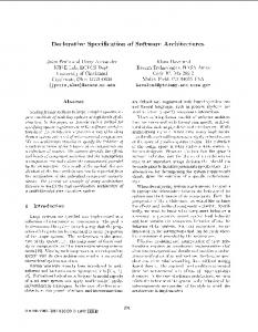
SoB Figure 1: Simplified diagram of a chemical B is poured into the tank until level2 is reached. This level corresponds to an overall volume of 500 gals. Then, "sol2" is turned off. When both ingredients are f.oured into the tank the temperature is raised to 300 C and the mixer is switched on for 20 min. During this time period the controller tries to keep the temperature around 300°C by turning on the heater each time the temperature drops below the 300°C and turning it off when the temperature exceeds the same value. At the end of the 20 min period the drain valve "soB" is opened and the tank is emptied. Then, soB is closed and the cycle is repeated. In Figure 2 a SFC description of this operation is depicted.
4.
REQUIREMENTS VALIDA TION OF THE SFC
In order to verify requirements of the specified control system, the HAS system shown in Figure 3 is derived by applying the above explained mechanism for mapping components of SFC to components of HAS. For example the actions of steps 1, 2, 3 and 4 of SFC are simulated by the respective single locations "idle", "h-I, "h-2"and "Fill-a", whereas step 6 is simulated by the pair of the locations "Fill-a 1" and "Fill-b". The return from the step "Fill-a" to the "h-I" step is mapped to a new location "t-I". In a similar way each one of the remaining steps is mapped to one, two or three locations of the HAS. In order to check if this automaton reaches a certain state, the external events and conditions which are generated by the controlled process and under which the described software is assumed to run, need to be defmed. This can be achieved by modeling each component of the process as another hybrid automaton which is synchronized
EXAMPLE
Let us consider the chemical reactor shown in Figure 1. Its operation under the control of an external controller is as follows . At the reactor start-up it is assumed that the internal tank temperature has been raised to the 90°C and then valve "soIl " is commanded to open. Ingredient A is poured into the tank and when the tank is filled up to the level 1, which corresponds to a 100 gal of A, the soil is closed and the valve "soI2" is turned on. Ingredient
109
L. ....
D ~
7
In Table I the actions associated with the steps in Figure 2 are listed. The HAS that is derived from this SFC by applying the bisimulation relationship of section 3 is shown in Figure 3.
g=O, h=O Emp-2
t----
(0 < h S; 100 ) Table I Step Actions
~
Step Number 2
h-I
t--
_(100 < h < 110) v (h
3
~
I 2 3 4 5
300)
6 7 8 9 10
h-2
t--
11
r.-(h > 90)J\(g < 100)
g h ta
4
-
tm kJ
r--- FilI-a
-Ch > 90) J\(g 5
6
+
(h ~ 90) J\ (g
h
~
8
dh=[ mintemp,maxtemp] where mintemp, the minimum rate of temperature increase maxtemp, the maximum rate of temperature increase
= 500)
FilI-b I
Mix-I
la=20
-
: the volume of ingredients A,B : temperature : clock of mixer : clock of the whole process : discrete variables
h < 90
'--
300
7
+-
-
Fill-b
t--
Initialize Heater -on Heater-off Open Soil Close Soil Open Sol2 Close Sol2 Start mixing Continue mixing Empty reactor Close sol3
The rates are specified as: dg=[minflow,maxflow] where minflow, the minimum flow rate of ingredient maxflow, the maximum flow rate of ingredient .
= 100)
Fill-al
-t-
Description
Table 2 Definition of variables
--90 < h S; 100 -
Action Mnemonic Idle h-I h-2 Fill-a Fill-al Fill-b Fill-b I Mix-I Mix-2 Emp-I Emp-2
Mix-2 Emp-I
+g=O Figure 2: SFC of the reactor control.
110
in
g=0 /\ h=O j=O /\ tm=O
g.=100 & h>=90
g=O 1351 g>=I00
h= 110 & g=O
k:=1
lIsI
h