1
Variable Guard Interval Orthogonal Frequency Division Multiplexing in presence of Carrier Frequency Offset Suvra S Das1,2 , Frank H. P. Fitzek1 , E. D. Carvalho1 , Ramjee Prasad1 1 Center for TeleInFrastruktur (CTiF), Aalborg University,Denmark. 2 Tata Consultancy Services, India. e-mail:
[email protected]
Abstract— The goal of this paper is to highlight the benefits of using variable guard interval (VGI) in Orthogonal Frequency Division Multiplexing (OFDM) based wireless local area network (WLAN) systems. An algorithm is derived and its performance merit for implementing VGI in the presence of carrier frequency offset is provided. OFDM system needs to maintain orthogonality among sub carriers, which may be lost due insufficient guard interval and carrier frequency offset (due to local oscillator mismatch and doppler effects). Static guard interval is usually kept large enough to tolerate worst case channel delay spread conditions, which in turn causes loss in efficiency of the system. The use of variable guard interval is expected to improve the system throughput. Since insufficient guard interval and carrier offset together cause orthogonality loss among sub carriers, the dynamic selection of guard interval in the presence of carrier frequency offset is considered in this work. Results are presented to analyze achievable gains. It has been shown that significant improvement in throughput is achievable by this scheme.
I. I NTRODUCTION Orthogonal frequency division multiplexing (OFDM) is being increasingly used as a basic enabling physical layer technology for high data rate wireless communication systems. Its long symbol duration provides capability to withstand multi path fading prevalent in wireless channels. Orthogonal sub carriers, capable of very dense placement, give support for high data rate communications. With flat fading on each sub carrier, it needs only a simple equalization architecture. Its probable use in future systems is also evident from the increasing research publications and inclusion of this technology into new and forthcoming high data rate wireless access standards [1], [2], [3] and research projects. Using guard interval (GI) between consecutive OFDM symbols is a common practice to overcome inter symbol
interference and maintain orthogonality between symbols. An inappropriate length of the guard interval (if less than the maximum delay spread of the channel impulse response) will cause inter symbol interference and inter carrier interference due to loss in orthogonality. It is important to note that carrier frequency offset also causes loss in orthogonality among the sub carriers [4]. The GI is implemented as a cyclic prefix (CP) or zero padded (ZP) [5]. The length of the GI is decided after channel measurements. It is several times the maximum channel rms (root mean squared) delay spread in the considered scenarios. Use of guard interval, which is an overhead, causes a loss in spectral efficiency of the system. Using a CP instead of ZP causes an additional wastage of energy on top of spectral efficiency loss. In IEEE 802.11a/g [1], as much as 25% of the useful signal part is the GI. Several measurements in open plan building [6], outdoor [7], for fixed wireless broad band [8], etc show that the local rms delay spread varies from few tens of nano seconds to few hundreds of nano seconds. Works in [9] and [10] express the closeness of the rms delay spread distribution to log normal distribution. Under such realistic environments, systems using fixed guard interval (GI) (chosen several times more than the maximum rms delay spread in the environment) force devices which experience smaller rms delay spread to use an unnecessarily large guard interval. Costly resource is wasted from network point of view and power is wasted from the device perspective, where battery life is also a major concern. This background motivates the use of variable guard interval (VGI). With variable guard interval, significant improvement in spectral efficiency can be achieved. An elementary form of this was attempted in IEEE 802.16a [2]. It has the provision for choosing the optimum guard interval by a base station. But once a base station (BS) chooses a guard interval, all subscriber stations (SS), in the cell
2
covered by the BS, will use the guard interval chosen by the BS. Effectively, there is only one guard interval (GI) for one BS or an access point. The proposal in this paper, is for simultaneous existence of variable guard intervals in one BS or access point. The rest of the paper is organized as follows. The system is described in Section II. The analysis of the achievable gains, and the derivation of the algorithm is presented in Section III. Simulation results are presented in Section IV. We conclude the paper in Section V followed by acknowledgements. II. S YSTEM D ESCRIPTION The focus of this paper is on WLAN environment similar to IEEE 802.11a which uses CSMA/CA type of access. For such systems, each transmission burst belonging to different devices may have different GI for the data portion, though the training sequence and the header OFDM symbol must have a fixed guard interval. This can be implemented in two ways. The subscriber station (SS) listens to transmission bursts from the access point (AP) to the other subscriber stations or may use the clear to send (CTS) from the AP to estimate the channel and decide the required guard interval. The SS can also use other feedback transmissions such as those used for adaptive modulation and coding (AMC) etc. The typical frame structure can have a training sequence derived from IEEE 802.11a with a fixed guard interval in the preamble (the training sequence), and a variable guard interval for the data portion. The length of the chosen guard interval can be indicated in some header (SIGNAL field in IEEE 802.11a/g systems). III. A NALYSIS A. Expected Improvement The reduction in loss can be derived to be Relative
Loss = K
τRM S − τrms τrms =1− KτRM S τRM S
(1)
where τrms denotes local rms channel delay spread;τRM S =max(τrms );τrms is the average rms delay spread. It is assumed that the guard interval in a normal system is taken to be K times greater than τRM S . In the system being proposed the relative gain is exactly equal to the loss as existent in current OFDM system. It has been found that in indoor as well as outdoor in certain situations as much as 80-90 % reduction in such loss can be achieved.
B. Derivation of Required Guard interval The sth transmitted OFDM symbol can be expressed from [4] Nf
−1 2 X 1 j2π k (t−sTs −Tg ) Xs [k]e Tf xs (t) = √ ΞTs (t − sTs ) Tf Nf k=−
2
where Tf is the duration of discrete fourier transform (DFT), k is the sub carrier index, Nf denotes number of sub carriers, Xs [k] is the modulated data symbol on the sub carrier, Ts is symbol duration which is the sum of Tf and the guard interval Tg . ΞTs (t − sTs ) is the gate pulse of duration Ts starting from t = sTs . After passing through the channel, the signal can be represented as, R τmax h(τ )xs (t − τ ) dτ + ν(t) (2) r(t) = 0 R τmax h(τ ) dτ 0 where τmax is the maximum tail of the channel impulse response and ν(t) is the noise component. The denominator of the above equation is the normalizing factor and can be set to unity. With perfect timing synchronization, but relative carrier frequency offset of ‘²’ the received OFDM symbol is rs (t) = r(t)e
j2πt T²
f
ΞTf (t − sTs − Tg )
The received sub carrier symbol can be written as Z Tf 0 k 1 0 0 −j2π T (t−sTs −Tg ) f Xs [k ] = √ rs (t)e dt Tf 0
(3)
(4)
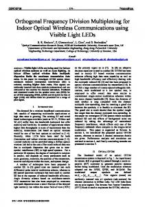
The Figure 1 shows the effect of previous OFDM symbol on the current OFDM symbol. The highlighted portion inside the circle introduces two effects. The first being the inter symbol interference on the desired sub carriers, while the second being the loss of orthogonality caused by inter carrier interference. Channel model of exponential power delay profile, with uncorrelated scattering using rayleigh distributed taps has been used for the derivation. Following such a model, τ0 = τm = τrms , where τ0 is the decay constant of the channel model chosen, τm is the mean excess delay and τrms is the rms delay spread of the channel. ([11] also shows linear relationship between τm and τrms ). First the effect of the previous symbol is considered. After a sequence of algebraic calculations the effect can be summarized as τ0 (5) EintfI ≈ E|Xs−1 [k]|2 e−Tg /τ0 , Tf where E|Xs−1 [k]|2 is the average power in the OFDM symbol, Tg is the guard interval duration, Tf is the DFT duration. This includes the effect of ICI and ISI caused by the interference of the previous OFDM on the current.
3
Previous Symbol
Current Symbol
GI
Fig. 1.
DFT Period
Effect of small guard interval
It can be said that for small values of carrier frequency offset, the influence of the previous OFDM symbol is dominated by the effect of insufficient guard interval. Next the effect of the insufficient guard interval and carrier frequency offset in the current (sth ) OFDM symbol will be presented. For the purpose of efficient computation, the region is separated in to two parts. One is the region within the guard interval while the other is the region beyond the guard interval. The result combining the total interference in this region is given below π 2 ²2 1 −Tg /τ0 + e } (6) EintfII ≈ E|Xs [k]|2 {(1 − e−Tg /τ0 ) 3 6 where ² is carrier frequency offset error relative to the sub carrier spacing. The energy of the useful part of the signal is Euseful ≈ ³ E|Xs [k]|2 sinc2 (π²){1 − e−Tg /τ0 }+ (7) ¶ τ0 2 τ0 2 ) + 2} e−Tg /τ0 {(1 − Tf Tf A criterion, such as, the signal to interference noise ratio be higher than the required measure, can be used to compute the required guard interval. To evaluate this, the signal power and total interference power must be computed. The useful signal power is already given in (7). It can be assumed that E|Xs−1 [k]|2 = E|Xs [k]|2 , SINR can be defined as the ratio of the total useful power to the total interference and noise power. If the required signal to interference noise power be set as γreq , then using the criterion SINR > γreq the condition on the required guard interval is derived as µ ¶ A Tg ' τ0 log (8) B where A = τ0 1 π 2 τ0 2 τ0 2 γreq { + − ²2 } − {(1 − ) + 2 − sinc2 (π²)} Tf 6 3 Tf Tf and π2 1 B = sinc2 (π²) − γreq { ²2 + } 3 γ It can be intuitively understood from B that extra SNR can be used to compensate for smaller guard interval. To
compute the required guard interval it was found that τ0 is needed. For this purpose, the channel impulse response is first estimated and then τm is computed. The required guard interval is computed using the estimated τm as τ0 . For computing the τˆm the following formula is used PL ˆ |h(n)|2 n τˆm = Pn=0 L 2 ˆ n=0 |h(n)| ˆ where h(n) is the estimated channel impulse response. Channel estimation schemes such as least square method followed by minimum mean square error criteria can be used. To reduce the effect of noise, especially at low ˆ SNR conditions, the length of the h(n) i.e. L is kept within known range. For wireless LAN like the IEEE 802.11a systems, either one or two OFDM symbols can be used for frequency domain channel estimation. The ˆ estimation error in h(n) amplifies as τˆm is computed ˆ g. from it, which is further used in the computation of T It has been seen that the variance of error in estimating the mean excess delay is within one sample for all channel models considered in this work. This implies such channel estimation schemes as described here can be relied upon for purpose as required here.
IV. P ERFORMANCE AND D ISCUSSION A. Simulation Environment Indoor wireless channel model from [12] is used. About one thousand instantaneous channels were generated, which were uniformly distributed between non line of sight (NLOS), rms delay spread of 50 to 250 nano seconds). Training sequence used for channel estimation, as described before. Bit error rates (BER), and block error rates (BLER) for block size of 1000 octets were recorded. Required guard interval was estimated using the algorithm developed in Section III-B. Channel was assumed static during channel estimation and transmission of packet. For system performance, rate 1/2 convolution channel coding has been used. For sub carrier modulation, quadrature phase shift keying (QPSK) has been considered. The required signal to noise was taken as 15 dB. The maximum tolerable relative carrier frequency offset has been kept at 0.04. B. Results Figure 2 shows the BLER performances for different amount of extra SNR (required SNR kept at 15 dB, while the system is run at the SNR value indicated in the xaxis of the figures). It can be seen that VGI OFDM performs as good as the normal OFDM system in terms of average BLER. A closer inspection reveals that for
4 0.26
1 VGI OFDM Normal OFDM
0.9
Probability (Throughput < abcissa)
0.24
Mean BLER
0.22
0.2
0.18
0.16
0.14
VGI OFDM Normal OFDM Mean VGI Mean Normal
0.8
0.7
0.6
0.5
0.4
0.3
0.2
0.1 0.12 15
15.2
15.4
15.6
15.8
16
16.2
16.4
16.6
16.8
17
SNR in dB
Fig. 2.
0 0.4
0.5
0.6
0.7
0.8
0.9
1
Throughput (Bits/s/Hz) at 17 db SNR
Mean BLER vs SNR
Fig. 4. CDF of throughput (using BER) at 2 db extra SNR. (Required SNR kept at 15 dB)
0.25 VGI OFDM Normal OFDM
system does not compromise on BLER performance in comparison to normal OFDM system. System throughput improvement are now discussed. Throughput improvement comes from the fact that, with VGI, there is a scope to use the optimal guard interval. In contrast, normal OFDM systems have to use a fixed guard interval and hence their throughput can be measured directly from their BLER. For a VGI system, having the same BLER as the normal OFDM system, the throughput, which can vary depending on the chosen length of guard interval, can be written as,
Mean BLER
0.2
0.15
0.1
0.05
0 15
16
17
18
19
20
21
22
23
24
25
SNR in dB
Fig. 3.
Mean BLER vs SNR
a slightly extra SNR region (required SNR is kept at 15dB) the normal OFDM system has only a little better performance than VGI. This may be due to the fact that inter symbol interference error floor starts setting in. It can be observed from the graph that about up to 2 dB of extra SNR can be permitted for no significant loss in BLER performance for the VGI system. Figure 3 shows the performance curves for VGI OFDM against the normal OFDM for extra SNR fixed at 0.3 dB higher than the required SNR level; i.e. at required SNR of 21 dB, the systems are actually run at 21.3 db and so on in the entire range. It is seen here that for the entire range VGI system does not give up BLER performance. From the above results it can be said that the VGI
η=
(1 − BLER) (Block Size in number of bits), Ts
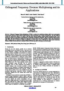
where Ts = Tg + Tf , the factor Tg varies for VGI while it is fixed for normal OFDM. Figure 4 shows the throughput curves (using BER statistics). The curves with respect to BER is given here so that they will be useful when considering a different packet length. It shows more than six percent improvement in the 10%outage throughput [13]. This implies VGI OFDM has shown better resilience to worse channel conditions. The mean throughput is improved in the range of about 14%. The most impressive result is that the maximum (almost same as the average) throughput of the normal OFDM is only the 5% outage throughput of the VGI OFDM system. This means that VGI OFDM will give more than the maximum throughput of the normal OFDM system 95% of time. The maximum throughput of the normal OFDM system is limited by the fixed guard interval. The VGI OFDM can reach a spectral efficiency of more than 95%, while that for the
5
multi path conditions. The VGI system is shown to have the more than average throughput of the normal ofdm system at least 80% of the time. Thus variable guard interval OFDM can be suggested for use in WLAN scenario to support improved maximum, mean and outage throughput as compared to OFDM systems using fixed guard interval.
1 VGI OFDM Normal OFDM Mean VGI Mean Normal
Probability (Throughput < abcissa)
0.9
0.8
0.7
0.6
0.5
0.4
VI. ACKNOWLEDGEMENT
0.3
The authors are grateful to TCS India for funding the project and to the WING lab members of Aalborg University for delightful discussions.
0.2
0.1
0
0
0.1
0.2
0.3
0.4
0.5
0.6
0.7
0.8
0.9
1
Throughput (Bits/s/Hz) at 17 db SNR
Fig. 5.
CDF of throughput (using BLER) at 2 db extra SNR
normal OFDM system under comparison is fixed at 80%. Figure 5 shows similar curve as above but in terms of BLER statistics. The improvement in the mean throughput is almost the same as above. The mean throughput of VGI is very close to the maximum throughput of the normal OFDM system. VGI OFDM system provides more than the average throughput of the normal OFDM system 80% of the time. The reduction in required guard interval also results in reduction in power usage. V. C ONCLUSION AND OUTLOOK In this work, the method of using variable guard interval (GI) for orthogonal frequency division multiplexing in wireless local area networks (WLAN) in presence of carrier frequency offset (CFO) in a multi path fading channel has been explained. Since CFO and insufficient GI together cause orthogonality loss among sub carriers thus jeopardizing the performance of OFDM systems, the dynamic selection of GI is considered in presence of CFO. An algorithm for estimating the required guard interval has been developed. In all situations a maximum relative residual carrier frequency offset of 0.04 has been assumed. It has been found that large reduction in loss of spectral efficiency and power is possible using this scheme (VGI OFDM). The performance of VGI OFDM is compared against a another OFDM system using a fixed guard interval. Mean throughput of VGI as compared to the normal OFDM shows an improvement in the order of 14%. The variable guard interval system also shows, about six percent improvement in outage throughput, thereby proving its better resilience to worse
R EFERENCES [1] IEEE Std 802.11g.-2003, “Part 11: Wireless LAN Medium Access Control (MAC) and Physical Layer (PHY) specifications Amendment 4: Further Higher Data Rate Extension in the 2.4 GHz Band,” IEEE, Tech. Rep., June 2003. [2] IEEE Std 802.16a-2003, “Part 16: Air Interface for Fixed Broadband Wireless Access SystemsAmendment 2: Medium Access Control Modifications and Additional Physical Layer Specifications for 2-11 GHz,” IEEE, Tech. Rep., 2003. [3] IEEE 802.20, “Mobile Broadband Wireless Access (MBWA),” Upcoming standard,http://grouper.ieee.org/groups/802/20/. [4] M. Speth, et al., “Optimum Receiver Design for Wireless BroadBand Systems Using OFDM - Part I,” IEEE Transactions on Communications, vol. 47, no. 11, November 1999. [5] Muquet, B.; Zhengdao Wang; Giannakis, G.B.; de Courville, M.; Duhamel, P., “Cyclic prefixing or zero padding for wireless multicarrier transmissions?” IEEE Transactions on Communications, vol. 50, no. 12, pp. 2136–2148, December 2002. [6] Rappaport, T.S.; Seidel, S.Y.; Takamizawa, K, “Statistical channel impulse response models for factory and open plan building radio communicate system design,” Communications, IEEE Transactions on , vol. 39, no. 5, pp. 794 – 807, May 1991. [7] Mohr, W, “Radio propagation for local loop applications at 2 GHz,” in Third Annual International Universal Personal Communications, Sept-Oct 1994, pp. 119–123. [8] Vinko Erceg, et. al., “A Model for the Multipath Delay Profile of Fixed Wireless Channels,” IEEE JSAC, vol. 17, no. 3, pp. 399–410, March 1999. [9] R. Cox, D.; Leck, “Correlation Bandwidth and Delay Spread Multipath Propagation Statistics for 910-MHz Urban Mobile Radio Channels,” IEEE Transactions on Communications, vol. 23, no. 11, pp. 1271–1280, 1975. [10] IEEE802.16a, “Channel Models for Fixed Wireless Applications: IEEE 802.16a-03/01,” IEEE 802.16a, Tech. Rep. IEEE 802.16a-03/01, June 2003. [11] Theoder S. Rappaport, “Characterization of UHF Multipath Radio Channels in Factory Buildings,” IEEE Transactions on Antenna and Propagation, vol. 37, no. 8, August 1989. [12] J. Medbo, H. Andersson, P. Schramm, H. Asplund and J.-E. Berg, “Channel models for HIPERLAN/2 in different indoor scenarios. COST–259,” EURO-COST,” Report, 1998. [13] A. Paulraj, et. al., Introduction to Space Time Wireless Communiactions. CAMBRIDGE, 2003.