ABSTRACT. This article presents the software and hardware implementation of a low cost and high performance image edge detection algorithm. This algorithm ...
International Journal of Computer Applications (0975 – 8887) Volume 91 – No.12, April 2014
VHDL based Hardware Architecture of a High Performance Image Edge Detection Algorithm Hanene Rouabeh
Chokri Abdelmoula
Mohamed Masmoudi
EMC Research Group, National Engineering School of Sfax, Tunisia
EMC Research Group, National Engineering School of Sfax, Tunisia
EMC Research Group, National Engineering School of Sfax, Tunisia
ABSTRACT This article presents the software and hardware implementation of a low cost and high performance image edge detection algorithm. This algorithm will be used as part of a complete vision based driver assistance system. The main challenge consists in realizing a real-time implementation of edge detection algorithm that contributes in increasing the performance of the whole system. The software implementation of the developed algorithm using MATLAB tool is discussed in this paper, as well as the hardware architecture developed using VHDL language. Test results for both implementations were presented and compared to other edge detection operators. Computational time and other features comparison have shown the effectiveness of the proposed approach.
General Terms Computer science, Image processing, VHDL
Keywords: Image processing, Edge detection, VHDL implementation, FPGA
1. INTRODUCTION In the last decades, the increasing use of vehicles and the complexity of road scenes have encouraged researchers to develop and design intelligent driver assistant systems. Many presented works in the literature have taken advantage from the rapid development of computer science and electronic system technologies. Most challenging problems in designing efficient driver assistant systems are the choice of the perception module and the development of robust and accurate data processing algorithms. In this context the presented work discusses the development and the VHDL based implementation of an optimized and high speed image edge detection algorithm. This algorithm is part of a vision based intelligent driver assistant system subject of our research activities. Edge detection is one of the most important image processing algorithms employed extensively in object recognition and image segmentation applications [1]. Many edge detection techniques have been used in the literature. Classical edge detection operators have been involved in various applications. Comparative studies of these classical operators were presented in researches [2 – 4]. Comparison shows that classical operators such as Sobel, Prewitt and others have good results but some disadvantages exist like sensitivity to noise. This drawback is more important for Gradient based operators. It was demonstrated in [3] that Canny operator shows performing results compared to other algorithms but with more computational time cost. To overcome these
problems researchers have tried to develop new edge detection techniques to reduce both computational time and complexity, and to improve the robustness and accuracy of this image processing task. In this way other edge detection approaches were focused on the use of cellular automata based techniques to achieve more efficient edge detection algorithms. The discrete model of Cellular automata and their simple formulation of parallel computation [5] present many advantages. In last years cellular automata is widely used. Approaches discussed in [6–10] have shown efficient results due to the main characteristic that consists in involving the neighbors of a pixel in the edge detection process. This property is not used in classical edge detection operators. The developed method in this work is a neighborhood based technique that doesn’t involve cellular automata rules. These rules should be determined carefully to obtain the desired results; a large time is required to fix the suitable rules to work with. A simple algorithm was developed based on the use of pixels neighborhood structure and efficient results are shown. Many hardware architectures were developed in the literature for edge detection algorithms. Parallel implementation of a 3x3 moving window based on shift registers were developed for Sobel operator in [11–12]. Canny operator based hardware architectures were also designed to reduce the computational time in [13–14]. An optimized VHDL based hardware implementation of the proposed edge detection algorithm is developed and simulated in this work. The remainder of this paper is organized as follows. Section 2 discusses the software implementation of the edge detection approach. Section 3 presents the VHDL implementation. Results are detailed in section 4. In section 5 results are discussed. A summary of the key points concludes the paper in section 6.
2. EDGE DETECTION APPROACH 2.1 Motivation This section presents the edge detection technique developed in this work. Image edge detection is an important processing task that facilitates the automatic road sign recognition system by specifying objects boundaries. The edge detection algorithm works on binary images. In this work the binary input images are obtained by the application of a red color segmentation operation that will be published in future publications. But also the proposed algorithm has been tested on binary images obtained by the conversion of RGB color images to binary images using MATLAB toolbox. Image edge detection is one of the most challenging image processing algorithms. Many studies were developed towards
37
International Journal of Computer Applications (0975 – 8887) Volume 91 – No.12, April 2014 improving the efficiency of the existing used operators. In fact classical operators like Sobel and Canny have shown efficiency in edge detecting, but results are influenced by the high sensitivity to noise of these operators. In addition to that the obtained edges are not very smooth and those operators don’t take part of the neighborhood of pixels. These operators show better results with the cost of computational time and complexity. To overcome all of these difficulties a new technique based on the use of a pixel neighborhood structure and a simplified formulation of the edge detection operation is proposed in this work.
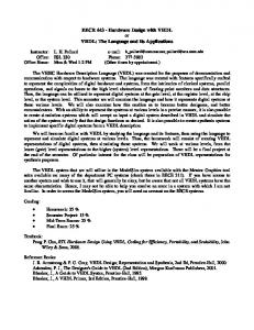
2.2 Edge detection algorithm The proposed edge detection method is based on the selection of the four adjacent neighbors of every pixel and calculating their average value using Von Neumann neighborhood structure [15]. A sequential operation is conducted to find for every pixel in an image the four neighboring values. Figure 1 shows the neighborhood selection for a pixel of coordinates (i, j) in an image of size HxW where H is the image height and W is the image width.
Fig1. Used neighborhood structure The average value of the four neighbors is calculated. Subsequently the difference value between the original pixel and neighbors average values is calculated. The new value of the pixel in the edge image will be decided according to the minimum value between original pixel and difference value. If this value is greater than zero, the new pixel value would be set to one, and would be set to zero in opposite case. The framework of the proposed method is presented in Figure 2. The software implementation of this method was developed using MATLAB tool and compared to Sobel and Canny based edge detection methods. Results have shown the effectiveness and robustness of the proposed method. The obtained results present more performance in detected edges that are finer than others and less computational time is used. Simulation results will be discussed later.
Fig2. Edge detection algorithm flowchart
3. VHDL IMPLEMENTATION OF THE PROPOSED METHOD This section describes the steps achieved in the realization of the VHDL based architecture of the proposed edge detection algorithm presented in sub section 2.2. The VHDL project was developed using QUARTUS II environment and simulated using ModelSim Altera tool. The edge detection method was developed and tested in MATLAB, and then was implemented using the VHDL language. Two files were created for this purpose, the first one describes the image processing scheme while the second one presents the test bench used for simulation. A text file containing the binary input image is also used to test the algorithm and to prove the efficiency of the proposed architecture. The overall hardware architecture structure is depicted in Figure 3 that presents the model structure of the developed edge detection algorithm implemented with VHDL language.
38
International Journal of Computer Applications (0975 – 8887) Volume 91 – No.12, April 2014 the outputs of this block are the four values: R (0), R (W+1), R (W-1) and R (2W). In the proposed edge detection architecture, pixels in the first row and first column respectively in last column and last row are processed using null boundary condition, for that some conditions are taken into consideration. These conditions will be discussed in the next sub section. Pixel (1, 1) is the first pixel to be processed. This pixel will be located in R (W) after W+1 clocks. The shift register cells are initialized to zeros values so when Pixel (1, 1) is located in R (W) the condition of null boundary is verified.
3.2 Pipeline implementation Fig3. Hardware architecture of the developed algorithm
The block diagram of this module is presented in Figure 5. The inputs are the four neighbors of a considered pixel outputted at every rising edge clock.
As shown in this schematic the system is divided into four blocks. Each bloc is designed to process a specific part of the edge detection system and will be explained separately. The input pixels data of the binary image are stored in a text file; a “Clock” signal is used to read these pixels continuously. “Enable” signal controls the edge detection processing operations. The “endofimage” signal is used to control writing to text file process.
3.1 Shift register neighborhood selection It is the first module of the architecture. As mentioned above, the input image data is a binary image obtained by the application of a red color segmentation method that will be published in future work. The proposed hardware architecture is used to generate the edge detection result. For this purpose, input image data is converted into one dimensional array and stored in a text file to be accessed and read pixel by pixel. As explained in subsection 2.2, the first step of the edge detection algorithm is the extraction of the four adjacent neighbors for every pixel, so the same operation should be applied serially for all pixels of the considered image. A hardware implementation of 3x3 moving window using three shift registers was presented in many works [11–12]. The presented architecture in this work was inspired from the idea of using shift registers but in this case one shift register was used. The size of this shift register should be 2W+2 where W is the image width. The data are read from the text file; one pixel enters in the shift register at every rising edge clock. Figure 4 shows the considered shift register.
Fig5. Pipeline implementation module This bloc is designed to realize the different steps of the edge detection scheme. The average value is obtained by the sum calculation followed by a division by four. This value is then used to calculate the difference value. As known a division by four means a multiplication by 0.25 to avoid dealing with real numbers, the sum is multiplied by the value 25; that is to say (0.25x100). And then when we calculate the difference between original pixel and this value we multiply the original pixel by 100 to obtain the exact difference value. The outputs of this bloc are “Abs_val” that presents the absolute value of the calculated difference and “Prod” is the product of original pixel by 100. A conditional loop is used to control the process of boundary pixels. For this purpose an internal counter is used to count the number of the processed pixel. Table 1 resumes the used conditions. Table1. Sum expression according to pixel position
Fig4. Used Shift register Figure 1 shows the four neighbors of Pixel (i , j) that must be accessed at the same time , so the entire image is scanned pixel by pixel and row by row, and at every rising edge clock a pixel of coordinate (i , j) is selected and the four neighbors are outputted. An identification between Figure 1 and Figure 4 demonstrates that at every rising edge clock Pixel (i, j) is located in R(W) , Pixel(i-1,j) in R(2W) , Pixel(i, j-1) in R(W+1), Pixel(i, j+1) in R(W-1) and Pixel(i+1, j) in R(0). So
Condition
Sum expression
Counter = W Counter = (H-1)xW+1 Counter mod W = 0 Counter mod W = 1 Others
R(0)+R(W+1) R(2W)+R(W-1) R(2W)+R(W+1)+R(0) R(2W)+R(W-1)+R(0) R(2W)+R(W+1)+R(W-1)+R(0)
From this table it is clearly noted that the first sum expression is used for Pixel(1,W), the second is used for Pixel (H,1) , the third is used for pixels in column W from Pixel(2,W) to Pixel(H-1,W) , the forth is used for pixels in column 1 from Pixel(2,1) to Pixel(H-1,1) and the final expression is used for all other pixels.
39
International Journal of Computer Applications (0975 – 8887) Volume 91 – No.12, April 2014 To achieve high speed architecture the pipeline structure is used. The pipeline divides the whole operation into simple operations. The complicated operation in this module is the sum operation. Using the pipeline implementation this sum is divided into three simple sums. As a result a high frequency operation is achieved and the effectiveness of this implementation contributes in increasing the performance of the whole architecture.
3.3 Edge image pixels generation module This module is presented in Figure 6; it achieves the final operation in the edge detection algorithm consisting in the determination of the minimum value between the “Abs_val” and the original pixel value using a comparison. And then the output value will be decided according to the minimum value. The pixel value in the edge image takes the value 1 if the minimum is positive and will be set to zero otherwise. A simple implementation of these two operations is done using a simple if - then clause.
Fig8. (a) Original Image 1
Fig8. (b) Original Image 2
Fig8. (c) Binary representation for two images
Fig6. Edge image pixels generation module
3.4 Write to text file module The last process in the proposed edge detection architecture is the writing process. This process is used to save the output results in a text file. The stored output image will be read from the generated text file and displayed using MATLAB software. And then this image is compared to the edge image generated using the software execution of the developed algorithm in MATLAB.
Fig8. (d) Edge images using proposed method
Fig8. (e) Edge images using Sobel operator Fig7. Writing to text block module
4. SIMULATION RESULTS 4.1 Software based simulation results The whole edge detection scheme developed in this work was firstly implemented using MATLAB software tool and tested for many binary images. These images are obtained using the red color segmentation algorithm but it was also tested on images obtained using other binarisation method. Figure 8 presents the software simulation results. Fig8. (f) Edge images using Canny operator Fig8. Software simulation results for two examples
40
International Journal of Computer Applications (0975 – 8887) Volume 91 – No.12, April 2014 We have also compared the proposed algorithm to Canny and Sobel operators on a binary image obtained using the MATLAB image processing toolbox and the threshold based image to binary conversion method. It was noted that the proposed algorithm is very efficient for edge detection scheme in general cases, Figure 9 shows the test results.
Fig9. (e) Edge image using Canny operator Fig9. Test on a binary image without red color segmentation Fig9. (a) Original image Table 2 presents elapsed time in seconds for the three image edge detection tests. It is shown that the developed approach in this work is very efficient according to low computational time cost compared to other operators. Table 2. Computational time comparison
Fig9. (b) Binary image
Proposed method
Sobel operator
Canny operator
Image 1
0.081352 seconds
0.390348 seconds
0.640442 seconds
Image 2
0.097543 seconds
0.495176 seconds
0.606765 seconds
Image 3
0.090566 seconds
0.377980 seconds
0.910670 seconds
4.2 Hardware simulation results The simulation of the VHDL implementation of the proposed algorithm is done using Modelsim Altera. The compilation summary for the Cyclone III EP3C120F780C7 FPGA device obtained using QUARTUS II environment is presented in Table 3. Table 3. Hardware resources Fig9. (c) Edge image using proposed method
Total logic elements 1,740/119,088 (1%)
Total memory bits 511/3,981,312 (