calls can be rejected if the user is on the telephone. Assistance of this ..... Segen of AT&T Bell Labs describes a system using video alone which allows, for ...
Video-Augmented Environments
A dissertation submitted for the degree of Doctor of Philosophy James Quentin Stafford-Fraser Gonville & Caius College University of Cambridge February 1996
To my parents, who taught me to explore, and to my wonderful wife Rose, who encouraged & supported me while I did so.
ii
Preface
Except where otherwise stated, this dissertation is the result of my own work and is not the outcome of work done in collaboration.
This dissertation is not substantially the same as any that I have submitted for a degree or diploma or other qualification at any other University.
No part of this dissertation has already been or is concurrently being submitted for any such degree, diploma or other qualification.
This dissertation is copyright © 1996 by J.Q.Stafford-Fraser
iii
Abstract
In the future, the computer will be thought of more as an assistant than as a tool, and users will increasingly expect machines to make decisions on their behalf. As with a human assistant, a machine’s ability to make informed choices will often depend on the extent of its knowledge of activities in the world around it. Equipping personal computers with a large number of sensors for monitoring their environment is, however, expensive and inconvenient, and a preferable solution would involve a small number of input devices with a broad scope of application. Video cameras are ideally suited to many realworld monitoring applications for this reason. In addition, recent reductions in the manufacturing costs of simple cameras will soon make their widespread deployment in the home and office economically viable. The use of video as an input device also allows the creation of new types of user-interface, more suitable in some circumstances than those afforded by the conventional keyboard and mouse. This thesis examines some examples of these ‘Video-Augmented Environments’ and related work, and then describes two applications in detail. The first, a ‘software cameraman’, uses the analysis of one video stream to control the display of another. The second, ‘BrightBoard’, allows a user to control a computer by making marks on a conventional whiteboard, thus ‘augmenting’ the board with many of the facilities common to electronic documents, including the ability to fax, save, print and email the image of the board. The techniques which were found to be useful in the construction of these applications are common to many systems which monitor real-world video, and so they were combined in a toolkit called ‘Vicar’. This provides an architecture for ‘video plumbing’, which allows standard videoprocessing components to be connected together under the control of a scripting language. It is a single application which can be programmed to create a variety of simple Video-Augmented Environments, such as those described above, without the need for any recompilation, and so should simplify the construction of such applications in the future. Finally, opportunities for further exploration on this theme are discussed.
iv
Acknowledgements
I am very grateful to Rank Xerox Research Centre (EuroPARC) for their support of this work, both in terms of finance and encouragement. Particular thanks go to Mik Lamming, Pierre Wellner (now at AT&T) and Mike Molloy for their enthusiasm, inspiration and patience, and to Michael Taylor for helpful & challenging discussions and for proof-reading. Peter Robinson deserves a great deal of thanks; he provided the right amounts of assistance and advice at exactly the right times – I could not have wished for a better supervisor. I would like to thank the University of Cambridge Computer Laboratory, in particular the members of the Rainbow graphics group, Gonville & Caius College, and the many colleagues and friends too numerous to be mentioned individually, who have contributed ideas, time, assistance or just caffeine. I am grateful to you all.
The names of all products referred to in this thesis are acknowledged as the trademarks of their respective owners.
v
Table of Contents
Video-Augmented Environments
1
Introduction Achieving Augmented Environments Terminology Thesis Organisation and Scope of Research
1 3 4 5
Example VAEs and related work
7
Introduction BrightBoard I In/Out Board The Virtual Window system Hand tracking and gesture recognition DigitalDesk The ALIVE system Software Cameraman & BrightBoard
VAE techniques Introduction Subsampling Motion Detection & Background Separation Thresholding Resolution Enhancement and Greyscale Thresholding
The Software Cameraman Introduction - The motive Doing it with software What constitutes interest? Selecting the area Selecting the eyepiece view Aesthetic Aspects of Camera Control Future Possibilities
BrightBoard Introduction – The whiteboard as a user interface A Video-Augmented Drawing Surface BrightBoard In Use How does BrightBoard work? Triggering Preprocessing Feature detection Analysing Executing Evaluation Future possibilities
Vicar: A VAE construction kit Introduction Vicar Scripting
7 7 11 11 12 13 13 14
15 15 15 16 23 25
30 30 31 32 32 32 33 35
36 36 37 39 41 41 42 42 49 50 51 52
54 54 55 55
vi
The Architecture Flow Control Frame transport in Vicar The sequence of source-sink interactions Vicar in use: The Software Cameraman and other examples In/Out Board monitor A User Interface for Vicar Future Possibilities Related Work
Conclusions and Future Possibilities Future Possibilities Summary & Conclusion
57 58 59 60 64 66 67 68 71
73 73 77
The BrightBoard Program Suite
79
The features used for BrightBoard’s symbol recogniser
81
The TCL source code for a simplified automatic cameraman
83
References
85
Table of Contents
vii
Chapter One
Video-Augmented Environments
Video cameras can now be produced, with controlling circuitry, on a single chip. Digital output reduces the need for expensive frame-capture cards, and it is reasonable to assume that simple cameras, being devoid of moving parts, will soon be a cheaper accessory for personal computers than keyboards, microphones, and mice. The possibilities for video-conferencing and other human-human interactions are obvious, but how might the ready availability of video sources enrich the way we interact with the machines themselves?
Introduction In the office environment the computer has traditionally been thought of as a tool, in the same way that a typewriter or Rolodex is a tool. It is an item employed by a person to accomplish a particular task. It is a very flexible tool, and can fulfil the roles of typewriter, Rolodex and calculator simultaneously, but the activity is generally initiated by a ‘user’, a term which succinctly describes the relationship. We might hope that the computer of the future would be more like an assistant than like a typewriter, that it would perform mundane tasks on your behalf when it sees they are necessary rather than always operating more directly under your control. Most computers spend the vast majority of their time idly waiting for humans, when they could be seeking out new business opportunities, trawling the world’s libraries for information relevant to a particular research proj ect, or simply answering the phone and throwing away junk mail. It is this vision which has fuelled the recent research into autonomous agentbased software. The extent to which users will be happy for a computer to make decisions on their behalf will depend on their confidence that it will make the right decisions. The more a secretary knows about your way of life, your preferred modes of work, how cluttered your desk is and when you are in a meeting, the more useful he or she can be to you. 1
Video-Augmented Environments The same applies to a machine, but the average personal computer has no knowledge of the world outside its box and has to be spoon-fed with information through its limited range of input devices. One approach to providing richer humancomputer interaction is that of Virtual Reality (VR). Users of VR don headmounted displays, earphones, gloves and microphones so that as many senses as possible can be used to draw them into an artificial, computer-generated world. Large amounts of money and effort are expended to create systems with higher resolution, better frame-rates, and tactile feedback so that this artificial world can resemble the real one as closely as possible. While VR certainly has valuable applications in specialist areas, the users still have to live, work, eat and sleep in the real world, and it could be argued that our lives will be richer if we can take the opposite approach: if we can make the computer an integral part of our world rather than making ourselves a part of the computer’s. Our world, after all, has infinite resolution, completely smooth motion and better tactile feedback than any artificial glove is able to give. This is the philosophy behind Computer-Augmented Environments; the desire to bring the computer ‘out of its box’ and give it more awareness of the world around, so that it augments and enhances daily life rather than attempting to replace it. Can we, for example, enable the computer to understand what we do in our offices rather than putting an impoverished ‘office metaphor’ on the machine’s screen? Can we centre computational power around everyday objects with which users are so familiar that they don’t think of them as a humancomputer interface? During work on the DigitalDesk [56], for example, (see Chapter Two), we experimented with ways of enabling the computer to recognise an ordinary pencil eraser, and using that as the means of deleting parts of an electronic image which was projected onto the desk. The motivation was simple: people already know how to use erasers, and will continue to use them for hand-drawn pictures. By augmenting the eraser’s capabilities we simply expand its scope of use. We neither detract from its abilities to erase pencil, nor require the user to learn a new tool. It would be naïve to pretend that the wide range of tasks we accomplish with our current user interfaces could all be performed equally well by similarly ‘projecting’ them into our physical world. Nonetheless, by building on the established abilities and expectations of the user we can gain in several ways: We can shorten the learning process. A user of the DigitalDesk might only need to be told, “You can use the eraser on projected drawings too”; a considerably shorter tuition than that required for the ‘delete’ process in many conventional software drawing packages. We can make user-interfaces more ‘physical’. Our bodies are designed to move in and interact with the physical world. When we limit their activity to sitting in a single chair, staring at a screen and Chapter One
2
Video-Augmented Environments moving a mouse, they tend to react with aching backs, tired eyes and Repetitive Strain Injuries. To provide some variety for our bodies, we deliberately choose to perform tasks in the physical world which could have been performed on screen. We print even short documents before reading them, we carry software around the office on floppy disks rather than distributing it on the network, and we look up and dial telephone numbers ourselves when the computer could do it more efficiently. There is something very satisfying about crumpling a sheet of paper and hurling it into the waste-paper basket which has no equivalent in the world of email. A user’s emotions can only be expressed by hitting the ‘Delete’ key a bit harder. We can save the user from unnecessary duplication of tasks in the electronic and physical worlds. At Rank Xerox EuroPARC (where much of this work has been conducted) a convention has arisen that an open office door indicates the occupant’s willingness to be disturbed, and a closed one should be seen as a deterrent. Whether consciously or otherwise, people will indicate intermediate levels of accessibility in the same way, for example by pushing the door almost completely, but not fully, closed. Experiments have been conducted [23] where machines, as well as colleagues, can take hints from such cues as these. The telephone bell is silenced after the first ring, for example, if the computer believes that a meeting is taking place. Incoming video calls can be rejected if the user is on the telephone. Assistance of this kind saves the user from tedious tasks, and is a step towards the concept of the computer as a ‘secretary’.
Achieving Augmented Environments There is an inherent difficulty in the goals of these ComputerAugmented Environments (CAEs). For computers to gain much understanding of the world around, they must be equipped with sensors to monitor it. These may be directly connected to the computer, or they may relay information to it via a communication medium such as radio or infra-red. The more sensors a computer has, the more complete will be the picture it can create of its surroundings and the activities of its users. However, the more sensors we embed in the environment, with their associated cables, batteries and power supplies, the more investment is needed to bring about our goal and the more intrusive the technology becomes, so frustrating the aim of an ‘invisible’ or ‘transparent’ user interface. The solution is to give the computer a small number of senses which have a broad scope of application and which operate remotely, i.e. without direct contact with the objects being sensed. The obvious candidate senses are vision and hearing, through the use of video cameras and microphones. Similarly, if the computer is to communicate with humans, then the analogous output systems are audio feedback and perhaps some projection facilities. Not only do cameras and microphones have a broad range of application, they can often be applied to more than one task at the same time. A single camera might monitor a whole room, and detect when the room is Chapter One
3
Video-Augmented Environments occupied, when a meeting is in progress, and when an overhead projector is being used, as well as recording the meeting. Out of office hours it could also function as a security camera. This thesis explores the use of video in the creation of ComputerAugmented Environments. Until recently the deployment of such systems in the average workplace would be limited by the cost both of cameras and of the computing power required to process video signals. However, manufacturing developments are making video cameras an economically viable alternative to more conventional sensors, and the typical office workstation is now capable of the simple image processing required for many of these ‘Video-Augmented Environments’.
Terminology It is worth taking a moment to clarify some of the terminology used in this area. The phrases ubiquitous computing and augmented reality have been used to describe approaches similar to the computer augmented environments discussed here, but with minor differences. Ubiquitous Computing Mark Weiser used the phrase ‘Ubiquitous Computing’ or ‘Ubicomp’ to denote his vision of a world where computers of various sizes are liberally scattered around the home and workplace. You jot down ideas on them as you would on a notebook, you sketch diagrams on them as you would on a whiteboard, and you wear them as you would wear a watch. These computers can talk to each other and to the stereo, the fax machine, the air-conditioning. Their ubiquity means that we think no more of them than we do of a stapler or a post-it note, and the communication abilities mean that we can take a computer to the task instead of having to bring the work to the computer [52]. While this model certainly depicts a closer integration of the real and electronic worlds, it relies on the assumption that the artefacts around us will increasingly be equipped with some computational power. This is certainly reasonable with respect to telephones and washing machines, but it may be some time before coffee cups, magazines and waste-paper baskets are equipped with batteries and infra-red communication links. The Ubicomp philosophy is not incompatible with VAEs, but the focus of VAEs is to add computational power to the devices we already use, rather than to create and exploit new varieties of computer. Augmented Reality The name ‘Augmented Reality’ has been used for systems which make use of see-through displays, especially head-mounted systems, to ‘project’ extra information onto the user’s view of the world. Feiner et al, for example, used a head-mounted ‘Private Eye’ display to overlay on the user’s view of a laser printer the information required to service Chapter One
4
Video-Augmented Environments it [12]. The name emphasises the contrast with ‘Virtual Reality’, and could sensibly be applied to a wider field, but has become so closely associated with this particular method of interaction that it was thought best to avoid it in the present work. Computer Augmented Environments ‘Computer Augmented Environments’ was the phrase chosen by the editors of the July 1993 Communications of the ACM as a generic heading under which to group the above and similar projects which “are united in a common philosophy: the primacy of the physical world and the construction of appropriate tools that enhance our daily activities” [55]. The present work deals with the subset of such tools which use video to monitor the physical world, and so the name Video Augmented Environments (VAEs) was chosen.
Thesis Organisation and Scope of Research Organisation The following chapter will describe some example Video-Augmented Environments and provide an overview of some related work. In Chapter Three there is a discussion of some of the problems commonly faced by VAEs and techniques for tackling them. Chapter Four describes a software-based ‘automatic cameraman’ which uses activity in one video stream to control the processing of another. Some of the lessons learned in the creation of the cameraman were important in the creation of BrightBoard, a system which uses video to augment the facilities of an ordinary whiteboard. BrightBoard is the focus of the thesis and is described in Chapter Five. We discovered that the construction of many such VAEs consisted chiefly in the plugging together of standard image-processing units, so in Chapter Six we discuss VICAR, an architecture for ‘video plumbing’ which allows simple VAEs to be created under the control of a scripting language. Finally, Chapter Seven draws some conclusions and describes possibilities for future developments. Scope The research described concentrates on practical applications of video to real-world problems using readily available hardware. In doing so it touches on a wide variety of topics within and on the borders of Computer Science, including image processing, pattern recognition and OCR, logic programming, human-computer interaction and document image understanding. A conscious decision was made at an early stage to explore a wide space of applications and not to be sidetracked into the minutiae, fascinating though many of these are. To evaluate some of these applications on today’s standard hardware, speed considerations have been paramount. Often a sophisticated algorithm has been rejected because a simpler one has been found to suffice, or because the performance requirements of interactive Chapter One
5
Video-Augmented Environments applications have forced us to sacrifice the elegant in favour of the practical. Goals In short, this work aims: • To explain why video is important and useful as a generic input device. • To examine some examples of Video-Augmented Environments and note techniques which were found to be useful in their construction. • Using these findings, to create a toolkit to simplify the building of similar applications in the future.
Chapter One
6
Chapter Two
Example VAEs and related work
Introduction In this chapter we discuss some examples of recent research which illustrate the application of relatively simple image processing to realworld video.
BrightBoard I BrightBoard explores the use of a whiteboard as a computer interface. Chapter 4 will describe the motivation for such a system and the final implementation, but here we will introduce the concepts by describing an early prototype, BrightBoard I. Background BrightBoard I had its origins in a simple whiteboard-recording program. A camera was suspended from the ceiling or mounted on a high bookshelf to give it a clear view of the whiteboard. The program would save an image of the board whenever it detected a ‘significant change’ (a concept not precisely defined at that stage). The current view was displayed on the screen, and a scrollbar allowed a user to scan earlier images and so to review recent activity on the board, recover previously erased information, and so forth. Experimenting with the system, users would frequently request extra features such as the ability to print images, email them, or pass them to another program for processing. Rather than expanding the system into a single monolithic application, the decision was made to simplify it into a whiteboard-based ‘control panel’ which could be extended through the use of shell scripts and external programs, and which would chiefly be operated from the board itself. The program was rewritten from scratch and named BrightBoard.
7
Example VAEs and related work
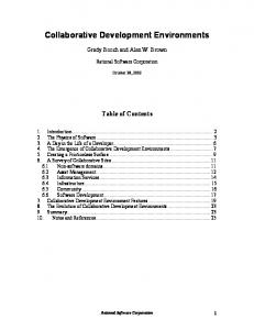
Figure 1. The user is presented with an image of the board
BrightBoard I - The user’s view The user, on starting the program, is presented with a thresholded image of the board which is updated every few seconds. He uses the mouse to select an area of the image which will be a ‘sensitive zone’, typically corresponding to a checkbox or other region marked on the board. Commands can then be specified which will be executed when changes occur within the zone (Figure 1 to Figure 3) The system detects when the zone becomes significantly darker (corresponding to a mark being made on the board) or lighter (when a mark is erased).
Figure 2. The user selects a sensitive zone and is prompted for information about it
Chapter Two
8
Example VAEs and related work Each may trigger a separate action, so checking a box might switch on the video recorder at the start of a meeting, and erasing the mark would stop the tape during confidential discussions or at the meeting’s end. The action can consist of any Unix shell command, and the user may request that all or part of the image be passed to the command via a temporary file.
Figure 3. The user enters details of commands to be executed
Some sample commands A simple whiteboard recorder might be created by selecting the whole area of the board as a sensitive zone, and specifying the command for both `lighter' and `darker' as: cp %s ~/board/
(The %s will be replaced automatically by the name of a temporary file containing the image). A more sophisticated version could be in a script called BBSave, triggered by a `Save' zone: #! /bin/sh echo STAMP=‘date +%y%m%d%H%M%S‘ cp $1 ~/board/$STAMP cat saved.au >/dev/audio
This saves the image using a filename derived from the current date and time, then uses audio (recorded speech) to announce that it has done so. The command executed by BrightBoard would then be: BBSave %s
A `Print' button might be implemented as: pgmtops %s | lpr
These ‘Save’ and ‘Print’ examples would generally act on the whole of the drawing area. In contrast, the following 'message zone' example Chapter Two
9
Example VAEs and related work uses just the area within the zone. A larger area is selected as the sensitive zone, and anything written there pops up on a secretary’s screen, using the image-viewing command ‘xv’: xv -display barbara:0 %s
BrightBoard I’s zone configuration data can be saved to disk and restored at a later date. The format of the file is such that it can easily be edited or generated by users or by other software; perhaps by a program which automatically detected the checkboxes. Discussion The biggest challenge for BrightBoard I was distinguishing a mark made on the board from the hand or head of a user. It used a very crude algorithm which detected the persistence of any change: if the zone becomes darker and remains so for several seconds then it is probably not a writing hand or the head of a passer-by. This is obviously not foolproof, and is achieved at the expense of response time; nonetheless, it made for quite a usable prototype with a ceilingmounted camera which rarely suffered from obstructions in its view. We will examine a more sophisticated ‘person detector’ in Chapter 5. The system also relied on the fact that the sensitive zones were in a fixed place in the camera’s image. Should the camera, board or checkboxes be moved, the system had to be reconfigured. Despite these limitations, a surprising amount can be done with a system which simply counts the number of changed pixels, and BrightBoard I was used for other prototype systems such as the In/Out board described below.
Chapter Two
10
Example VAEs and related work
In/Out Board
At EuroPARC, there is a board in the entrance lobby on which members of the lab place magnetic markers indicating whether they are in, out, or away on vacation. It is a very natural interface with which users feel comfortable and it requires almost no effort as one passes by on the way in and out of the building. People probably would not voluntarily use a system which involved a screen and keyboard, so this is a prime example of the advantages of ‘augmenting’ an existing physical user interface. Instrumenting this system could be very useful - when somebody arrives the computer could notify others who were waiting for them, or switch on their office lights and computer screens. Writing a videobased system to do this is a simple process – BrightBoard I has been used to demonstrate the idea, with no changes to the software being required. In this example system, users were sent email each day detailing their arrival and departure times and the number of hours worked. Adding computational features to such a mechanical, tactile system any other way, perhaps by replacing the magnetic markers with push-switches, would be considerably more complex and costly.
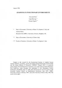
The Virtual Window system A simple video-analysis system has been used by Gaver et al to enhance the capabilities of a video-conferencing link [16]. A user’s head movements in a local office are monitored by a cheap dedicated camera and control the movement of the video-conferencing camera in a remote office. The metaphor used is that of a window onto the remote office, where by moving his head to the right, for example, a user can see ‘around the corner’ to the left.
Chapter Two
11
Example VAEs and related work
Normal Video Local User Moves to right
Virtual Window system
This provides a greater effective field of view and resolution, some semblance of 3-D, and allows for smoother interaction between users. The authors describe a simple example: “…it is common to hold something up to show a remote colleague, only to misjudge and hold it partially off-camera. Correcting the error usually requires explicit negotiation (“a little to the left…no, my left!”). The Virtual Window system allows the remote viewer to compensate for his or her partner’s mistake simply by moving, without requiring any explicit discussion about the mechanics of the situation.”
Chapters 3 & 4 will discuss in more depth the topic of tracking human movement.
Hand tracking and gesture recognition A variety of systems can be controlled efficiently by monitoring the position and gestures of a user’s hands. The Charade system, for example, used hand gestures to navigate through a hypertext system on a projected display [2]. Such systems have traditionally required the user to wear special gloves and position-sensing devices, but Jakub Segen of AT&T Bell Labs describes a system using video alone which allows, for example, the user to control a mouse-style pointer on the screen, or to ‘fly’ through a Virtual Reality-like environment, using hand movements and gestures watched by a camera [45].
Chapter Two
12
Example VAEs and related work
DigitalDesk
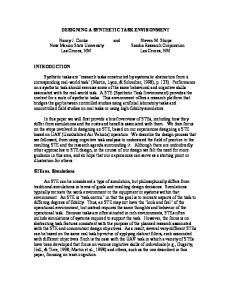
Figure 4. The DigitalDesk
The DigitalDesk [53,56] is a normal desk on which users can lay out their papers and leave their coffee cups, but it also has some characteristics of a workstation. Mounted above the desk are one or more cameras and a projector, which enable a computer to read paper documents placed on the desk, to monitor a user’s activity there, and to project images, documents and annotations down onto the desk. One of the interesting problems tackled by the DigitalDesk is that of calibrating the multiple input and output devices so that a mapping may be made between their individual coordinate systems.
A major goal of the project was the blurring of the boundary between paper and electronic documents. A number of prototype applications have been built which allow, for example: • copying and pasting of images and text from paper documents into electronic ones (the ‘PaperPaint’ application) • mathematical operations on numeric data contained in paper documents (‘DigitalDesk Calculator’) • language translation: pointing at words in a French document will cause an English translation to be projected alongside (‘Marcel’). The DigitalDesk is one of the most fully developed examples of Augmented Reality, and the reader is referred to the References for a more detailed description.
The ALIVE system ALIVE [34,35] stands for Artificial Life Interactive Video Environment and is the name of a system, created at the MIT Media Lab, which develops some of the ideas behind Myron Krueger’s VideoPlace [29]. A camera is fixed to the top of a large projection screen, and monitors a 16ft x 16ft area in which a user is free to move about. The image of the user is separated from the background and incorporated in another scene (typically a view of a room) which is then projected onto the screen in front of the Chapter Two
13
Example VAEs and related work user. Also included in the image are computer-generated animated creatures which move around the image under the control of autonomous agents. Their activity is affected by their interactions with one another and by the movement and gestures of the user. The result is a ‘magic mirror’ in which the user sees himself in a virtual world where he can, for example, bend down to pet an artificial hamster which then obligingly rolls over onto its back to be tickled. Other creatures can be sent away by pointing to the far side of the room, where they sulk until the user moves back towards them again. This system is great fun to use, but the technology required to make it work, in terms of both hardware and software, is substantial and rather specialised, and as such it is really beyond the scope of applications considered here. In addition, it is not so much a ‘Video Augmented Environment’ as an example of ‘Environment-Augmented Video’! However, ALIVE is of particular interest here because of the richness of interaction afforded by the use of a single video camera as an input device, and because it involves several simple techniques which can be useful in other systems. These include the following: • The user’s position in the 3D space is known, despite only having a single video source. The camera looks down on the user at an angle, and because the system knows the relative positions of camera and floor, and the fact that the user’s feet must be on the floor, it can deduce the users proximity simply by finding the lowest point in the outline of the user. This greatly increases the realism, because the user’s image then occludes, or is occluded by, parts of the virtual world depending on his/her position. • Simple gestures are detected by tracing the user’s outline in low resolution and finding the points of maximum convex curvature, which typically correspond to hands, head and feet. • Because the agents are modelled as animals, users are much more tolerant when they fail to understand or act on a command immediately – a common problem in VAEs!
Software Cameraman & BrightBoard In Chapters 4 & 5 we will discuss in more detail two further VAE examples, but first let us examine some techniques which are useful when constructing such tools.
Chapter Two
14
Chapter Three
VAE techniques
Introduction For most applications video has a very low signal-to-noise ratio when compared to other sensors; that is, the information in which we are interested forms only a small part of the information captured by the camera. The task of the application is often to reduce several megabytes per second of video data to a simple analysis like “there is/isn’t a person in the room”. In this chapter we discuss a few problems which are common to VAEs, and suggest some techniques for dealing with them. The issues are particularly relevant to BrightBoard, but they all have a much wider potential scope of application.
Subsampling The first ‘technique’ is so simple that it scarcely deserves the name, but it is sufficiently important to be worth mentioning first. Realworld video images contain a substantial amount of data, and if they are to be examined in any but the simplest of ways, a reduction in the resolution of the image often allows the single largest speed gain. Stephen Smith [48] points out that a second of digital video typically contains more information than the complete works of Shakespeare. An application will often have no need of a high-resolution image at all. In other cases, certain parts of the analysis can profitably be done at low resolution. Later chapters will describe how BrightBoard, for example, uses a 40x30 image to detect whether users are obstructing the view of the whiteboard before capturing a 740x570 image for detailed analysis. The number of pixels to be analysed in the ‘idle’ monitoring state is reduced from 420,000 to 1200, allowing a great improvement in response time, and/or a reduction in workstation load.
15
VAE techniques
Motion Detection & Background Separation VAE applications, in general, are interested in movement and change within a video image. Sometimes we wish to analyse the movement itself, as in the software cameraman described later, sometimes we just wish to know that movement has occurred because it is a trigger for something else, and sometimes we wish to avoid situations where change is occurring e.g. if we wish to capture whiteboard images without any humans in the way. Often it is human movement which is of interest – people in an office, hands on a keyboard, crowds on a station platform – but other things we might wish to monitor include pages emerging from a printer, documents moving on a desktop, or cars entering and leaving a parking lot. The common factor in all these situations is that movement occurs against a relatively stable background. ‘Background separation’ techniques aim to detect components of the image which are not part of a stable ‘background’ and so may be of interest. Movement, colour and intensity The majority of visual occurrences which attract our attention are due to changes in luminance; variations in the brightness of particular areas of the visual field [18]. These may be: • direct changes in intensity due to a light source variation, for example from a flashing warning light, or the flickering of a flame. • intensity changes caused by movement. The algorithms described here assume that the images captured are greyscale and not colour. The human visual system is more sensitive to changes of intensity than to changes of colour and the movement of objects is seen primarily by the difference in intensity between them and their background, rather than by chromatic variations [33,36,37]. In addition, monochrome cameras currently offer better image clarity for a given price than their colour counterparts, and so are perhaps more likely to be used in VAEs. We will therefore concentrate on monochrome, but it is worth noting that much important colour-based work has also been done. Ueda et al, for example, have impressive demonstrations of video segmentation based on chromatic analysis of real-world video [51]. Not all motion can be detected by changes in intensity. Horn & Schunck [25] point out that a rotating sphere with no surface markings causes no temporal changes in image intensity, despite the presence of real-world motion. Related to this is the ‘aperture effect’: if an unmarked object is viewed through a smaller aperture (e.g. a pencil seen close-up but through a key-hole) then only the component of motion perpendicular to an edge can be detected. Such situations rarely occur in the real-world applications considered here, however, and it should be noted that the human visual system could not detect motion under such conditions either.
Chapter Three
16
VAE techniques Differencing The simplest way to detect movement is to compare each captured video frame with its predecessor. At each pixel position, the magnitude of the change in pixel values is calculated, and any movement will generally cause significant values to be recorded. See Figure 7 (C). There will always be minor pixel differences between two live images even when the scenes appear identical to the naked eye. These are the result of such things as: • small variations in daylight illumination • the slight flicker of electric lighting • vibration induced e.g. by the fans of nearby equipment • the electronic limitations of the camera and frame grabber • electrical noise induced in the video circuitry. Many of the above can be eliminated by ignoring changes below a certain threshold, and unconnected single pixel changes. Differencing is simple, fast, and often supported in hardware. The chief limitations are as follows: • If the frame rate is high relative to the speed of any movement, there may be insufficient change between frames to allow much analysis. • If the frame rate is low, then the position of fast-moving objects will be sufficiently altered between frames for differences to occur in two distinct areas: where the original location has reverted to the background, and where the background has been obscured by the object’s new position. This is illustrated in Figure 5. There is no easy way to distinguish between the two areas, and this is a problem if we wish to detect the position of the moving object. It would be useful, therefore, to have some idea of what constitutes the background, so that we can detect changes relative to that, instead of merely detecting changes.
Chapter Three
17
VAE techniques
Figure 5. Inter-frame differencing. The frames in the second row show the differences between those above them in the first row.
Initial frame capture Some applications form a concept of the ‘background’ by requiring the equivalent of a ‘white balance’ setting – when the system is started, a frame is captured which is taken to be the ‘background’ and later frames are compared with it. Providing a clear view for the camera can be difficult: the author once used an office-monitoring system which required the user to crawl under the desk before clicking the mouse button so as not to appear in the image! Nonetheless, this is a reasonable approach for systems which are only expected to run for a short period of time. Longer-running applications have to cope with the fact that the ‘stable background’ is not in fact stable. Suppose we are monitoring activity in an office: After a while somebody enters through the open door, moving it slightly in the process. She sits down at the desk, moves a coffee cup to read some papers underneath, then stands up and leaves, taking the documents, switching off the desk light, and leaving the office chair in a slightly different position. A patch of sunlight moves slowly across the floor...
Many changes have occurred since the capture of the initial frame, but we do not wish to continue registering them indefinitely. We are monitoring activity, and as the office is now empty, activity has ceased. The program’s concept of the background must therefore be allowed to change slowly over time.
Chapter Three
18
VAE techniques Running Video Averages One way to construct an evolving ‘background’ frame is to use the average pixel values of the N preceding images. Any slow change that occurs in the background of the image, such as variations in the lighting of a room due to the sun’s movement, will gradually be incorporated into this average frame. Fast movements will still be visible when comparing it to a newly-captured image. A piece of furniture which is only moved occasionally, for example, will be detected when moved, but will rapidly fade into the background thereafter. Unfortunately, to average the N preceding frames necessitates keeping the last N frames in memory, which may not be practical for large values of N. We therefore use an approximation to a true average which only requires the current frame and an ‘average’ frame to be stored. When a new frame arrives, each pixel of the ‘average’ frame is recalculated as:
N −1 1 (newvalue) + (oldvalue) N N If the pixels do not, in general, change very fast, this is a good approximation. The most recent value still forms the same fraction of the result as it would in a true average, but the relative weight of past pixels decreases exponentially over time, rather than remaining constant until discarded. We call this system a Running Video Average (RVA) of length N. For performance reasons, we use integer arithmetic and make N a power of 2, which enables us to use bit-shifting instead of multiplication & division. The formula for the new value of a background pixel then becomes: (newvalue + (oldvalue > x
where 2x = N.
Chapter Three
19
VAE techniques
A. The Current Frame
B. An RVA of length 4
C. An RVA of length 256
Figure 6: Sample ’Running Video Averages’. The user arrives in the room, sits down, and starts typing. These frames were grabbed simultaneously. Note that the user’s hands and head are blurred in image B, but most of the body is crisp. The movement of the right hand, in particular, from keyboard to mouse can be seen. Subtracting image B from image A would highlight the quickly-moving areas. Image C is a general background view of the room, and subtracting image C from either of the other images would reveal anything that had moved within the last few minutes. A very faint outline of the user can be seen in image C. The longer he stays there, the more he will be considered part of the background.
Choosing the length of the RVA allows us to select the type of movement which interests us. The longer the RVA used, the more slowly changes to the scene are incorporated into it. (Figure 6). RVAs have been found to be a useful method of detecting motion. Some experimentation is needed in any new application to choose appropriate RVA lengths for the motion to be analysed and the frame rate likely to be achieved. It can be advantageous to maintain several RVAs of different lengths, so that detection of movement can be followed by further analysis. A room-monitoring system might detect motion near a desk and report, in effect: “There is something here which is not part of the stable background (long RVA) but there has been a lot of activity in this area recently (which appears in a short RVA).” Masked Running Video Averages As a final development of this theme, we consider the problem of periodic noise in particular areas of a video image. This is caused by the movement or changing intensity of items which we wish, never the less, to consider part of the background. In a home or office environment, examples include: • flickering monitors and TV screens • fluorescent lights • rotating fans • window blinds swaying in a breeze
Chapter Three
20
VAE techniques • reflections of any of the above To reduce the effect of such items, we can employ a modified combination of the Initial Frame Capture and Running Video Average methods described above. At startup, we capture a number of ‘background’ frames at approximately the rate we expect to capture them during the application. From these we calculate the mean and standard deviation of the values at each pixel position. The mean values are used to initialise the RVA frame. The standard deviations are combined with a global threshold value to give a threshold which is specific to that pixel position. We call this resulting image the ‘mask frame’ because it can be used to ‘mask out’ areas where varying pixel values are expected as part of the background. In capturing the background frames, it is advisable to introduce a random variation in the interframe delays, to reduce the likelihood of statistical anomalies caused by any periodicity of changes in the view. The value of the ‘mask’ for pixel (x,y) is
mxy = T + αs xy where T is a global threshold, α a calibration constant, and sxy the standard deviation of pixel values at (x,y). Within the application, when a captured frame is compared to the RVA frame, a significant change is only deemed to have occurred at any pixel if the magnitude of the change is greater than mxy at that pixel position. This system, which we call ‘Masked Running Video Average’, or MRVA, has proved useful in both the Software Cameraman (described in Chapter 4) and in the triggering module of BrightBoard (Chapter 5). Sample output can be seen in Figure 7. The more sophisticated a model we try to build of the background, the more we discover circumstances which defeat it. The ‘mask’ in our MRVA, for example, is unchanging. It embodies the variations in the background which were occurring during the capture of the initial images, but if somebody turns on a monitor or a ceiling fan thereafter, then new patterns of change will be seen for which the system has not been prepared. In this case the MRVA performs no better (and no worse) than the RVA. Of course, if somebody demolishes the building, the system will not be prepared for that either; at some point we must decide on a degree of permanence which makes the concept of a ‘background’ meaningful. It could be argued that the mask should also evolve over time, by basing it on a running average of difference frames, for example. A decision then has to be taken about the length of that average in addition to the length of the background RVA. For our tests in an office environment, which seldom ran for more than a couple of days, the evolving mask has not been necessary, but it might be more so in a permanently-installed and longer-running system, or in other application areas.
Chapter Three
21
VAE techniques
A. This is the background scene...
B. ...and we are interested in movements of the user.
C. Simple differencing between A and B will show the flicker of the screen as well as the arrival of the user.
D. Using a MRVA, the screen flicker is almost completely removed, while the user remains visible.
Figure 7: Masked Running Video Average
Further thoughts The biggest assumption we have made here is that the camera is stationary. These techniques will be of little use in situations where the background or the lighting is constantly changing. Techniques based on ‘optical flow’ can be used to analyse motion in a broader range of situations, including those where several moving objects are observed by a moving camera, but despite many developments since Horn and Schunck’s original work [25], optical flow algorithms tend to be iterative processes operating on a large number of pixels and therefore computationally very expensive. They are also rather sensitive to noise, particularly in the case of highly textured surfaces.
Chapter Three
22
VAE techniques This can lead to unexpected results at the pixel level, making the higher-level analysis of motion in the image more difficult. More sophisticated motion-tracking techniques are also available in situations where a mathematical model of the object being tracked can be created. Gee & Cipolla [17], for example, describe a noise-tolerant human face tracker which projects the current expected positions of facial features back onto the image and uses these as a starting point for feature detection. Readers are referred to the extensive literature in the robotics and computer vision community for details of further movement-analysis algorithms. The focus of this research is on simple VAEs which could be constructed quickly and deployed in a typical workplace using the hardware likely to be available there. More expensive algorithms and those targetted at narrower problem areas are therefore beyond the scope of this thesis.
Thresholding Thresholding is a common problem for VAEs. Several recent videorelated projects at EuroPARC have concentrated on the processing of images of documents. The DigitalDesk [55], DigitalDrawingBoard [6] and BrightBoard (Chapter 5) captured them from a desk, a drawing board, and a whiteboard respectively. Most documents consist chiefly of black (or dark) text on a white (or light) background, and there are many occasions when we wish to restore the captured greyscale image to this state, perhaps because: • we wish to store the image more compactly. • we wish to incorporate the captured image in an electronic document, and so wish the black and white levels to match. • we wish to pass the image to an OCR engine or some other process which requires a clear distinction between text and background. Document images captured from real-world camera sources typically have large variations in lighting levels across the image and between images captured at different times. The human visual system compensates very effectively for spatial and temporal variations, but a computer needs to be told how to do so. In whiteboard images captured for BrightBoard, for example, it is not unusual to find that the ‘black’ pixels in one part of the image are lighter than the ‘white’ pixels in another part. We often need to threshold images just to standardise them across time and space. There are many ways of performing thresholding and any textbook on image processing will have a section on the subject. The problem can be briefly summarised as follows, and for a more detailed discussion the reader is referred to Wellner’s well-illustrated description of the problems encountered in thresholding images for the DigitalDesk [56]. Under ideal lighting conditions, the ‘white’ and ‘black’ pixels in the image would each cover a limited range of values and would appear as Chapter Three
23
VAE techniques two clear peaks in the image’s histogram. In practice, the wide range of values for each of the two types, and the small number of black pixels relative to white, mean that the black peak is lost in the noise of the white. There are many sophisticated thresholding methods available to tackle these problems. For example, we can attempt to solve the former by examining only points near the black/white boundaries, thus giving a better balance of black and white pixels (Gonzales & Woods [19]), and the latter by dividing the board into tiles, finding local thresholds suitable for the centre of each tile, and then extrapolating from these centres to find suitable threshold values for intervening points (Castleman [8]). Another option is to model the background lighting level by trying to fit a polynomial B-spline surface to the lighter pixel values, a method suggested (though not described in detail) by Ballard & Brown [1]. Unfortunately, these methods are rather too slow for an interactive system on our hardware, so we use an adaptive thresholding algorithm developed by Wellner for the DigitalDesk [54]. This involves scanning the rows of pixels one at a time, alternating the direction of travel, and maintaining a running average of the pixel values. Any pixel significantly darker than the running average at that point is treated as black, while the others are taken to be white. To incorporate some vertical stability, the threshold actually used at each position in a row is the mean of the running average calculated there and the running average used at that position in the previous row. Many questions may be asked about the theoretical basis of this algorithm. How is the running average initialised? Why this arbitrary difference between horizontal and vertical, when lighting variations honour no such distinction? In the final analysis, of course, there is no universally appropriate thresholding algorithm, because there is not always Figure 8: A watermark background poses an interesting thresholding problem an unambiguous ‘ideal’ result. How should we deal, for example, with text printed over a watermark background? (Figure 8) How can one analyse the background lighting on a page which consists chiefly of colour photographs, or which is subject to sharply-defined shadows? There has to be some selection based on the task in hand, and the conditions likely to be experienced. Wellner’s simple algorithm works remarkably well in cases where the image is known to have small areas of dark on a light background, such as we find in the typical printed page and on a whiteboard, and it only involves a single examination of each pixel. It is this algorithm which has been used for BrightBoard. Chapter Three
24
VAE techniques
p+q 2
p
q
q+r 2
p+s 2
p+q+s+t 4
q+t 2
q+r+t+u 4
s
s+t 2
t
t+u 2
original pixels
r
r+u 2
u
generated pixels
Figure 9. New pixels are generated between the original ones by averaging the grey levels of the nearest originals
Resolution Enhancement and Greyscale Thresholding A disadvantage of thresholding a greyscale (typically 8-bit) image to produce a single-bit-deep bitmap is that much potentially useful information is discarded. The antialiasing effect of the grey levels gives the image a higher apparent resolution than it actually has, and thresholding reveals the true limitations by making diagonal lines ‘jaggy’. The image can be improved by enhancing the resolution artificially using the information contained in the grey levels. A simple way to achieve this is through linear interpolation as shown in Figure 9. New pixels are generated between the original ones by averaging the grey levels of the nearest originals, to create an image with twice the resolution in each axis. The thresholding process will then produce a higher resolution result. This may not, in truth, be closer to the original document at which the camera was pointing, but given the nature and source of the images it is likely to be so, and almost always produces a better looking result. The thresholding and any further processing will, of course, take longer, having four times as many pixels to analyse. A sample output of this algorithm is shown in Figure 10.
Chapter Three
25
VAE techniques
Original image (shown double size)
Original image after simple thresholding (shown double size)
Resolution-doubled image
Resolution-doubled image after simple thresholding
Figure 10. The resolution-doubling algorithm - sample results
An alternative approach, if the aim is to incorporate the image in an electronic document which has a white background, is to keep the greyscale information but normalise the background to white. If, at each pixel position, we can form an idea of the grey level representing white, we can adjust the pixel by the difference between this value and true white. This ‘white-level balancing’ gives a greyscale image, maintains the antialiasing, but also allows a white background. An additional bonus is that some representation of grey levels other than black and white is preserved, so we can tell when parts of the image have been drawn in a different colour. To estimate the white value at any pixel we can use the methods outlined for thresholding in the previous section: local histogram analysis, edge analysis, modelling of the lighting levels, or a simple running-average. The problem is more difficult than thresholding, because we wish to ascertain the actual value of ‘white’ where we previously just needed a threshold somewhere between ‘white’ and ‘black’. However, we also have an additional constraint: nothing can be lighter than the white background. Whenever we find a pixel which is lighter than our
Chapter Three
26
VAE techniques current estimation of the background we know that the background value must be wrong and should be lightened. One approach is simply to reset the background value to this new, lighter pixel value. However, it was found that images captured from the whiteboard contained a certain amount of electrical ‘ringing’ at sharp black/white transitions. The following graph shows the values of pixels in a horizontal line taken from Figure 12A, through the words “All the world’s”.
180 160 140 120 100 80 60 40 20
649
622
595
568
541
514
487
460
433
406
379
352
325
298
271
244
217
190
163
136
109
82
55
28
1
0
Figure 11. Pixel values against x-coordinates for a horizontal line taken from Figure 12A
The gradual lightening of the background is obvious, and the deep valleys correspond to the black strokes of the writing. On either side of these valleys are small peaks which are electrical, not image, artefacts. They can be seen in Figure 12 (A) as a ‘silver lining’ around the characters. Using the peak values to set the white value would cause the true white to appear too dark. We reduce this effect by adjusting the white value in the direction of lighter pixels, but not by the whole amount of the difference. Shortlived peaks are thus damped out to some degree.
Chapter Three
27
VAE techniques On this basis, then, we can propose the following ‘running average’ algorithm which is a modified version of Wellner’s thresholding method: for each row of the image: traverse left to right or right to left (alternately) and for each pixel: /* Adjust the evolving background */ background = (background * (N-1) + pixel) / N /* If the current pixel is lighter than the background, then move faster towards it (M is smaller than N) */ if pixel > background: background = (background * (M-1)+ pixel) / M /* Adjust pixel value so that the current idea of the background, or anything lighter than it, would be white */ newpixel = int(pixel + (maxval-background)) if newpixel > maxval: newpixel = maxval set pixel value to newpixel
The values N & M can be adjusted depending on the situation, but values of N=80 and M=2 seem to work well for a variety of images. The bit-shifting optimisations described in the thresholding section can also be applied if M and N are powers of 2. For an 8-bit whiteboard image the number of grey levels remaining after this process is typically only 16 or so, and the output will generally be normalised (contrast-stretched) to produce a useful result. An alternative but much more expensive approach is to use a median filter on the image to produce a background which can then be subtracted from the original. Sample output for both methods is shown in Figure 12. The next two chapters describe in more detail applications which make use of these techniques.
Chapter Three
28
VAE techniques
A. Original image
B. Differencing from a background created with a median filter of radius 16.
C. Using the ‘running average’ algorithm described . Figure 12. Grey level 'thresholding'
Chapter Three
29
Chapter Four
The Software Cameraman
Introduction - The motive It has been the tradition at EuroPARC to videotape the weekly lunchtime seminars. These are generally informal talks given by visitors to the lab, who use a variety of visual aids to illustrate their points: videos, miscellaneous gadgets, whiteboards, overhead projectors and computer displays. The camera used for recording the meetings stands on a tripod at the back of the room; it often has no human operator, and so covers a wide field of view to ensure that all of the action is captured. There are more reasons for this than simply the lack of volunteer camera operators. We have found that speakers who are happy to talk to a roomful of people containing an inconspicuous camera are less comfortable when their every move is being tracked by a human cameraman. An unfortunate consequence is that the important detail is often lost; the writing on the whiteboard, the demonstration video, the expression on the speaker’s face cannot be seen clearly on the final recording. Even overhead projector slides are often unreadable. This is chiefly due to the limits of the resolution, but the diversity of light levels also plays a part. If the camera is zoomed in on the OHP screen or a computer monitor then the automatic iris compensates for the brightness of the image, but when viewing the whole scene the OHP screen is generally a blaze of white while the speaker is lost in the shadows. Imagine a camera under the control of a computer, which would try to decide which parts of the image were likely to be of interest, and would direct the camera towards them by means of a motorised pan/tilt/zoom unit. In this chapter we describe a prototype softwareonly system, which could never be as good as a human operator, but which can produce a more useful video record than a stationary camera alone.
30
The Software Cameraman
Doing it with software The software cameraman was developed as a model with which to explore the concepts. Rather than having actual mechanical control of a camera, the system selects the interesting part of an incoming video image and scales it to a fixed size. This gives the ‘eyepiece’ view of an imaginary camera which is remarkably convincing, and which allows different algorithms to be tested without the potential problems of experimental hardware. (See Figure 13)
The program chooses the interesting part of the incoming video image, selects a surrounding 4x3 view...
...and scales it to fill the eyepiece
Figure 13: The Software Cameraman
This system of expanding & shrinking a section of the image does, of course, suffer from loss of resolution when the camera is ‘zoomed in’, but there are many occasions when this is not a problem or when low resolution is enforced for other reasons. Commercially available video systems such as QuickTime have tended to use small video frames (typically 160x120 pixels) to increase the frame rate available from given hardware and reduce storage requirements. Consider the production of a QuickTime movie. A cheap frame grabber might have a resolution of 640 x 480 pixels, so the creation of suitable images entails discarding 93.75% of the available pixels. This prototype system could be used to produce a movie of a meeting, automatically selecting the areas to discard. We simply set the eyepiece size to 160x120, and the program finds the most interesting parts of the meeting to occupy those few valuable pixels which remain. An alternative application might be the Virtual Window system [16] described in Chapter 2. Gaver et al used a similar but rather simpler algorithm which analysed a user’s head movement in a local office and used it to control a camera in a remote office which was providing the source for a video-conferencing link. Chapter Four
31
The Software Cameraman
What constitutes interest? In most situations we are interested in the humans visible in an image and these are almost always moving, whether consciously or not. The cameraman program, then, deems those areas to be the interesting ones where movement is occurring or has occurred in the recent past. The Masked Running Video Average, as described in the last chapter, was developed originally for this application, and allows us to distinguish human or similar movement from periodic noise occurring in the background. We use a low-resolution (60x40) MRVA to analyse the movement in the camera’s image.
Selecting the area Given a new ‘difference’ image created from the MRVA, how do we decide which area to view? First we find the rectangular ‘interest area’ which encloses the difference points having greater than a specified ‘squelch’ value, i.e. the area in which significant changes are occurring. Then, provided more than a certain number of these points have been detected, we adjust the current viewing area based on this new interest area. The eyepiece has a 4x3 aspect ratio, so the object is to come up with a four-by-three rectangle which includes the interest area, but the way in which we do this affects how smooth the ‘camera movement’ will be, and how comfortable the resulting output is to watch.
Selecting the eyepiece view At present the cameraman can operate in any of 4 ‘intelligence’ modes, each of which has a different method of choosing the viewing area: • Naïve - The viewing area is the smallest 4x3 rectangle within the overall frame which encloses the area of interest. • Slow - Each corner of the viewing area moves one quarter of the way from its previous position to the new position that would be calculated by the ‘Naïve’ mode. This acts as a damper on sudden movements and false triggers. • Heavy - This is more closely modelled on a real camera. The viewing area has a mass, and is acted on by a force which accelerates it towards its new position. There is a damping factor which decelerates it. • Algorithmic - This is based on the slow mode, but movement of the viewing area is constrained by certain rules which attempt to impose some order and reduce the possibility of sea-sickness amongst viewers. While intuition suggests that the ‘Heavy’ mode should be the right way to do it, because we are used to seeing the output from real cameras with real mass, there are several parameters which must be Chapter Four
32
The Software Cameraman tweaked and several problems to be solved, including overshoot (when the camera builds up too much momentum) and sluggishness (when the camera does not accelerate fast enough to keep up with the target). In trials, the view was sometimes observed to follow a subject around the image without ever quite catching it. In practice, the ‘algorithmic’ mode was found to produce the best results of the methods mentioned above. It currently uses the rules outlined in Figure 14.
Producing a new view from the current one and a ‘dumb’ 4x3 rectangle size ratio?
small (0.5 < sr < 1.4) no need to zoom may need to pan or cut
where is action?
large (sr < 0.5 or sr >1.4) zoom or cut
does new position overlap old?
All within horizontal central 3/4 of current image
no
yes
does new position overlap old?
is sr > 4.0? yes no
yes
no movement
pan
no
cut
pan and/or zoom
Figure 14: The rules for the ’smart’ mode of the software cameraman. sr stands for size ratio, and is the ratio of the square of the diagonal of the new naive 4x3 frame to that of the current viewing frame. These rules are designed to reduce the amount of zooming , vertical panning, and unnecessary movement.
Aesthetic Aspects of Camera Control A professional camera operator uses many rules of thumb which we would like to emulate in software. Unfortunately, these often depend on fore-knowledge of the subject’s movements. For example, a closeup of a person’s head, unless they are facing the camera, should include extra space (known as ‘nose room’) in the direction in which they are looking. Similarly, a cameraman tracking a walking person will generally put two-thirds of the image in front of the subject (‘lead room’) and one third behind. The audience is not interested in where the subject has come from, as much as where he or she is going. It is attention to details like these which makes films comfortable to watch [57]. For a good introduction to such rules, see Zettl [59]. The Chapter Four
33
The Software Cameraman problem for an automatic system is that it has no knowledge, when it sees a movement from left to right across the image, whether the person is about to stop and turn around, or whether they will continue walking. The human cameraman knows because everything is carefully scripted in advance. There is very little truly live, spontaneous television these days, and in those few situations where the camera operator does not know the future, he or she has a range of human skills which allow at least an inspired guess. If a cricket captain asks a question of his team and looks expectantly at one of them, the cameraman can predict that this player will probably speak next. This the computer cannot do. Nevertheless, the simple rules described in Figure 14 are only a first attempt, and there is much scope for improvement. As an example, the practice of ‘setting the scene’ before zooming in on any particular area and before major cuts, might be incorporated without too much trouble. Ideally, the rules would be expressed in an embedded scripting language, which would allow the system to be reconfigured easily, and possibly dynamically. The ALIVE system [34,35] described in Chapter 2 looks for the points of maximum convex curvature in the outline of a human; such points are likely to be the head, hands and feet. This knowledge could also be incorporated in framing rules. Baumberg and Hogg [3] describe an analysis of the outlines of pedestrians extracted automatically from real image data. The direction of motion of a pedestrian is calculated off-line and associated with a B-spline representation of their particular outline visible at that time. The set of prototypes thus constructed can be used to estimate the direction of movement of a person from their outline. In many situations this information will be more easily available by other means, particularly if motion has been used to separate the subject from the background in the first place. But in certain applications, for example with low-frame-rate security cameras, such data may be very valuable. In the case of the software cameraman, the outline of the subject might allow us to predict their likely future movements and so make more intelligent framing decisions. Intelligent Studio and SmartCams Pinhanez and Bobick [42] describe a more recent system than that outlined here. The aim is to build intelligent robotic cameras (SmartCams) which respond to verbal commands from a TV director such as “close up of actor 1” or “follow the hands”. They too simulate the system by selecting an area of a larger image, and detect movement by image subtraction. However, their system requires a script describing the actions to occur and a set of 3D models which represent the positions of the actors and other items during the programme. The script is used to select the appropriate 3D model, which is then matched with the video input to give the system an idea of which part of the image contains the hands, etc. Thus, it can make more informed decisions, but requires significant initial human intervention.
Chapter Four
34
The Software Cameraman
Future Possibilities • Very high-resolution cameras are starting to appear on the market as single chip devices. This means that a system like this which selects a section of the total image will still be able to output images of reasonable quality. A security camera monitoring a bank vault, for example, could be fitted with a very wide angle lens. The system could track any movement within the vault, and display close-ups on the security guard’s screen which were still of TV quality. • Human beings, of course, have other senses than just vision, and it might be interesting to equip an automatic cameraman with extra senses too: a sound-source location system, for example, or pressure pads on the floor. • There is no need to limit the system to one video input. An interesting project would be the construction of a complete software film crew which monitors several video sources, and chooses which to display. Samaria et al describe a system which monitors multiple video sources and displays each at a size dependent on the amount of movement occurring in the image [44]. • Most of the camera work we see in the cinema or on television has been heavily edited. For this experiment we were interested in doing things in real time, but it would be interesting to see what results could be obtained by processing a video recording of a meeting after the event - a software editor instead of, or to complement, the automatic cameraman. In Chapter 6, we describe a prototype toolkit for the construction of VAEs, and we will return to the automatic cameraman as an example application of this toolkit. The lessons learned from the automatic cameraman about detection of motion in noisy images were also important when it came to detecting motion in BrightBoard, to which we turn next.
Chapter Four
35
Chapter Five
BrightBoard
Introduction – The whiteboard as a user interface From prehistoric cave paintings to modern graffiti, mankind has conveyed information by writing on walls. They provide a working surface at a convenient angle for humans to use, with space for expansive self-expression, and they form a natural focus for a presentation or group discussion. The blackboard, the more recent whiteboard, and to some degree the overhead projector, are an extension of this basic theme, with the added facility of being able to erase easily any information which is no longer needed. Whiteboards have become very popular tools in environments ranging from the kindergarten to the company boardroom. BrightBoard aims to capitalise on this natural means of expression by making use of the whiteboard as a user interface. It is not the first system to explore the whiteboard’s potential. Projects such as Tivoli [41] have created note-taking, shared drawing and even remote conferencing systems based on the emulation of a whiteboard using a computer and a large display. There have also been many variations on the whiteboard theme. VideoWhiteboard [50] used a translucent drawing screen on which the silhouette of the other party could be seen. Clearboard [28] was a similar system which used the metaphor of a glass whiteboard where the parties in a two-way video conference were on opposite sides of the glass, allowing both face-to-face 36
BrightBoard discussion and shared use of a drawing space. Typically, these systems use a large-screen display with electronic pens whose position in the plane of the screen can be sensed and which may have pressuresensitive tips to control the flow of ‘ink’, giving a more realistic feel to the whiteboard metaphor. The Xerox Liveboard [10] is an example of a complete, self-contained, commercially available unit built on this basis; it has a workstation, Tivoli software, display and pens in one ready-to-install package. The software allows several users (potentially at different locations) to draw on a shared multi-page whiteboard. Each page may be larger than the screen area, and can be scrolled in any direction. The software is controlled by a combination of gestures, buttons and pop-up menus. A more recent commercial offering is SoftBoard. This is a special whiteboard which uses pens and erasers similar to conventional ones but for the fact that they have reflective sleeves allowing their position to be detected by an infra-red laser scanning device fitted to the board. The movements of the pens and erasers are relayed by the board to a computer, which can then construct an electronic version of the image on the board. Such systems, while useful, have their failings. Their price is typically quoted in thousands, if not tens of thousands of dollars, they are often delivered by a forklift truck, and are generally installed in board-rooms whose primary users have neither the time nor the inclination to master the software. They also fail to achieve the ease of use of a conventional whiteboard, even for those experienced with them. To quote one user, “The computer never quite gets out of the way”. Examples of whiteboard use observed by the author, which tend not to translate well into the electronic domain, include the following: • A ‘y’ was written on the board, but looked rather like a ‘g’. The writer used a finger to erase part of the letter before continuing; a process which barely interrupted the flow of the writing. • During the design of a user interface, screen components such as buttons and scrollbars were drawn on Post-It notes or on pieces of paper affixed to the board with magnets. They could then be added, removed or repositioned easily within the sketches on the board. • The whiteboard eraser had been temporarily mislaid, and a paper towel was used instead. A computer-based “whiteboard metaphor” always breaks down somewhere because the computer’s view of the board differs from the user’s.
A Video-Augmented Drawing Surface The whiteboard, then, seems to be a good place to test some of the theories behind Video-Augmented Environments which were expounded in Chapter 1. By using video, the activity on a real whiteboard can be monitored and actions can be taken based on the activities seen. This can be viewed either as a novel user interface for Chapter Five
37
BrightBoard a computer, or as an interesting set of extensions to a whiteboard, depending on one’s point of view. Either way, the system offers some advantages over the alternatives mentioned in the previous section, as this solution is: Familiar An ordinary whiteboard is used. Many alternatives use special boards or computer screens and electronic pens. These do not ‘feel’ quite the same as the simple ‘board and marker pen’ combination with which users are familiar. The marks produced by a standard whiteboard pen, for example, can be adjusted to quite a large degree by changing the pressure applied, and the angle at which the pen is held. This is seldom mirrored in the electronic world. Non-intrusive The video camera operates at a distance. It does not restrict the user’s freedom of movement or interfere with his focus of attention, which can be a problem with systems dependent on physically-connected pens or Datagloves, as is the case with the Charade system [2] mentioned in Chapter 2. Ignorable The whole system can be disregarded by someone who just wishes to use a standard whiteboard without any advanced facilities.
Chapter Five
38
BrightBoard
BrightBoard In Use
BrightBoard is a whiteboard. Anybody who can use an ordinary whiteboard can use it. In addition, it provides some of the functionality of electronic documents – the images on the board can be saved, faxed, printed and emailed simply by walking up to the board and making appropriate marks (See some examples in Figure 15).
A ‘Print’ command
Selecting an area of the board
A ‘Fax to Peter’ command
Figure 15. Some sample BrightBoard commands
Chapter Five
39
BrightBoard BrightBoard can also operate as a more general input device for any computer-controlled system. An example of its use might be as follows: Eric is leading a meeting in a room equipped with a BrightBoard camera. He arrives early to discover that the room is a little chilly, so , and he writes the temperature he requires on the whiteboard, the air-conditioning reacts appropriately. When the participants arrive, he makes a mark on the board to start the video-recording of the meeting, , and then uses the board as normal. During the meeting the participants request a copy of a diagram on the board, so . As Eric marks that area of the board and prints off six copies. the meeting draws to a close, Eric scribbles a quick note requesting coffee for six, marks out the area as before, and mails it to his secretary. Finally, he switches off the video-recorder and the airconditioning by erasing his original marks.
All this control has been achieved without Eric leaving the focal point of the meeting – the whiteboard – and without direct interaction with any machines or controls. Many aspects of the system’s operation can be easily reconfigured, including: • the marks that BrightBoard will recognise, by capturing and labelling samples. (“This mark is an ‘S’.”). • the relationships between different marks required to constitute a command. (“A save command is an ‘S’ inside a box.”). • the action to be taken when a particular command is specified. (“When you see a save command, execute this shell script.”) Corner marks can be used to delimit an area of the board, and commands can then be made to act only on this area. Inexperienced users may find it useful to have a summary of the available commands posted beside the whiteboard. BrightBoard uses a video camera pointed at a standard whiteboard, thus eliminating the need for expensive installations and electronic pens. It uses audio or other feedback, and so has no need of a large display. The program, once configured, puts minimal load on the workstation, and requires no manual intervention. The computer can therefore be shut away in a cupboard, or put in a separate room – particularly useful for meeting rooms where the hum of fans and the flicker of screens can be a distraction.
Chapter Five
40
BrightBoard
How does BrightBoard work? BrightBoard consists of several programs (See Appendix A), but the main one has a structure common to many VAE applications. It centres around a loop containing the following steps: Triggering Preprocessing Feature detection Analysis Execution
In the case of BrightBoard, these steps incorporate the following: 1. Triggering Wait until a suitable image can be captured, and then do so. 2. Preprocessing of the image. The images captured from the camera are greyscale, and these need to be thresholded to distinguish the text and drawings on the board from the board itself. 3. Feature Detection (Segmentation & Recognition) Find the marks on the board & attempt to recognise them. 4. Analysis Examine the features found, looking for particular situations. For BrightBoard this means detection of the combination of symbols required to constitute a command. 5. Execution of some action(s) based on the situations found. In practice, these stages may not be strictly sequential. The triggering might be accomplished by dedicated hardware inside the camera, for example. In BrightBoard the execution of external commands is done as a separate background process. We shall look at each of these stages in turn.
Triggering There are two considerations we wish to address in this first section: • Whiteboards suffer badly from obstruction – the interesting things are almost invariably happening when somebody is obscuring the camera’s view. • One of the aims of BrightBoard is that it should be practical to have it running all the time. To start it up whenever a user wished to write on the board would largely defeat the object of the exercise, but, on the other hand, it would not be acceptable for an infrequently used facility to consume too many resources on the user’s workstation. However, we can take advantage of the fact that Chapter Five
41
BrightBoard marks do not appear on the board of their own accord, but require humans to put them there. Both problems can be solved by the use of a ‘triggering’ module, which can detect when people are in the image and wait until they have moved out of the way. BrightBoard normally operates in a semidormant ‘standby’ mode. When the system is first started, a number of ‘background’ frames are captured and used to initialise an MRVA as described in Chapter 3. Every half-second or so, the triggering module captures a low-resolution image and examines a 40x30 grid of pixels, comparing each with the MRVA. It calculates the percentage P of these pixels which have changed by more than a certain threshold. This puts very little load on a typical workstation. The triggering module can operate in two modes: • In the first it waits for movement, indicated by the percentage P being greater than a given threshold. If movement is seen it allows BrightBoard to carry on, otherwise it goes back to sleep for another half-second before trying again. • In the second mode it waits for stability, where P is less than a (different) threshold. This second state does the reverse – it sleeps while pixels are changing, and only returns when things have stabilised. By concatenating these triggers, we wait first for movement and then for stability. We say, in effect: “Ignore an unchanging whiteboard. Wait until you see movement in front of it, and when this movement has finished, then proceed with your analysis”. A full-resolution image can then be captured, to be used in the following stages.
Preprocessing If we are to analyse the writing on the board, we must now distinguish it from the background of the board itself. Various thresholding methods have been discussed in Chapter 3. As this is an interactive system and response time is important we use Wellner’s adaptive thresholding algorithm developed for the DigitalDesk [54]. The lighting variations on a whiteboard are often even larger than those experienced on the DigitalDesk, where the working surface is illuminated from above by a projector, so a shorter running average was used to cope with higher frequency variations.
Feature detection There are two distinct operations here; first we find the marks on the image of the board, then we attempt to recognise them. Finding Each significant black ‘blob’ (essentially a connected component) in the thresholded image is found and analysed by the following process: Chapter Five
42
BrightBoard
Figure 16: A sample image captured...
Figure 17: ...and processed by BrightBoard
We are not interested in blobs consisting of only a few pixels. With the camera zoom setting chosen to include a reasonable area of a whiteboard, the symbols we wish to recognise will generally contain between a hundred and a thousand pixels. We need not, therefore, examine every pixel in the image, but can examine every third or fourth pixel in each direction with fair confidence that we will still strike any areas of interest. This has the added benefit of ‘missing’ much of the noise in the image which appears as blobs of one or two pixels. Once a black pixel is found, a flood-fill algorithm is used to find all the black pixels which are 4-connected to that one. As the fill proceeds, statistics about the pixels in the blob are gathered which will be used later in the recognition process; for example, the bounding box of the blob, the distribution of the pixels in each axis, the number of pixels which have white above them and the number with white to the right of them. For the sake of speed, an upper limit on the number of pixels is specified to the filling routine. Beyond this limit the blob is unlikely to be anything we wish to recognise, so the flood fill continues, marking the pixels as ‘seen’, but the statistics are no longer gathered. When the fill completes, if the number of pixels is less than this upper limit but more than a specified lower limit, the blob’s statistics are added to a list of items for further analysis. Recognising The task of recognising the marks on the board is essentially the problem of handwriting recognition. This is a large and active research field, and for a good overview the reader is referred t o A.W.Senior [46]. The problem area can be subdivided into on-line and off-line systems. The former covers those systems which receive their data from some kind of digitising device attached to the computer, and for which the recognition task is simplified by the availability of temporal information. Often it is only the ordering of the strokes which is considered, but some systems use the actual timings, perhaps to create a mathematical model of the handwriting. For example, Eden [9], and later Hollerbach [24], modelled Chapter Five
43
BrightBoard handwriting as the result of coupled horizontal and vertical oscillations superimposed on a constant rightward velocity. Timing is also helpful in applications such as signature verification. Off-line systems such as BrightBoard, in contrast, tackle the more difficult problem of deciphering handwriting that has already been written down and for which no timing information is available. Suen, Berthod and Mori [49] divide isolated-character recognition techniques into 3 groups: • Those based on global features (Templates, Fourier transforms, etc.) • Those based on geometrical or topological features • Those based on point distributions (zoning, moments, crossings & distances, characteristic loci) For BrightBoard we use a recogniser based chiefly on very simple measurements of point distributions, which has the advantage that no further processing of the image is necessary. Many things could be done by analysing the topology of each blob, for example, and representing its skeleton or boundary as a Chain Code [13, 14] before further analysis, but this would involve a significant amount of pixel processing which we have so far managed to avoid. After the thresholding, the majority of white pixels have been ignored and each black one will have been examined maybe twice or three times depending on the flood-fill algorithm. Yet, for the limited range of symbols we wish to recognise, the statistics gathered are sufficient. (In addition, other kinds of analysis can cause problems with the lowresolution and potentially noisy images used by BrightBoard.) From the statistics we can calculate a feature vector - a set of real numbers representing various characteristics of the blob, which can be thought of as coordinates positioning the blob in an n-dimensional space. At the time of writing, 12 dimensions are in use, and the values calculated are chosen to be reasonably independent of the scale of the blob or the thickness of the pen used. For example, one value is the ratio of the number of black pixels with white above them to the number of black pixels with white to the right of them. This gives a rough measure of the ratio of horizontal to vertical lines in the symbol, without involving any stroke analysis. Another set of characteristics are based on moments about the centroid of the blob. Moments have been found to be very useful in this type of pattern recognition (see, for example, Cash & Hatamian’s selection of moments for OCR [7]), and a hardware implementation is possible allowing substantial speed improvements [21]. Hu [26] developed a set of seven moments which were unchanged by scale, translation and rotation. BrightBoard, however, only uses simple ‘moments of inertia’ about horizontal and vertical lines through the centroid of a blob, because these can be calculated without a further pass over the image. For the full list of statistics gathered and features used in the vector, see Appendix B. The recognition is done by comparing the feature vector of each blob found to those of prototype copies of the symbols we wish to match. Chapter Five
44
BrightBoard These are all calculated off-line in advance from a ‘training set’ of board images where the symbols have been labelled by hand. A special ‘training set creation’ program ( tscreate) exists to simplify this process. The user starts the program, writes the sample symbols on the board, and then presses the ‘Return’ key. The system captures the image, displays it on the screen, and then highlights each blob in turn, prompting the user to enter a name, or to ignore the blob. The images are then stored along with the labelling information. Given the feature vector of a candidate blob to be recognised, and a set of labelled prototype vectors, we then have to make a classification. The simplest recogniser might just find the closest prototype in the ndimensional space to the candidate blob, and identify the blob as being of the same type. This has several limitations: • The scales of the dimensions are not in any way related, and a distance of 0.1 in one dimension may be far more significant than a distance of 1.0 in another. We therefore use the Mahalanobis distance [20] instead of the Euclidean distance, which simply means that each dimension is scaled by dividing it by the standard deviation of the values found in this dimension amongst the prototypes. • The second limitation is the absence of a rejection condition. This simple recogniser assumes that all blobs can be recognised, which is most unlikely. Using the Mahalanobis distance, however, it makes more sense to reject blobs which are more than a certain distance from even the closest prototype. If this distance is more than n D , where n is the number of dimensions, it means that the candidate blob is on average more than D standard deviations from the prototype in each dimension. By adjusting the value of D the selectiveness of our recogniser can be controlled. • The third is that, in many of the dimensions, the groups formed by different symbols may overlap to a considerable degree. The capital letters B and R, for example, are similar in many ways, and it is quite possible that the statistics calculated for a candidate R may place it closest to a prototype B (see Figure 18). To help avoid this, we use a k-nearest-neighbours algorithm which states that X can be classified as being a symbol Y if at least a certain number of its k nearest prototypes are symbol Y. For BrightBoard, we classify X as being an R if at least 3 of its 5 nearest neighbours are Rs. The cost of finding the k nearest neighbours is approximately proportional to the number of prototypes examined, if k is small. For a fuller discussion of nearest-neighbour classifications, see Nadler & Smith [38].
Chapter Five
45
BrightBoard
Figure 18. If circles are B prototypes, and squares are R prototypes, how should we classify X?
• Lastly, the values used for some dimensions are less reliable than others at distinguishing between symbols. We therefore have a set of dimension weightings which are adjusted by hand on a trial and error basis. All distances in a given dimension are multiplied by the appropriate weighting before being used. A number of methods for selecting weights automatically are described in [7]. Several methods are available which could be used to improve the partitioning of the n-space. The Karhunen-Loève (or ‘Hotelling’) transform, for example, can be used to choose alternative axes which highlight the distribution of the prototypes. Simard et al describe an alternative distance metric which is invariant to small transformations of the input image [47]. When a blob is transformed (eg. rotated) by a transformation that depends on one parameter (eg. the angle of rotation), the set of output blobs forms a one-dimensional curve in the feature-vector space. Under n possible such transformations, a manifold of up to n dimensions is formed. The minimum distance between the manifolds for two input blobs is invariant under transformations of the inputs and so provides a more robust metric. A planar tangent to the manifolds is used to approximate this metric efficiently. Such techniques could offer substantial improvements for systems needing to recognise a larger input alphabet, but they have not been found necessary for this version of BrightBoard, which uses an alphabet of just 17 symbols.
Chapter Five
46
BrightBoard
The symbols currently recognised by BrightBoard Symbol
Name
Symbol
Name
b
bl (bottom left corner)
f
br (bottom right corner)
p
s0
s
s1
checkbox
s2
v
s3
r
s4
tl (top left corner)
s5
tr (top right corner)
Neural Alternatives
A great deal of work has been done, since Suen et al’s survey of recognition techniques mentioned earlier, on neural-network based methods. This recognition phase is an obvious candidate for such solutions, and these have been investigated using a simple 3-layer back-propagation network, which takes the feature vectors as inputs (Figure 19). The use of a neural net could mean improved reliability and constant recognition time, at the expense of less predictability and more time-consuming analysis of the training set.
Chapter Five
47
BrightBoard However, the ‘neural’ version of BrightBoard has never worked quite as well as the standard version. At present the training data consists of etc about 20 copies of each of the 17 symbols we recognise, and this is really far too small for neural net training. To combat this we are experimenting with the use of ‘fake’ training data, created by applying to the true data Feature vector values the sort of variations that might be found in normal Figure 19: The net used for the neural handwriting: small amounts version of BrightBoard of shear and rotation, and variations in scale and aspect ratio. This is less time-consuming than the capture of new training data, and experiments show an improvement in both neural- and non-neural-based recognition rates, but the non-neural version is still more reliable. Another disadvantage of the neural version is apparent when adding an extra symbol to the recognised alphabet. With standard BrightBoard, this just involves capturing and labelling some sample images, and then calculating the feature vector for these new prototypes. For the neural version, the system must, in addition, add an extra perceptron to the output layer, and then retrain the net. Hertz et al in their introduction to neural networks quote John Denker: ‘Neural networks are the second best way to do almost anything’! [22] symbol 1
symbol n
Other possible improvements to the recogniser The features used were selected somewhat arbitrarily, and more and better ones could certainly be added. As more characteristics are examined, however, it can be harder for the system to determine which are the important ones. This is sometimes known as the ‘ugly duckling’ effect, the idea being that it is easier to tell a duckling from a cygnet if you look at a small number of relevant differences than if your examination includes the many similarities! Instead of using the positions of all the prototypes, each symbol could be thought of as having a ‘cloud’ of prototypes. If the centre of the cloud and some measure of its extent in each dimension are stored, any candidate symbol can be analysed by examining the degree to which it is engulfed by each of these clouds. There should be big speed gains here, but this system does depend on the clouds being basically spheroidal. The limitations of a very crude recogniser can be overcome to a substantial degree by the choice of command patterns. In practice we find that the current recogniser is capable of distinguishing well between the symbols in its known alphabet – we measured recognition Chapter Five
48
BrightBoard rates in the region of 93-95% – but it has a tendency to be overgenerous, and recognise as valid symbols some things which are not. The chances of these ‘false’ symbols occurring in such relationships as to constitute a valid command are, however, very small. Their incidence can be reduced by adjusting the selectivity of the recogniser as described earlier, at the expense of a slightly reduced recognition rate.
Analysing We now have a system which waits for an opportune moment, captures an image of the board, and finds and recognises the symbols in the image. The next problem is how to describe the commands we wish to have executed in terms of these symbols. We do not wish to hard-code such descriptions into the program, so we need a grammar with which to specify the combination of symbols which constitute, say, a ‘print’ command. Fortunately, there are languages available which specialise in the description and analysis of relationships: those designed for Logic Programming, of which Prolog is the most common. If the information from the recogniser is passed to a Prolog engine as a set of facts, we can then write Prolog rules to analyse the contents of the board. For each blob found, BrightBoard assigns a unique number x and adds to a Prolog database an assertion of the form: bounds( itemx, w, e, n, s )
which specifies that blob x has a bounding box delimited by the northwest corner (w, n) and the south-east corner (e , s). Simple rules can then be written to determine, for example, whether blob A is inside blob B, or to the right of it, or of a similar size, from these entries. In addition, if the blob has been recognised, a second assertion will be made, of the form: issym( itemx, y )
which indicates that item x has been recognised as being symbol y. A ‘Print’ command might then be defined as follows: doprint :issym(X, p), issym(Y, checkbox), inside(X, Y), /+ (inside(Z, Y), Z \= X)
This can be roughly translated as “there is a print command if we can find blobs X and Y such that X is a ‘P’ and Y is a ‘checkbox’ and X is inside Y, and nothing else is inside Y 1”. Both current and previous states can be passed to Prolog, so that the rules can also specify that printing should only occur if either X or Y
1
The final part is more accurately transcribed as: ‘The goal “Z is inside Y and Z is not equal to X” cannot be satisfied’
Chapter Five
49
BrightBoard or both were not present in the previous analysis. This prevents a command from being accidentally repeated. On a SPARCstation 2, BrightBoard took 4.3 seconds to capture, threshold, analyse and recognise the ‘Fax to Bob’ command in the 740 x 570 image shown in Figure 16, from the time at which movement was no longer detected. There is much room for optimisation; speed was not a primary issue during BrightBoard’s initial development. Two additional factors contrive to slow down the process: • the ‘Pixmap’ type which is part of the standard Modula-3 distribution and which is used throughout BrightBoard is optimised for compact storage rather than speedy pixel access. It is implemented as an object, and, while elegant, the overhead of method calls and bounds checking contrive to slow down pixel access by a factor of approximately four when compared to a C integer array of the same size. • the VideoPix frame grabber is slow, and can also take a significant amount of time to copy a full-resolution frame from its own memory to the host’s main memory. An approximate breakdown of the time taken by the major components is as follows: Seconds
Activity
0.6
Grab image and copy into Modula-3 structure
0.8
Adaptive thresholding of image
1.2
Find & recognise blobs
0.5
Make Prolog assertions
0.9
Evaluate Prolog rules
The remaining time is taken by such activities as updating the display and trimming off the black edges left on the image by the VideoPix.
Executing The final stage is to take action based on the analysis. A ‘command file’ relates Prolog predicates such as ‘doprint’ to UNIX commands that will actually do the printing. Each line in this file has the form:
where is, for example, ‘doprint’, is any valid UNIX shell command, and is either ‘none’ or the name of an image format2. If it is not ‘none’ then a temporary file of the specified format is created and its filename can be passed to the UNIX
2
The formats ‘pgm’ (portable greymap) and ‘pbm’ (portable bitmap) are currently supported.
Chapter Five
50
BrightBoard command by using ‘%s’ in the command file. A print command might be: doprint
pgm
pgmtops %s | lpr
though more complicated actions would generally be implemented by a specially written script or another program. The commands currently employed also provide audio feedback to the user through the use of pre-recorded or synthesised speech. The user is informed not only when a print command has been seen, but also when the printing has been completed. One predicate is given special treatment in the current version of BrightBoard. It is named ‘inc_area’ and checks for the presence of symbols which mark the bounds of the area to be included in the image file. This allows small areas of the board to be printed, saved, sent as messages etc.
Evaluation Until now, all use of BrightBoard has been by the author and three colleagues. This has included a substantial number of demonstrations, but under fairly controlled lab conditions. The system has almost reached the stage where user testing is possible in a real office environment, and this is the obvious next step in its development. BrightBoard has been installed in a common room at EuroPARC, and one of the discoveries made at this stage was that audio feedback alone is insufficient, at least for this prototype system. When the user writes a command on the board and then stands aside, there is a delay before the system responds. If this delay seems unusually long, the user has no way of knowing whether the system is just being slow, has crashed, has failed to recognise the command, or has accidentally been disconnected from the camera. When the computer screen was present in the same room during the development process, the image could be seen and the workstation would beep when the user moved away from the board. Such beeping would be too intrusive in a room where real meetings were taking place, so we have replaced the beep with a small LED indicator, controlled by the handshaking lines of a serial port, which flashes when it detects movement in front of the board. This provides the user of the board with sufficient indication of the system’s correct operation without being intrusive. The audio feedback is only used when a command is recognised. In the three weeks since the system has been installed, there has been one instance of a false positive recognition. An overhead projector screen is sometimes used in front of the whiteboard, and as it is slightly closer to the camera, the image on the screen is out of focus. One speaker used a slide which included two words in a small typeface, one above the other, contained in a box. These words, when blurred, had a shape similar to a ‘P’ and were interpreted as such by BrightBoard, causing it to print a copy of the slide and to announce that it had done so, to the speaker’s great surprise. Chapter Five
51
BrightBoard
Future possibilities The next version of BrightBoard (currently under development) uses an extended protocol for the interaction between Prolog and the UNIX commands. The arity of the predicate may be specified in the command file, and, if greater than zero, the values of the variables returned by the evaluation are passed to the UNIX command as environment variables. The UNIX command is executed once for each match found in a given image, with a special variable set on the last match. This allows the function of ‘inc_area’ and similar predicates to be implemented by external programs, giving rise to much greater flexibility. As an example, a print command can consist of a P followed by a digit, where the digit represents the number of copies to be printed. The doprint predicate can then have a parameter in which it returns the digit found, and this information is passed to the executed command. An alternative and more flexible approach would be to embed a scripting language such as Python or TCL into BrightBoard, which would have a more intimate interface to the system’s inner workings, but which would require users to be familiar with another language. There are a few other aspects of BrightBoard which are worth highlighting, especially in the context of possible future developments. The first is that there is minimal configuration required to set it up. All that is needed is a camera with a fairly unobstructed and ‘straighton’ view of the board, zoomed to a reasonable scale. It would be straightforward, therefore, to make a portable version of BrightBoard. A briefcase containing a laptop computer and a camera with a small tripod could be carried into any meeting room, the camera pointed at a board and the program started, and the whiteboard in the meeting room is immediately endowed with faxing, printing, and recording capabilities. Secondly, the system is not limited to whiteboards – any white surface will suffice. Thus noticeboards, refrigerator doors, flipcharts, notebooks and papers on a desk can all be used as a simple user interface. The current version of BrightBoard has been switched from monitoring a whiteboard to providing a ‘desktop photocopying’ device without even stopping and restarting the program. A camera clipped to a bookshelf above the desk and plugged into a PC (which will often be on the desk anyway) enables any document on the desk to be copied, saved, faxed without the user moving from the desk or touching a machine. If the user does not wish to write on the documents themselves, then Post-it notes or cardboard cut-outs with the appropriate symbols drawn on them can be used. Parts of the paper documents can be selected using the area delimiting symbols, and pasted into electronic documents. Resolution is a slight problem here, as a typical frame-grabber capturing half a page will only provide about 100 dots-per-inch; the same resolution as a poor-quality fax. It does, however, capture a grey-scale image, and the anti-aliasing effects make the resolution appear much higher than would be the case with a
Chapter Five
52
BrightBoard purely black & white image. The resolution-enhancement techniques of Chapter 2 can be used to improve the appearance of the final image. An interesting challenge would be the creation of a friendlier user interface to the Prolog rules. One of the aims of BrightBoard is that it should be accepted in a normal office environment, but the inhabitants of such an environment will not generally be Prolog programmers. A programming language allows us great flexibility, however, which can be difficult to duplicate in other ways. Consider the following specification: ‘A P in a box, possibly followed by another symbol representing a digit which is also inside the box, constitutes a print command, where the number of copies is given by the digit, or is one if no digit exists. There must be no other symbol inside the box.’
It is difficult to imagine an easy way of representing this graphically. Indeed, even the concept implied by the words ‘followed by’ must be explicitly defined. A textual front-end to the Prolog could possibly be created which would more closely resemble natural language, or a programming language with which users were more likely to be familiar. The whiteboard itself has always been an input-only device. Projection systems capable of providing direct visual feedback on the board tend to be noisy, bulky and expensive, and have therefore been avoided as being contrary to the spirit of BrightBoard. Developments are bound to make this less of an issue in future. The camera might be attached to a small, directable laser, which would highlight recognised symbols on the board, display the outline of the camera’s viewing area, and prompt the user for confirmation of particular commands. Even a low-power laser would be disconcerting, however, if shining into a user’s eyes. It might be possible to detect the position of the user sufficiently accurately that the laser could be made to avoid the head area.
Chapter Five
53
Chapter Six
Vicar: A VAE construction kit
Introduction The development of the VAEs described in earlier chapters has shown that while the applications may be very different, the component parts of VAEs are often the same and can be reused in many situations if appropriately packaged. The use of Modula-3 [39] in the creation of our systems has facilitated this – it gives the designer a great deal of control over the amount of information revealed about a given entity, whether that entity be an object, a module, or a package (a collection of modules). This allows for flexibility in packaging which would not be possible in, say, C++. In addition, Modula-3 does not suffer from the speed penalties of some of the purer object-oriented languages such as Smalltalk, which means that much of the image processing could be done in Modula-3 itself with only small quantities of C linked in where speed was vital. Finally, the substantial standard libraries provided with the Modula-3 distribution greatly simplified code development, and the strong typing and garbage collection system made for more reliable code. However, given that much VAE construction consists of the ‘plugging together’ of standard modules, it would be convenient if this could be accomplished without the need for any compilation. Our focus has been on the deployment of video in the office or home environment, where such things as a Modula-3 compiler are unlikely to be available. Ideally, we would like to distribute a single application which would enable a user with a PC and a camera to build, or at least prototype, simple video-monitoring systems. A model might be the very successful HyperCard system from Apple [27] which allows the quick construction of graphical applications. The software techniques required for responding to mouse movements and key presses are well understood, and schoolchildren can easily create systems making use of them. It would be good if a video-based application to “detect movement in the corner of the room” were as easy to create as a conventional one to “detect mouse clicks in the corner of the screen”. 54
Vicar: A VAE construction kit The ‘Vicar’ system described in this chapter shows one way in which such a tool might be created. While far from being a finished product, it does allow us to examine some of the issues.
Vicar The name Vicar stands for ‘Video Input Control Architecture’. It is a toolkit for simplifying the creation of systems which use video as an input device. This distinguishes it from systems such as Apple’s QuickTime [43] which is primarily concerned with video as an output device, i.e. with the storage and manipulation of video for the purposes of its final presentation to a user. Vicar’s emphasis is on monitoring the real world, and on similar applications where the ultimate consumer is the program itself. As such it is less concerned with such things as audio track synchronisation, but more concerned with latency, because actions may need to be taken promptly on the basis of the incoming video. In addition, Vicar concentrates on the manipulation of video in software on a single, general-purpose workstation, unlike such systems as Olivetti Research Lab’s ‘Medusa’ [58] which provides similar facilities for the control of video circuits, but where the underlying architecture consists chiefly of specialised components distributed around an ATM network. Vicar’s approach can be described as ‘video plumbing’. The basic objects are sources and sinks, and video frames flow from the former to the latter. A framegrabber is a subtype of a source, and a window on the display is a subtype of a sink. At a slightly higher level, the system provides: •
filters, which consist essentially of a sink and a source back to back with some processing in the middle, e.g. a thresholder.
•
multifilters, which are filters with several sinks connected to a source allowing more than one input. A ‘differencer’ is an example.
•
sensors, which are sinks that trigger callbacks on certain events. A frame counter is probably the simplest example.
Other combinations are also possible.
Scripting These components are created and connected together under the control of a scripting language. Versions of Vicar have been built based on the languages TCL [40] and Obliq [5]. Other obvious candidates are Python, Java, or Visual Basic. The current version uses TCL, despite its major limitations as a language, because of the ease Chapter Six
55
Vicar: A VAE construction kit with which it can be grafted onto other software. TCL interfaces to a wide range of other packages are already in existence, allowing videobased applications great scope for interaction with other software. Vicar-based applications can also be written in Modula-3 if required: TCL apps
Obliq apps
VicarTCL
VicarObliq
M3 apps
Vicar Modula-3 runtime Operating System (Unix/NT/Win95...)
To give a feel for Vicar’s use, here is a simple TCL script to display the images from a framegrabber in a window on the screen (our equivalent of a ‘Hello World’ program!): grabber g1 g1 size half viewer v1 g1
Create a framegrabber object, and name it g1 Tell it to produce half-size frames Create a viewer named v1, whose source is g1
Scripts can be taken from a file, or typed at the Vicar prompt. After the final command above is processed, a window appears on the screen containing live video from the grabber. The component-creating commands, such as grabber, perform two functions. They create the object, name it, and connect it to the circuit, and they also create a new TCL command with the same name which can respond to configuration commands for the new object, as shown in the second line above. The circuit can be altered ‘on the fly’. For example, if we now type the command: viewer v2 g1
a second window appears showing the same view. This circuit can be represented as follows:
Grabber g1
Viewer v1
Chapter Six
Viewer v2
56
Vicar: A VAE construction kit We will use a similar representation for more complicated circuits later. The components can also be dynamically reconfigured. For example, we can type g1 size quarter
to tell the frame grabber to capture quarter-size frames, and the two viewer windows will resize appropriately when the smaller frames reach them. We shall return to the scripting later, but first we examine the architecture which makes it possible.
The Architecture The component parts of Vicar are Modula-3 objects. The main object types are highlighted in italic below. Frames A Frame object carries a payload of data. It incorporates a timestamp, representing the time of creation of the data, a unique ID, and a reference count to aid in garbage collection. It also incorporates a Sync object which is ‘triggered’ to indicate that the data is now valid and the frame is ready to be used. Syncs will be described in more detail later. Frames are requested and allocated from FramePools, and returned to them when their reference count reaches zero. To this end they also include a ‘recycle’ method – a procedure allocated to them by the creating pool, which is called when they need to be returned to it. The frames currently used in Vicar are all VideoFrames – the subtype that carries a Pixmap payload, though other types of data could be carried. Components Frames are passed between Components, of which the two main subtypes are Sources and Sinks. A Source can be connected to many Sinks and provide the same frames to all of them. Each Sink, however, can have only one Source, which is specified when it is created (but may be changed later). The connection is the responsibility of the Sink. A Source has, in fact, no direct knowledge of the Sinks connected to it. Filters, (such as a thresholder), contain a Sink, but are subtypes of Source and can thus be connected to by other sinks. This would be a good opportunity for multiple inheritance in a language which provides it (unlike Modula-3).
Chapter Six
57
Vicar: A VAE construction kit Again, in Vicar the objects are of type VideoSource and VideoSink, being the subtypes of Source and Sink which exchange VideoFrames. (See Figure 20). In fact, in Modula-3 it turns out to be simpler to make them instantiations of generic Source and Sink templates rather than true subtypes, but the effect is much the same. Each component has a ‘factory’ procedure which runs as a separate Modula-3 thread, and which is responsible for creating, consuming, or otherwise processing Frames.
Flow Control In almost any producer/consumer system there is the problem of flow control, and the distinction between ‘push’ and ‘pull’ modes of operation. In a ‘push’ system, the source produces data as fast as it can, and is slowed down by the sink when it is unable to consume the data fast enough. A ‘pull’ system, in contrast, relies on the sink to request data when ready, at which point the source produces some. Vicar has particular requirements in this regard. Firstly, we wish to allow for connections between arbitrary types of source and sink, where the relative speeds of producer and consumer are unknown in advance and may differ by orders of magnitude. Secondly, each source may have many sinks, and these will be of differing speeds. A framegrabber may be feeding a viewing window which can be updated several times a second as well as an OCR engine which takes several seconds to process a frame. Thirdly, the currency of a frame received by a sink is important. Our systems will often wish to respond speedily to real-world events, particularly in the case of interactive applications. Frames cannot therefore be stored in buffers for extended periods of time while waiting for a slow component - a characteristic of many flow control
Component
Source
Sink
VideoSource
VideoSink
Grabber
VideoFilter
RVAFilter
Thresholder
VideoSensor
FrameCounter
Viewer
ThreshBounder
Figure 20. Some Vicar Components - An Object Inheritance Diagram
Chapter Six
58
Vicar: A VAE construction kit systems. However, we are not very concerned with jitter-free frame rates, for three reasons: i)
We are not chiefly targetting human viewers.
ii) Many of the components we use will have different processing times for different frames anyway, thus introducing jitter. iii) The frames are time-stamped, so components which need timing information have access to it. Unused or out-of-date frames can therefore simply be discarded. One approach would be to have all components produce frames as fast as they can and then simply dispose of them if no sink is waiting to receive them. This would involve a great deal of wasted processing, though, which would only serve to slow down the system as a whole. Freeman and Manasse [15] describe an interesting end-to-end flow control system in a similar application, but their technique would be difficult to implement in dynamically-reconfigurable circuits which may have many start points, many end points, and many convoluted interactions in the middle.
Frame transport in Vicar After some experimentation, the following mode of source-sink interaction was selected for Vicar. It is a combination of ‘pushing’ by the sources and ‘pulling’ by the sinks, but the two actions are not as tightly linked as in some other systems. The sources generate frames at their own rate, uninterrupted by the sinks. A sink requests an up-todate frame when it requires one and waits if it is not yet available. The sources notice, however, if the frames are not being consumed as fast as they are being produced, and slow themselves down to allow other components more processing time. They also notice if the sinks are waiting too long for frames, and attempt to speed themselves up. The system is aided by the multithreading and synchronisation primitives available in Modula-3, some of which are wrapped up in ‘friendlier’ packages such as the Sync object:
Chapter Six
59
Vicar: A VAE construction kit The Sync object Each frame includes a Sync object, which has the following methods: reset()
Used by a source to indicate that the frame is not ready.
wait()
Used by a sink wishing to access the frame. If frame is not ready, then wait until it is.
trigger()
Used by a source when the frame is ready. Allows any threads which have executed wait() to run, and also any threads which execute wait() thereafter until the next reset().
In addition, much of the access to components, frames and queues must be controlled by mutexes, since multiple threads may be accessing them concurrently.
The sequence of source-sink interactions 1 source
framepool
A source wishing to produce a frame requests one from a framepool. Each source has an associated framepool, and in simple circuits all components will probably share the same pool. The source can specify criteria for determining a suitable frame; for video this will generally be that the frame is capable of holding an image of a specified size and depth. If the pool does not have such a frame available, it creates a new one. Circuits where several frame sizes are likely, and where particular components process fixed sizes, may therefore find it profitable to have separate framepools dedicated to different-sized frames. The pool registers the source’s interest in the frame by setting the frame’s reference count to one, and then returns the frame to the source.
Chapter Six
60
Vicar: A VAE construction kit
2 source
not ready
framepool
The source marks the frame as ‘not ready’ (using sync.reset()) and makes it its ‘current’ frame. In doing so it ‘deregisters’ its interest in the previous ‘current’ frame by decrementing its reference count. Any frame whose count reaches zero is returned to the pool from which it came.
3 source
interest
sink
framepool
Any sinks wishing to request data from the source register an interest in its current frame (which they must deregister when they no longer have need of the frame). This is the frame about to be, or currently being, produced, and so will be the most current. They also then wait on the frame’s Sync.
Chapter Six
61
Vicar: A VAE construction kit
4 sink source
sink
framepool
The source then pauses for a time T p, giving other threads a chance to run freely, and possibly register interest in the current frame. The delay Tp is specific to this component, and is dynamically adjusted during the circuit’s operation as follows: •
The pause can be interrupted by another sink registering interest in the current frame. An interruption causes T p to be reduced.
•
If no interest was registered in the current frame before or during the delay, T p is increased. If one sink registered interest, it remains unchanged. Otherwise it is reduced.
5 sink source
sink
framepool
The source can then start to fill the current frame with data. Further sinks can still register interest in the frame during this process.
Chapter Six
62
Vicar: A VAE construction kit
6 sink source
sink
ready!
framepool
When the frame is ready, the source triggers its Sync. This does a broadcast, and all interested sinks’ threads become eligible to run.
7 sink source
sink
framepool
The source moves on to the next frame as described in step (1).
The source, by adjusting Tp, therefore regulates its own speed of operation. If it produces frames faster than its sinks consume them, it will realise this and slow down. If it produces them too slowly for its fastest sink, it will attempt to speed up. Because filters and other components which produce frames are all regulated in the same way, changes will be propagated back up a ‘pipeline’ so that no component need run faster than the slowest unless it is feeding other pipes. Sub-optimal states can still be reached. But given that in many circuits we may have arbitrary combinations of sinks, each taking varying amounts of time, it is difficult to make general scheduling rules, and to require the user to specify scheduling methods would compromise much of Vicar’s simplicity.
Chapter Six
63
Vicar: A VAE construction kit We will discuss some of the implications of this strategy later. Other component types Filters, sensors and other component types use the same basic interactions as sources and sinks, but the ‘factory’ thread which performs the operations described above has additions for processing the frames, executing callbacks, etc. A component that wishes to modify the contents of a frame must request a new frame from a pool and write the modifications into that. Any component which does not modify the frame, however, such as a sensor or a gate, may pass it on to other components. This saves a great deal of copying, which can often be the bottleneck in such systems and means that a single frame may be passed to multiple components in parallel.
Grabber
RVA filter
Difference Crop Threshold bounds Scale Find bounds Viewer
Figure 21. A simplified software cameraman, viewed as a collection of sensors and filters. Dotted lines indicate the flow of non-video data.
Vicar in use: The Software Cameraman and other examples Figure 21 shows a way in which we can use Vicar to create a version of the software cameraman described in Chapter 4, by considering the Chapter Six
64
Vicar: A VAE construction kit operations as a ‘circuit’ through which video frames flow. The lefthand portion finds the area of the image in which movement is occurring, and the right-hand portion takes this information and uses it to scale the relevant portion of the image to a fixed eyepiece size. The full TCL code for this circuit can be seen in Appendix C. We can see that much of the left-hand portion might be useful in other applications which need to track movement or detect changes, so we define the differencing and thresholding section to be a new module which we call ‘ChangeThresh’; it detects changes above a certain threshold:
RVA filter ChangeThresh
is equivalent to Difference
Threshold
This can be done within the scripting language. We need to create a ‘changethresh’ command which creates the appropriate components and links them together, and which registers the thresholder with the appropriate name, so that later components can link to it as a source. In TCL this requires the following code: proc changethresh {name src} { rvafilter $name_rva $src differ $name_diff $name_rva $src threshold $name $name_diff }
Programs can then create a ‘ChangeThresh’ module in the same way that they can create other components; for example, the command: changethresh ct1 grab1
will create the three connected components and attach them to grab1. The thresholder is the output stage, and will be named ct1 so that other components using the name of the combined unit for connections will in fact be connected to it. The RVA filter and differencer will be named ct1_rva and ct1_diff respectively. It is also possible for the definition of changethresh to create a TCL command called ct1, so that the module as a whole can respond to reconfiguration commands. The command: ct1 sensitivity 4
might adjust both the RVA length and the threshold used, for example. By default, such a command would simply be passed to the Chapter Six
65
Vicar: A VAE construction kit thresholder, as it has that name. Vicar therefore provides an alias command which allows new Vicar component names to be attached to existing components: proc changethresh {name src} { rvafilter $name_rva $src differ $name_diff $name_rva $src threshold $name_thresh $name_diff alias $name $name_thresh proc $name { ...configuration commands... } }
The thresholder would now be called ct1_thresh, but could still be referred to as ct1 for the purposes of inter-component connections. In fact, creating commands on the fly tends to be rather messy in TCL because of its peculiar scoping rules, but it can be done. The automatic cameraman can now be created as shown in Figure 22. Grabber
ChangeThresh Crop Find bounds
bounds Scale
Viewer
Figure 22. The cameraman, using a changethresh module
In addition to alias, Vicar provides some other TCL commands. For example, mutex handling is available, to simplify the use of the TCL interpreter in a multi-threaded environment: mutex m1 lock m1 { ...protected code... }
In/Out Board monitor We can use the changethresh module to build an application which monitors the In/Out board described in Chapter 2. For this we will make use of the ‘areaselector’ component. This displays the incoming Chapter Six
66
Vicar: A VAE construction kit image in a window, much like a viewer, but allows the user to drag out an area with the mouse, causing a callback which includes the bounds of the area selected. We can use this to create a module as shown in Figure 23, which we call a ‘selchangecount’ module.
AreaSelector
Crop
bounds
ChangeThresh
PixelCount
Figure 23: The ’selchangecount’ module
We can then create as many of these as required to monitor areas of the board (Figure 24) In the diagram, the three modules select the parts of the camera’s view corresponding to the ‘In’ zones for Bob, Sue and Pete. Capture frame
SelChangeCount
SelChangeCount
SelChangeCount
If larger than a certain threshold, Bob has come in.
If larger than a certain threshold, Sue has come in.
If larger than a certain threshold, Pete has come in.
Figure 24: A simple in/out board monitor using Changebounds module
A User Interface for Vicar To simplify the creation of basic circuits, we have implemented a front-end to the scripting language using Python and the Tk toolkit Chapter Six
67
Vicar: A VAE construction kit
Figure 25. A simple Vicar GUI.
(Figure 25). This illustrates what might be done in the way of ‘visual programming’. Users can select different component types from the ‘Create’ menu, name them and position them on screen. Connections can be set up by ‘dragging’ lines using the mouse. The program creates a Vicar script which, by selecting from the File menu, can either be saved to disk, or executed (sent to a Vicar shell which it runs as a child process), so circuits can be drawn and tested immediately. In addition, Vicar commands can be entered in the text box at the bottom of the window to reconfigure the running circuit.
Future Possibilities Jack of all trades... Vicar was developed as a ‘proof of concept’ and as such it works well. The implementation, though novel, does have some drawbacks. A generic tool designed for multiple applications will seldom be as good at any of them as a specific tool created for an individual task. This is particularly apparent in two areas of Vicar. Currency
The emphasis in Vicar has been for each component to have an input as close as possible to the current state of the real world. Vicar connections can perhaps best be pictured as a ‘leaky hosepipe’, where some water will always flow from the source even when the sink is not Chapter Six
68
Vicar: A VAE construction kit receiving, so that water in the pipe does not become stagnant. Currency has been emphasised above many other criteria in an effort to improve response time in interactive systems. The overhead which results from this in Vicar, for example in processing frames which are later discarded, may well slow down the system as a whole to the extent that the images are less current than they might have been if other priorities had been higher. Frame timing & synchronisation
A source feeding multiple sinks does not necessarily give the same frame to all of them. When a sink is ready to receive, the source endeavours to give it an up-to-date view of the world at that time, and does not force faster sinks to wait for their slower peers. Imagine a situation in which we wish to compare the outputs of two motiontracking engines, which both take their input from the same grabber. The problem with the current system is that the inputs to the two engines will not necessarily be the same, which can make comparisons difficult. Another example of the problem can be seen in the automatic cameraman described above (Figure 22). One half of the circuit analyses the video and the other half displays it in a way which depends on the analysis. There is no synchronisation mechanism between the two. The eyepiece view may therefore show the area that was of interest in the previous frame or a future frame, but which may be irrelevant in the current frame. This is of limited concern at high frame-rates, but on our SPARCstation 2, due to the speed limitations of the frame grabber, the X server, and the TCL interpreter, we see only two or three displayed frames per second, and such effects are therefore more noticeable. In some applications it may be particularly important that frames can be synchronised, for example in a system which splits incoming frames into three colour components, processes them in parallel, and then recombines them. The problem is not insurmountable. Vicar components can be created which enforce particular scheduling policies. We can create gates, for example, which will only let a frame through when instructed to do so by the script. A gate could be triggered by downstream sensors thus enforcing something closer to ‘end-to-end’ flow control, or by combinations of downstream components on different branches, thus ensuring that frames are only released at the speed of the slower branch. Gates could be set to trigger on certain conditions, such as a frame having a given timestamp or ID. Buffers can also be created for situations where the preservation of all frames is more important than their currency. In Vicar’s design, as in that of the Medusa system [58], the possibility of making each connection into a distinct object, so that different types of connections could be used between different types of component, was considered and rejected as being unnecessarily complex. Medusa’s approach was to make the connections reliable, so that commands could be passed between components using the same mechanism as the multimedia data. Buffering or unreliability in a connection is implemented by means of extra components. Vicar was Chapter Six
69
Vicar: A VAE construction kit designed more with the non-technical end-user in mind, and it was felt that the ‘leaky hose’ model would satisfy the requirements of most VAEs without requiring too many decisions on the part of the user. Reliable connections can be created by placing gates as ‘pressure regulators’ at the start of a pipeline and matching the incoming pressure to the outgoing pressure so that the ‘hose’ does not leak. User interface improvements The simple GUI shown earlier allows for the construction of circuits, but is not very far removed from the direct editing of scripts. It requires the user to visualise the results of each operation in the abstract. One way to improve on this would be to represent each component in the circuit by a small window showing its live output. The circuit could be laid out in the same way or, when appropriate, filters could be ‘stacked’ to conserve screen space, so that the window just shows the output of the top filter in a manner reminiscent of the ‘Magic Lens’ system [4]. A mock-up is shown in Figure 26. grabber cropper
grabber
cropper rvafilter thresholder
Figure 26: A mock-up of an alternative user interface for Vicar
Faster scripting It would be nice to use a scripting language which was fast enough for simple pixel processing, so that components themselves could be Chapter Six
70
Vicar: A VAE construction kit prototyped without the need for compilation. This is certainly not true of TCL!
Related Work Perhaps the system closest in concept to Vicar is the VuSystem [32] developed at MIT at about the same time. VuSystem has the same basic motivation as Vicar – the manipulation of multimedia streams, and the data that flows along them, by computer. Like Vicar, it uses a TCL interpreter for the creation and control of circuits. The underlying architecture, however, is rather different, particularly in the area of scheduling and flow-control. VuSystem is designed to run under Unix and draws heavily on the XWindows system, not just for display, but also for timing, I/O, and for data exchange between components, which is accomplished using the X shared memory extension. The system is single threaded, and a scheduler allocates processing time to components based on the flow of data. Each component has a ‘Work’ method which can be called by the scheduler and which allows it to perform computations. The scheduler will not normally do so, however, unless the component has a frame to process. When a component receives a frame, it calls the scheduler’s StartWork method, and at some point thereafter, the component’s Work method will be called. By linking the allocation of processing time directly to the arrival of data, the system ensures that computational power is available where it is needed. In addition, none of the code needs to be reentrant, and external libraries for performing such tasks as image-processing or compression can easily be linked in. VuSystem’s flow control is simple. A source which has a frame ready to be sent calls its ‘Send’ method, which in turn calls the ‘Receive’ method of the sink. If the sink is not ready to receive the frame, it returns ‘false’, and will not be sent any more until it calls its ‘Idle’ method. If it can receive the frame, it returns ‘true’, and ownership of the data is passed to the sink. An ‘Idle’ call indicates that a sink is ready to receive data, but the source may not have any available. After the ‘Idle’ call, though, it is allowed to call ‘Send’ when the data is ready. The sources are thus regulated by ‘back-pressure’ from their downstream components. VuSystem is simple and fast, and has been used for many projects. Vicar does have some advantages, though: Scheduling The scheduler in VuSystem is not preemptive. Components which need to perform lengthy calculations need to relinquish control from time to time. Modula-3 has efficient multi-threading built in. Frame re-use The description of VuSystem in [32] makes no mention of frame reference counting and garbage collection. The frames would thus Chapter Six
71
Vicar: A VAE construction kit have to be duplicated if they were to be passed to more than one component. We understand that VuSystem does now include reference counting for the payloads – only the wrapper objects are duplicated. Portability VuSystem is closely tied to Unix and X, while Vicar is dependent only on Modula-3, which runs on a variety of operating systems in addition to Unix. In particular, Vicar runs well under Windows NT and Windows 95.
Chapter Six
72
Chapter Seven
Conclusions and Future Possibilities
“I approached graduate work as a continuation of my liberal arts education. I saw the encounter between human and machine as the central drama of our time ... It was clear that the human was the most important component in a computer system. Therefore, it followed that the human interface should be the central research problem in computer science.” Myron Krueger, Artificial Reality II
Future Possibilities Several suggestions for future work have been given in the preceding chapters. Here we outline some further possibilities. Software Cameraman The automatic cameraman does not move a real camera; it moves a rectangle which delineates an area to be extracted from the view of a fixed camera. It would be interesting to translate the system onto a physical camera equipped with a motorised pan/tilt/zoom head. The movements of a professional camera operator in response to particular situations could be measured and used to train the software, or as a benchmark against which to measure its success. The physical camera has disadvantages, though, when compared to our software simulation: • Mass. The real camera cannot pan and zoom as fast as the zeromass ‘virtual’ camera. In particular, a single camera cannot perform ‘cuts’ while recording live action. • Limited View. A single fixed camera, like a human cameraman, can survey the entire scene and decide where to point the lens, virtual or real. A system which relied purely on the image obtained from the camera it was moving would have a significantly harder task. Not only would it be blind to off-camera activity, it would 73
Conclusions and Future Possibilities have to cope with moving backgrounds when panning and zooming. A better alternative would be to use one camera to survey the broader scene, which would then control the movement of one or more others. The problem then becomes one of correlation of these multiple views. The physical camera also has some advantages, though: • Mobility. Cameras need not stay in a single fixed location. They can ‘track’ as well as pan and tilt. • Resolution. By selecting a subsection of a captured image, we are sacrificing resolution. This may become less of a problem with the increasing availability of high resolution cameras. A challenging project, then, would be the automatic television studio. Two or three fixed cameras monitor the overall scene from different viewpoints. Mobile high-resolution cameras detect activities of interest in their field of view and track them. They are basically autonomous, but also respond to hints and commands from each other and from the fixed cameras. All cameras are equipped with radio- or ultrasound-based location devices so that their position and orientation are known to themselves and to each other. The system could be calibrated using a hand-held unit consisting of a bright light connected to a location device, which transmitted its position to the cameras as it was carried around the set and appeared in their views. Of course, the cameras would also have to learn to keep out of the way of the automatic boom microphone operators... BrightBoard BrightBoard currently makes limited use of its knowledge of a user’s movements. The user is either visible, in which case he or she may be writing on the board, or absent, in which case the board may be worth examining. There are possibilities for improvements here. If BrightBoard could distinguish the user’s face from the back of their head, for example, more inferences could be made. A user who was always facing the camera while in the image could not have been writing on the board. Secondly, the system currently waits for the user to be completely absent before commencing its analysis of the whiteboard. Response time could be improved if sections of the board were only analysed in response to change. Parts of the image not obscured by the user could be examined while the user was still in the frame, though commands which wished to perform some processing of the unobscured board image (such as printing) would still require the user’s absence before the command was finally executed. A simple analysis of the user’s actions could also allow a richer interaction with the system. A ‘thumbs-up’ gesture might be required as confirmation before the execution of a command, for example. Speech recognition would also suffice for this purpose; even a crude Chapter Seven
74
Conclusions and Future Possibilities system which could only distinguish between a few words. However, extensive audio interaction between user and machine can be disruptive in a meeting situation. In Chapter Five we mentioned the current use of some additional video feedback, and touched on the possibility of using laser projection devices. An advantage of laser light is that, being bright and of a fixed colour, it should be easily discernible in the camera image, allowing the system to calibrate the coordinate system of the video input against that of the projected output, perhaps in a manner similar to that employed for the DigitalDesk [56]. Laser projection systems could be valuable in other VAEs as well. A simple laser pointer is used by Kuzuoka et al in the GestureCam system [30, 31]. This is fixed to a camera which forms one end of a videoconferencing link. The orientation of the camera (and thus the laser) can be controlled by the remote user, and the laser can be switched on and off from the remote end. This allows the remote user to ‘point’ at things in the local environment while discussing them over the audio link. It allows the user ‘to use the pronoun “this” effectively’ [30]. GestureCam’s laser, though, was a simple on/off pointer. It could not be moved independently of the camera. As small directable lasers become available, more informative information could be displayed. Imagine a film studio ‘continuity checker’ application, which used an overhead camera to compare the current items in a film set with their position during an earlier shoot, and a laser to highlight any differences. It might project onto the floor the required position of a piece of furniture, for example, or display the expected location of some missing prop (or actor!). Laser displays form the natural output device to complement video input because they can project onto a variety of surfaces, potentially some distance away, and will operate under normal daylight. The chief drawback would appear to be the need for precautions in situations where the light might shine into the eyes of the users. Image signatures A component which would be useful in many VAEs would be one which, given an image, could quickly answer the question, “Have you seen this before?”. It should try to answer this in the way that a human would. This means that it should be unaffected by small amounts of rotation, translation and change of scale, and should cope with differing light levels and slight focus shifts. Essentially, the goal is to define a compact ‘signature’ for an image which is invariant to these transformations, which can be calculated quickly, and which is unlikely to be the same for two views that users would describe as distinct.
Chapter Seven
75
Conclusions and Future Possibilities The situations in which such a signature could be useful include the following: • Watching an OHP screen – If the same slide is displayed at different points in a presentation, there would be no need to capture and store it twice. A pointer could be saved instead. • Photocopying – The copier could examine the first page of a document to be copied and ask the user: “I have a stored copy of the original of that document. Would you like me to print from that?” or an environmentally-conscious copier might suggest: “Mike just copied that an hour ago. Why not look at his copy?” • A desk-monitoring camera could be used, in conjunction with such copiers, to trace the flow of documents through an organisation and answer questions about the current location of particular papers. • A camera fixed to the front of a car might inform you when you were last in that street. A camera fixed to the back might let you know that you travelled in the opposite direction last time! • A whiteboard recorder, seeing an image of the board that had been seen previously, could assume that different intervening frames were probably the result of obstructions in its view, and could be discarded. • A video-indexing system could mark all the points on a tape of a cricket match which showed the scoreboard, or could delete all occurrences of a particularly infuriating advertisement. After discussions with Prof. David Wheeler, some simple tests were done using thresholded images of paper documents. A 2x2 grid was passed over the image and the number of occurrences of each of the 16 black/white pixel combinations was used to create a histogram. The entropy of this distribution is a measure of the density of information when the image is stored under this particular representation. It is quick to determine and results in a single real number. Other filters can be used as well as the 2x2 grid, and the results can be recorded at a variety of resolutions, to build up a set of numbers representing the image. Early tests proved encouraging, distinguishing well between handwritten and printed documents, for example, and detecting when different pages had originated from the same publications. However, there was a tendency for the system to highlight the characteristics of the thresholding algorithm almost as much as those of the document, and our tests were restricted to a very narrow domain. The creation similar tool for full-colour images would present a very interesting challenge.
Chapter Seven
76
Conclusions and Future Possibilities
Summary & Conclusion This thesis has discussed the use of video as a means of enabling computers to monitor, and possibly to enhance, our day-to-day lives. There are many applications where a keyboard and mouse are illsuited to the task in hand, and systems based on video input may play an important rôle in filling the gap left by more conventional devices. We have examined applications ranging from the ‘In/Out Board’ monitor, which just performs very simple image analysis, through the ‘automatic cameraman’, which makes decisions based on past and present video activity, to the more complex ‘BrightBoard’, which performs rather more sophisticated processing of the video, recognises artefacts in the images, analyses the logical relationship between these artefacts, and then acts on the results. Through these examples we have looked at ways of tackling some of the problems common to the analysis of real-world video. Finally, we have discussed a single application, Vicar, which can be programmed through the use of a scripting language to perform many varied VAE tasks. We have thus achieved the goals set out in Chapter One: discussing the importance of video as a sensor, trying it out in some applications, and incorporating the techniques learned in a VAE-building toolkit. Together the examples illustrate an alternative class of humancomputer interaction techniques which become possible when we focus on the video camera as a general-purpose input device. Furthermore, they show the viability of such applications on standard hardware which can now be found in many homes and offices and is no longer the sole preserve of the research lab. Most households now have video recorders, and many also have access to video cameras. At the same time, the personal computers being bought for home and office use have the power and memory capacity to process video signals at a sufficient speed to be useful. More than one personal computer manufacturer is now supplying a camera as a standard component on many systems. In 1970, Myron Krueger started work on his METAPLAY, and later VideoPlace, systems [29]. These explored the combination of video and computer graphics as an artistic medium; recognising the potential of a combination which could “utilize today’s most potent means of communication–video and the computer”. His work is notable for its originality, longevity, and for his accomplishments given the limited computing resources available. It was not unknown for video cables to be run for distances of half a mile or more to reach the computer centre. In a couple of decades we have moved to the situation where a large number of households have the technology to duplicate his experiments in the living room. A new design space has opened up as a result of this mass availability of video and computing technology. Novel applications are not only Chapter Seven
77
Conclusions and Future Possibilities becoming possible, but they are becoming worth investigating. A few years ago the idea of devoting such a valuable resource as a video camera to the trivial task of monitoring a whiteboard would have been laughable; now it seems plausible, and in a very few years it may seem like the obvious solution.
Chapter Seven
78
Appendix A
The BrightBoard Program Suite
This Appendix shows the set of programs which make up the BrightBoard system, and the flow of data between them. There are many programs in addition to these which perform non-essential analysis tasks – these are the ones needed to make the system work.
BrightBoard - Standard Version tscreate Grab ‘training set’ images from camera Display, & allow user to label blobs
images
label info files
train Create Feature Vectors for blobs Transform blobs & create ‘fake’ FVs
labelled feature vectors
prolog rules
weightings
run The main program
command configuration
79
The BrightBoard Program Suite
The neural-network version of BrightBoard requires a few more stages. as can be seen below:
BrightBoard - Neural Version tscreate Grab ‘training set’ images from camera Display, & allow user to label blobs
images
label info files
train Create Feature Vectors for blobs Transform blobs & create ‘fake’ FVs
labelled feature vectors
netdata Convert vectors to values appropriate for network inputs Create mapping of network outputs onto symbols Configure size parameters for network.
scaled feature vectors
net output symbol mapping
network size configuration parameters
nettrain Train neural net on part of feature vector set, testing on the remainder.
prolog rules network weights
netrun The main program
command configuration
In addition to the files shown in these diagrams, all programs read a master configuration file, which specifies such things as the locations of the other files, and the resolution and frame-rate of the MRVA. Appendix A
80
Appendix B
The features used for BrightBoard’s symbol recogniser
Within the north, south, west and east bounds of the blob, a histogram of the number of pixels with each x-coordinate is built up, and likewise for the y-coordinates. This allows us to calculate: • The entropy of the distribution of pixels in the x-direction • The entropy of the distribution of pixels in the y-direction • The position of the centre of gravity of the blob in the x-direction, expressed as a value between 0 & 1 • The position of the centre of gravity of the blob in the y-direction, expressed as a value between 0 & 1 • The moment of inertia about the vertical line through the C of G, proportional to the total number of pixels in the blob. • The moment of inertia about the horizontal line through the C of G, proportional to the total number of pixels in the blob. In addition, we calculate: nr the number of black pixels at a right-hand edge (ie. the pixel to the right is white) nt the number of black pixels on a top edge (ie. the pixel above is white, but to the left and right are black) ntl the number of top-left corner pixels (ie. the pixel above and the one to the left are white) ntr the number of top-right corner pixels (ie. the pixel above and the one to the right are white)
81
The features used for BrightBoard’s symbol recogniser We total these four numbers to give ne, the number of pixels on checked edges. We can then calculate: • nr/ ne , which is a rough measure of the proportion of pixels on vertical lines. • nt/ ne , which is a rough measure of the proportion of pixels on horizontal lines. • ntl/ ne , which is a rough measure of the proportion of edge pixels on upward-sloping diagonals. • ntr/ ne , which is a rough measure of the proportion of edge pixels on downward-sloping diagonals. Finally we calculate: • The aspect ratio of the bounding box. • The pixel density of the blob (the ratio of black pixels to total pixels within the bounding box) These final two are very dependent on styles and size of the handwriting, so they are given a lower weighting.
Appendix B
82
Appendix C
The TCL source code for a simplified automatic cameraman
#! SPARC/vsh -f # A simple automatic cameraman # Create a video source grabber grab1 grab1 size half # and find its dimensions set b [grab1 bounds] set width [expr [lindex $b 2] - [lindex $b 0]] set height [expr [lindex $b 3] - [lindex $b 1]] # The viewfinder is a cropped area of the image... cropper scan1 grab1 # initially the full image... set currpos "$b" eval scan1 bounds $currpos # Which is scaled to a fixed size scaler bigscan scan1 bigscan bounds 0 0 240 180 # and we want to see the output. viewer ViewFinder bigscan # Now we create the control side. # First we create an RVA filter... rvafilter rva1 grab1 rva1 length 4 # and something which compares its output # to the current frame. differ diff1 grab1 rva1 # Then we find the area of this comparison # above a given threshold. threshbounder tb1 diff1 tb1 thresh 20 # This will generate a callback with the bounds. # We now need a procedure it can call...
83
Appendix C
# The eyepiece bounds can be set as follows: proc epcallback {obj w n e s} { global width height currpos # find height and width of interest area set ht [expr $s-$n] set wd [expr $e-$w] # An empty rectangle means no significant change # so stay where we are. if {($ht==0) || ($wd==0)} { eval scan1 bounds $currpos return } # Expand to be 4x3 if {$ht * 4 > $wd * 3} { set wd [expr int(($ht*4)/3)] } else { set ht [expr int(($wd*3)/4)] }
# Find the centre of the interest area set cx [expr ($w+$e)>>1] set cy [expr ($n+$s)>>1] # And position the 4x3 rectangle at the centre # We could use more complex rules here! set w [expr int($cx-($wd >> 1))] set n [expr int($cy-($ht >> 1))] set e [expr int($cx+($wd >> 1))] set s [expr int($cy+($ht >> 1))] # Don’t go beyond the edge of the picture if {$w < 0} { incr e [expr -($w)] set w 0 } elseif { $e>$width } { incr w [expr $width-$e] set e $width } if {$n < 0} { incr s [expr -($n)] set n 0 } elseif { $s>$height } { incr n [expr $height-$s] set s $height } # We can now update the eyepiece position scan1 bounds $w $n $e $s set currpos "$w $n $e $s" }
# Finally, we set the threshbounder to use the # above procedure as its callback. tb1 setcb epcallback
Appendix C
84
References
References
[1]
Ballard, D.H. and Brown, C.M., Computer Vision, Prentice-Hall, 1982
[2]
Baudel, T. and Beaudouin-Lafon, M. “Charade: Remote Control of Objects using Free-Hand Gestures”, Comm. ACM, Vol. 36 Number 7, July 1993, pp 28-37.
[3]
Baumberg, A. and Hogg, D., “Learning Flexible Models from Image Sequences”, Proceedings of ECCV’94, pp. 299-308.
[4]
Bier, E.A., Stone, M.C., Pier, K., Buxton W., and DeRose, A.D., “Toolglass and Magic Lenses: The See-Through Interface”. Proceedings of Siggraph’93, ACM, pp. 73-80.
[5]
Cardelli, L., Obliq: A Language with Distributed Scope , DEC SRC Research Report 122, available from http://www.research.digital.com/SRC/.
[6]
Carter, K., “Computer Aided Design: Back to the drawing board” in Proceedings of Creativity and Cognition, Loughborough, April 1993
[7]
Cash, G.L. and Hatamian, M., “Optical Character Recognition by the Method of Moments”, Computer Vision, Graphics, and Image Processing, Vol. 39, pp. 291-310 (1987)
[8]
Castleman, K., Digital Image Processing, Prentice-Hall Signal Processing Series, 1979. The tile-based thresholding algorithm was developed originally by R.J.Hall.
[9]
Eden, M., “Handwriting and Pattern Recognition”, IRE Trans. on Information Theory, 1961, pp. 160-166
[10]
Elrod, S., Bruce,R., Gold, R., Goldberg, D., Halasz, F., Janssen, W., Lee, D., McCall, K., Pedersen, E., Pier, K., Tang, J., and Welch, B., “Liveboard: A Large Interactive Display Supporting Group Meetings, Presentations and Remote Collaboration”, Proceedings of CHI, ACM, 1992, pp. 599-602. This paper describes the Liveboard, a large interactive display system using cordless pens. The underlying hardware and software are discussed, along with several applications that have been developed.
[11]
Elrod, S., Hall, G., Costanza, R., Dixon, M. and des Rivieres, J., “Responsive Office Environments”, Comm. ACM, Vol. 36 Number 7, July 1993. This is a discussion of monitoring office occupancy using a
85
References variety of sensors, especially for the purpose of energy saving and environmental control. [12]
Feiner, S., MacIntyre, B. and Seligmann, D., “Knowledge-based Augmented Reality”, Comm. ACM, Vol. 36 Number 7, July 1993, pp 53-62. A head-mounted ‘Private Eye’ display is used to overlay on the user’s view of a laser printer the information required to service it.
[13]
Freeman, H., “On the Encoding of Arbitrary Geometric Configurations”, IEEE Trans. Elec. Computers, vol. EC-10, pp. 260268. The original paper on chain-coding.
[14]
Freeman, H., “Computer Processing of Line Drawings”, Comput. Surveys, vol.6, pp.57-97
[15]
Freeman, S.M.G. and Manasse, M.S., “Adding digital video to an object-oriented user interface toolkit”, Proc. ECOOP 94, Bologna, July 94, Springer-Verlag
[16]
Gaver, W.W., “A Virtual Window on Media Space”, Proceedings of CHI, ACM, 1995, pp. 257-263
[17]
Gee, A. and Cipolla, R., “Fast Visual Tracking by Temporal Consensus”. University of Cambridge Engineering Department technical report CUED/F-INFENG/TR207, February 1995. Available by FTP.
[18]
Gibson, J., The Perception of the Visual World, The Riverside Press, 1950
[19]
Gonzalez, R.C., and Woods, R.E., Digital Image Processing, AddisonWesley 1992. A very useful reference on all aspects of image processing. Thresholding is discussed on pp. 443-458, and Chain Codes on p.484 ff.
[20]
Hand, D.J., Discrimination and Classification, Wiley, 1981
[21]
Hatamian, M., “A Real-Time Two-Dimensional Moment Generating Algorithm and Its Single Chip Implementation”, IEEE Trans. on Acoustics, Speech, and Signal Processing, Vol ASSP-34, No. 3, June 1986, pp. 546-553
[22]
Hertz, J.A., Krogh, A.S. and Palmer, R.G. Introduction to the Theory of Neural Computation. Addison-Wesley,1991
[23]
Hodges, S. and Louie, G., “Towards the Interactive Office”, CHI ’94 Conference Companion, ACM, 1994, pp. 305-6
[24]
Hollerbach, J.M., “An Oscillation Theory of Handwriting”, Biol. Cybern., 39, pp.139-156, 1981.
[25]
Horn, B.K.P. and Schunck, B.G. “Determing Optical Flow”, Artificial Intelligence, 17:185-203, 1981
[26]
Hu, Ming-Kuei, “Visual Pattern Recognition by Moment Invariants”, IRE Trans. on Information Theory, Vol. IT-8, 1962, pp. 179-187. One of the earliest papers on the use of moments in recognition. Hu derives seven moment-based characteristics which are invariant under translation, scaling and rotation.
References
86
References [27]
Apple Computer Inc., Hypercard Script Language Guide
[28]
Ishii, H., Kobayashi, M., and Grudin, J., “Integration of Inter-Personal Space and Shared Workspace: ClearBoard Design and Experiments”, Proceedings of CHI, ACM, 1992, pp. 33-42. ClearBoard is a combined shared drawing space and video conferencing system which uses the metaphor of a glass whiteboard, where the parties in a two-way video conference are on either side of the board.
[29]
Krueger, M.W., Artificial Reality II, Addison Wesley, 1990
[30]
Kuzuoka, H., and Kosuge, T. “GestureCam: A Video Communication System for Sympathetic Remote Collaboration”, Proceedings of CSCW ‘94, ACM.
[31]
Kuzuoka, H., Ishimoda, G., Nishimura, Y. Susuki, R. and Kondo, K., “Can the GestureCam be a Surrogate?”, Proceedings of ECSCW ‘95, Stockholm.
[32]
Lindblad, C.J., Wetherall, D.J., and Tennenhouse, D.L., “The VuSystem: A Programming System for Visual Processing of Digital Video”, Proceedings of ACM Multimedia 94, San Francisco, CA, October 1994.
[33]
Longuet-Higgins, H.C. and Prazdny, K., “The interpretation of moving retinal images”, Proceedings of the Royal Society, Vol. B 208, 1980, pp. 385-387
[34]
Maes, P., “Artificial Life meets Entertainment: Lifelike Autonomous Agents” in Communications of the ACM, Special Issue on New Horizons of Commercial and Industrial AI, Vol. 38, No. 11, November 1995. Also available from http://pattie.www.media.mit.edu/people/pattie/alife-cacm95.html.
[35]
Maes, P., Darrell, T., Blumberg, B. and Pentland, A. “The ALIVE System: Wireless, Full-body Interaction with Autonomous Agents”, M.I.T. Media Laboratory Perceptual Computing Technical Report No. 257. Available from http://wwwwhite.media.mit.edu/vismod/publications/publications.html
[36]
Marr, D., Vision, W.H. Freeman and Company, 1982. A classic introductory text to the human visual system. The beginning of chapter 3, in particular, discusses the detection of motion.
[37]
Mullen, K.T. and Boulton, J.C., “Absence of Smooth Motion Perception in Color Vision”, Vision Res., Vol. 32. No.3, 1992, pp. 483488. This paper discusses experimental evidence for the different roles played by colour and luminance in the perception of motion. It is found that, while subjects can identify direction of motion at color contrasts quite close to the detection threshold, smooth motion is highly impaired without the aid of luminance changes.
[38]
Nadler, M. and Smith, E.P., Pattern Recognition Engineering, Wiley, 1993
[39]
Nelson, G., editor, Systems Programming with Modula-3, Prentice Hall, 1991. This is the original 'Modula-3 bible', incorporating the language definition, tutorials and examples.
References
87
References [40]
Ousterhout, J.K., Tcl and the Tk Toolkit, Addison-Wesley, 1994
[41]
Pedersen, E., McCall, K., Moran, T.P. and Halasz, F.G., “Tivoli: An Electronic Whiteboard for Informal Workgroup Meetings”, Proceedings of INTERCHI, ACM, 1993, pp. 391-398. Tivoli is the whiteboard software most commonly used on the Xerox Liveboard. This paper covers some of the issues encountered in its design, including the need to reconsider many assumptions behind the standard desktop GUI.
[42]
Pinhanez, C.S. and Bobick, A.F. “Intelligent Studios: Using Computer Vision to Control TV Cameras”, M.I.T. Media Laboratory Perceptual Computing Technical Report No. 324. Available from http://wwwwhite.media.mit.edu/vismod/publications/publications.html
[43]
Apple Computer Inc., Inside Macintosh: Quicktime and Inside Macintosh: Quicktime Components, Addison Wesley, 1993
[44]
Samaria, F., Syfrig H., Jones,A. and Hopper, A., "Enhancing network services through multimedia data analysers" Olivetti Research Lab Tech. Report 96.1 Available from http://www.cam-orl.co.uk.
[45]
Segen, J., "Controlling Computers with Gloveless Gestures", Proceedings of Virtual Reality Systems’93 conference, NYC, March 15, 1993.
[46]
Senior, A.W, “Off-line Handwriting Recognition: A Review and Experiments”. University of Cambridge Engineering Department technical report CUED/F-INFENG/TR105, December 1992. Available by FTP.
[47]
Simard, P.Y, Le Cun, Y. and Denker, J.S, “Memory-Based Character Recognition Using a Transformation Invariant Metric” in Proc. 12th IAPR International Conference on Pattern Recognition, Jerusalem, 1994, Vol. II pp. 262-267. When a pattern is transformed (eg. rotated) by a transformation that depends on one parameter (eg. the angle of rotation), the set of output patterns forms a one-dimensional curve in the feature-vector space. Under n possible such transformations, a manifold of up to n dimensions is formed. The minimum distance between the manifolds for two input patterns is invariant under transformations of the inputs and so provides a more robust metric. A planar tangent to the manifolds is used to approximate this metric efficiently.
[48]
Smith, S.M., Feature Based Image Sequence Understanding , D.Phil. Thesis, Department of Engineering Science, Oxford University, 1992
[49]
Suen, C.Y., Berthod, M., and Mori, S. “Automatic recognition of handprinted characters – the state of the art” Prc. IEEE, 68(4):469– 487, April 1980.
[50]
Tang, J.C., and Minneman, S.L., “VideoWhiteboard: Video Shadows to Support Remote Collaboration”, Proceedings of CHI, ACM, 1991, pp. 315-322. A prototype tool to support remote shared drawing activity, which allows each user to see the drawings and the shadows of collaborators at other sites.
References
88
References [51]
Ueda, H., Miyatake, T., Sumino, S. and Nagasaka, A, “Automatic Structure Visualization for Video Editing”, Proceedings of INTERCHI, ACM, 1993, pp.137-141. A set of functions is outlined for the automatic description of a video sequence. The descriptions include details of various cinematic techniques such as cutting, panning, zooming. In addition, the presence or absence of particular objects, detected by the combination of colours making up the object, is used for indexing purposes.
[52]
Weiser, M., “The Computer for the 21st century”, Sci. Am., Sept. 1991, pp. 94-104.
[53]
Wellner, P. “Interacting with paper on the DigitalDesk”, Comm. ACM, July 1993, Vol. 36, Number 7, pp 87-96. A general description of the DigitalDesk. Wellner particularly emphasises the limitations of having two desks: ‘one for paper pushing and one for pixel pushing’.
[54]
Wellner, P. “Adaptive Thresholding for the DigitalDesk”, EuroPARC Technical Report EPC-93-110.
[55]
Wellner, P., Mackay, W. and Gold, R., “Computer Augmented Environments: Back to the Real World”, Comm. ACM, Vol. 36 Number 7, July 1993, pp. 24-26. A discussion of “the opposite approach from VR”: merging “electronic systems into the physical world instead of attempting to replace them”.
[56]
Wellner, P., Interacting with Paper on the DigitalDesk. University of Cambridge Computer Laboratory Ph.D. Thesis, October 1993. Computer Lab Technical Report 330
[57]
Winston, B. and Keydel, J., Working with video: a comprehensive guide to the world of video production, Pelham, 1987. A discussion of all aspects of video production, from camera electronics to the hiring of actors.
[58]
Wray, S., Glauert, T. and Hopper, H., "Networked Multimedia: The Medusa Environment", IEE Multimedia, Vol.1, No.4 (Winter 1994), pp 54-63. Also available as an Olivetti Tech. Report from http://www.camorl.co.uk.
[59]
Zettl, H., Television Production Handbook, Wadsworth, 5th Edition 1992
References
89